drain bolt MITSUBISHI LANCER 2006 Workshop Manual
[x] Cancel search | Manufacturer: MITSUBISHI, Model Year: 2006, Model line: LANCER, Model: MITSUBISHI LANCER 2006Pages: 800, PDF Size: 45.03 MB
Page 41 of 800

WATE R P U M P
ENGINE COOLING14-27
WAT E R P U M P
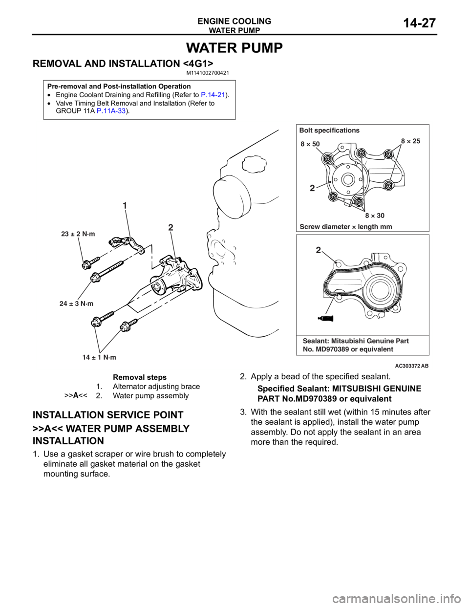
REMOVAL AND INSTALLATION <4G1>M1141002700421
Pre-removal and Post-installation Operation
•Engine Coolant Draining and Refilling (Refer to P.14-21).
•Valve Timing Belt Removal and Installation (Refer to
GROUP 11A P.11A-33).
AC303372
24 ± 3 N·m23 ± 2 N·m
14 ± 1 N·m
1 2
Bolt specifications
Screw diameter × length mm 8 × 50
8 × 308 × 25
AB
2
2
Sealant: Mitsubishi Genuine Part
No. MD970389 or equivalent
Removal steps
1.Alternator adjusting brace
>>A<<2.Water pump assembly
INST ALLA T ION SER VICE POINT
>>A<< WA TER PUMP ASSEMBL Y
INST
ALLA TION
1.Use a gaske t scraper o r wire brush to complet e ly
eliminate all gasket material o n the g a sket
mounting surface.
2. App l y a bead of the specified sealan t.
Specified Sealant: MITSUBISHI GENUINE
P
ART No.MD970 389 or eq uivalen t
3.With the sea l ant still wet (within 1 5 minutes af ter
th e se alant is applied), inst all the wa ter pump
a sse mbly . Do not a pply the sealant in an are a
more th an the required.
Page 42 of 800

WATE R P U M P
ENGINE COOLING14-28
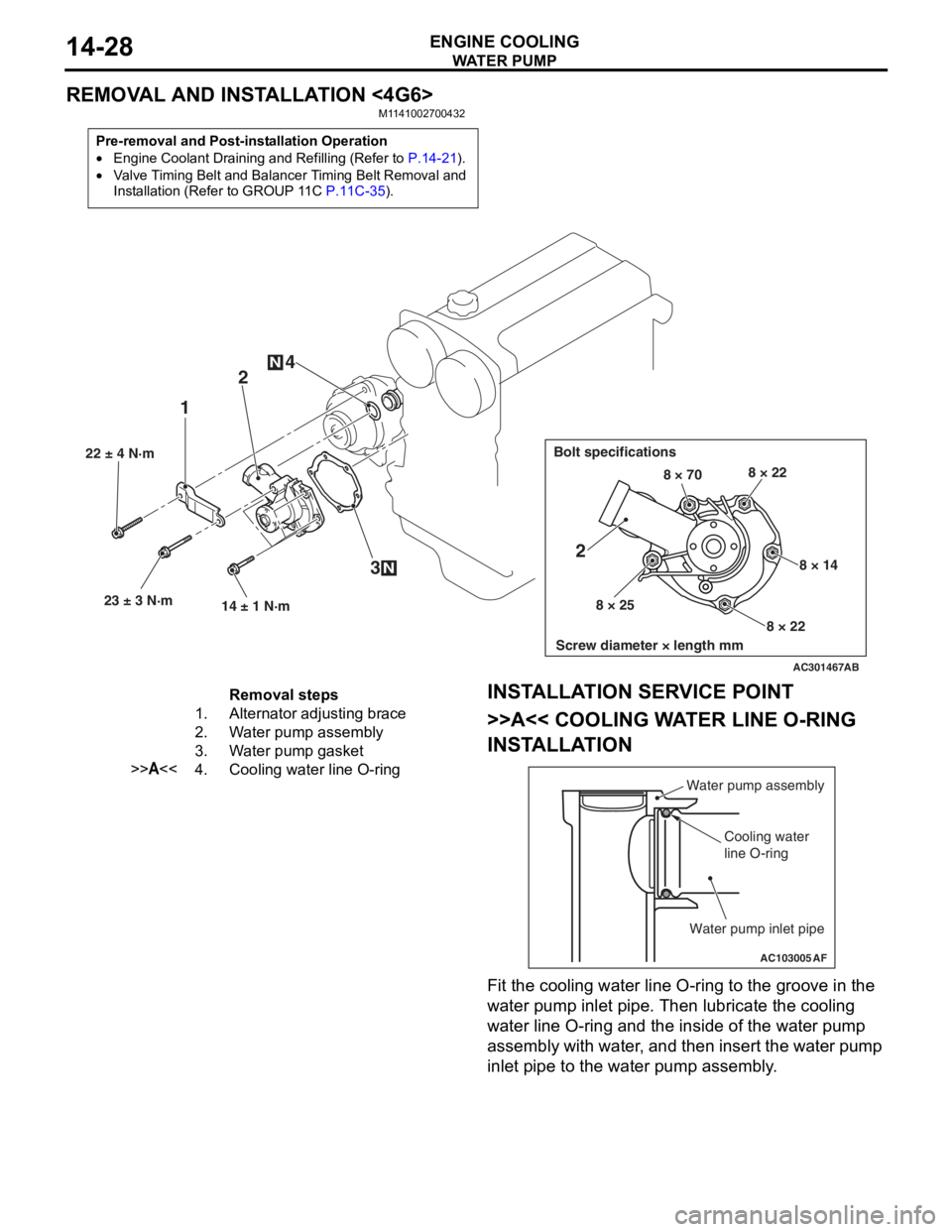
REMOVAL AND INSTALLATION <4G6>
M1141002700432
Pre-removal and Post-installation Operation
•Engine Coolant Draining and Refilling (Refer to P.14-21).
•Valve Timing Belt and Balancer Timing Belt Removal and
Installation (Refer to GROUP 11C
P.11C-35).
AC301467
22 ± 4 N·m23 ± 3 N·m 14 ± 1 N·m
12
3
4
N
N
Bolt specifications
Screw diameter × length mm
8 × 70 8 × 22
8 × 14
8 × 22
8 × 25
2
AB
Removal steps
1.Alternator adjusting brace
2.Water pump assembly
3.Water pump gasket
>>A<<4.Cooling water line O-ring
INST
ALLA T ION SER VICE POINT
>>A<< COOLING WA TER LINE O-RING
INST
ALLA TION
AC103005
Water pump assembly
Cooling water
line O-ring
Water pump inlet pipe
AF
Fit the coo ling water line O-ring to the groove in the
wa
ter pump in let p i pe. T hen lubricate th e co olin g
wa
ter line O-ring and the inside of the wat e r pump
assembly with wa
ter , and then insert the wa ter pu mp
inle
t pip e to the water pu mp asse mbly .
Page 146 of 800

DRIVESHAFT ASSEMBLY
FRONT AXLE26-14
DRIVESHAFT ASSEMBLY
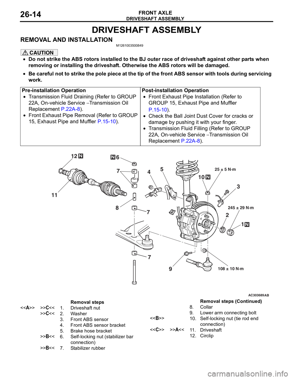
REMOVAL AND INSTALLATIONM1261003500849
CAUTION
•Do not strike the ABS rotors installed to the BJ outer race of driveshaft against other parts when
removing or installing the driveshaft. Otherwise the ABS rotors will be damaged.
•
Pre-installation Operation
•Transmission Fluid Draining (Refer to GROUP
22A, On-vehicle Service
− Transmission Oil
Replacement
P.22A-8).
•Front Exhaust Pipe Removal (Refer to GROUP
15, Exhaust Pipe and Muffler
P.15-10).
Post-installation Operation
•Front Exhaust Pipe Installation (Refer to
GROUP 15, Exhaust Pipe and Muffler
P.15-10).
•Check the Ball Joint Dust Cover for cracks or
damage by pushing it with your finger.
•Transmission Fluid Filling (Refer to GROUP
22A, On-vehicle Service
− Transmission Oil
Replacement
P.22A-8).
AC303689AB
9
N
N
NN
10
7
4
3
2 1
25 ± 5 N·m
245 ± 29 N·m
108 ± 10 N·m
8
5
6
11 12
77
Removal steps
<>>>C<<1.Driveshaft nut
>>C<<2.Washer
3.Front ABS sensor
4.Front ABS sensor bracket
5.Brake hose bracket
>>B<<6.Self-locking nut (stabilizer bar
connection)
>>B<<7.Stabilizer rubber
8.Collar
9.Lower arm connecting bolt
<>10.Self-locking nut (tie rod end
connection)
<
12.Circlip
Be careful not to strike the pole piece at the tip of the front ABS sensor with tools during servicing
work.
Removal steps (Continued)
Page 253 of 800

POWER STEERING GEAR BOX AND LINKAGE
POWER STEERING37-23
POWER STEERING GEAR BOX AND LINKAGE
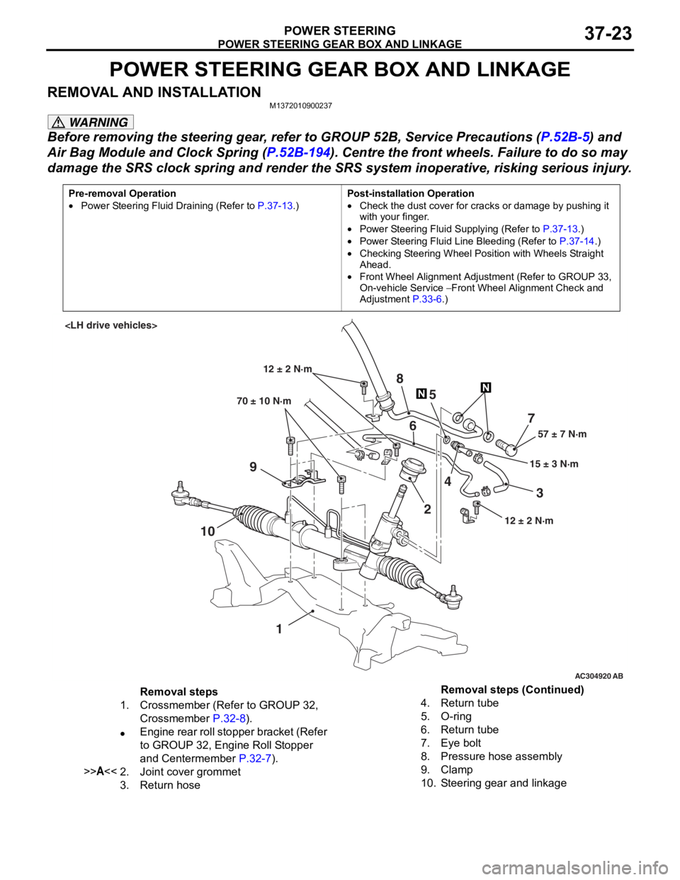
REMOVAL AND INSTALLATIONM1372010900237
WARNING
Before removing the steering gear, refer to GROUP 52B, Service Precautions (P.52B-5) and
Air Bag Module and Clock Spring (P.52B-194). Centre the front wheels. Failure to do so may
damage the SRS clock spring and render the SRS system inoperative, risking serious injury.
Pre-removal Operation
•Power Steering Fluid Draining (Refer to P.37-13.)
Post-installation Operation
•Check the dust cover for cracks or damage by pushing it
with your finger.
•Power Steering Fluid Supplying (Refer to P.37-13.)
•Power Steering Fluid Line Bleeding (Refer to P.37-14.)
•Checking Steering Wheel Position with Wheels Straight
Ahead.
•Front Wheel Alignment Adjustment (Refer to GROUP 33,
On-vehicle Service
− Front Wheel Alignment Check and
Adjustment
P.33-6.)
AC304920 AB
57 ± 7 N·m
15 ± 3 N·m
70 ± 10 N·m
7
3
8
5
6
9
10 24
1
12 ± 2 N·m
12 ± 2 N·m
Removal steps
1.Crossmember (Refer to GROUP 32,
Crossmember
P.32-8).
•Engine rear roll stopper bracket (Refer
to GROUP 32, Engine Roll Stopper
and Centermember
P.32-7).
>>A<<2.Joint cover grommet
3.Return hose
4.Return tube
5.O-ring
6.Return tube
7.Eye bolt
8.Pressure hose assembly
9.Clamp
10.Steering gear and linkage
Removal steps (Continued)