headlamp MITSUBISHI LANCER 2006 Workshop Manual
[x] Cancel search | Manufacturer: MITSUBISHI, Model Year: 2006, Model line: LANCER, Model: MITSUBISHI LANCER 2006Pages: 800, PDF Size: 45.03 MB
Page 66 of 800
CHARGING SYSTEM
ENGINE ELECTRICAL16-4
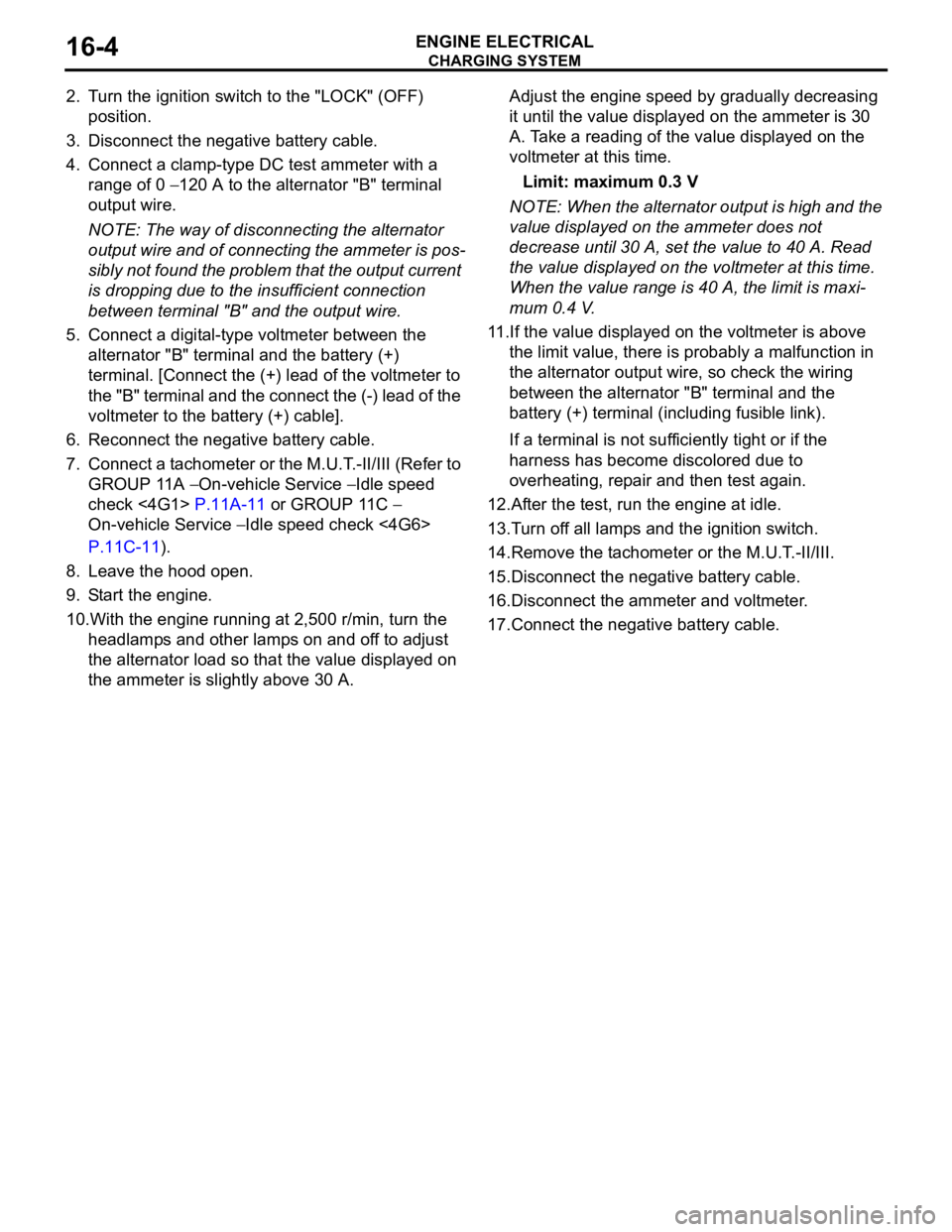
2. Turn the ignition switch to the "LOCK" (OFF)
position.
3. Disconnect the negative battery cable.
4. Connect a clamp-type DC test ammeter with a
range of 0
− 120 A to the alternator "B" terminal
output wire.
NOTE: The way of disconnecting the alternator
output wire and of connecting the ammeter is pos
-
sibly not found the problem that the output current
is dropping due to the insufficient connection
between terminal "B" and the output wire.
5. Connect a digital-type voltmeter between the
alternator "B" terminal and the battery (+)
terminal. [Connect the (+) lead of the voltmeter to
the "B" terminal and the connect the (-) lead of the
voltmeter to the battery (+) cable].
6. Reconnect the negative battery cable.
7. Connect a tachometer or the M.U.T.-II/III (Refer to
GROUP 11A
− On-vehicle Service − Idle speed
check <4G1>
P.11A-11 or GROUP 11C −
On-vehicle Service − Idle speed check <4G6>
P.11C-11).
8. Leave the hood open.
9. Start the engine.
10.With the engine running at 2,500 r/min, turn the
headlamps and other lamps on and off to adjust
the alternator load so that the value displayed on
the ammeter is slightly above 30 A.
Adjust the engine speed by gradually decreasing
it until the value displayed on the ammeter is 30
A. Take a reading of the value displayed on the
voltmeter at this time.
Limit: maximum 0.3 V
NOTE: When the alternator output is high and the
value displayed on the ammeter does not
decrease until 30 A, set the value to 40 A. Read
the value displayed on the voltmeter at this time.
When the value range is 40 A, the limit is maxi
-
mum 0.4 V.
11.If the value displayed on the voltmeter is above
the limit value, there is probably a malfunction in
the alternator output wire, so check the wiring
between the alternator "B" terminal and the
battery (+) terminal (including fusible link).
If a terminal is not sufficiently tight or if the
harness has become discolored due to
overheating, repair and then test again.
12.After the test, run the engine at idle.
13.Turn off all lamps and the ignition switch.
14.Remove the tachometer or the M.U.T.-II/III.
15.Disconnect the negative battery cable.
16.Disconnect the ammeter and voltmeter.
17.Connect the negative battery cable.
Page 68 of 800

CHARGING SYSTEM
ENGINE ELECTRICAL16-6
9. Check that the reading on the voltmeter is equal
to the battery voltage.
NOTE: If the voltage is 0 V, the cause is probably
an open circuit in the wire or fusible link between
the alternator "B" terminal and the battery (+) ter
-
minal.
10.Turn the light switch on to turn on headlamps and
then start the engine.
11.Immediately after setting the headlamps to high
beam and turning the heater blower switch to the
high revolution position, increase the engine
speed to 2,500 r/min and read the maximum
current output value displayed on the ammeter.
Limit: 70 % of normal current output
NOTE: .
•For the nominal current output, refer to the
Alternator Specifications.
•Because the current from the battery will soon
drop after the engine is started, the above step
should be carried out as quickly as possible in
order to obtain the maximum current output
value.
•The current output value will depend on the
electrical load and the temperature of the
alternator body.
•If the electrical load is small while testing, the
specified level of current may not be output
even though the alternator is normal. In such
cases, increase the electrical load by leaving
the headlamps turned on for some time to dis
-
charge the battery or by using the lighting sys-
tem in another vehicle, and then test again.
•The specified level of current also may not be
output if the temperature of the alternator body
or the ambient temperature is too high. In such
cases, cool the alternator and then test again.
12.The reading on the ammeter should be above the
limit value. If the reading is below the limit value
and the alternator output wire is normal, remove
the alternator from the engine and check the
alternator.
13.Run the engine at idle after the test.
14.Turn the ignition switch to the "LOCK" (OFF)
position.
15.Remove the tachometer or the M.U.T.-II/III.
16.Disconnect the negative battery cable.
17.Disconnect the ammeter and voltmeter.
18.Connect the negative battery cable.
Page 72 of 800
CHARGING SYSTEM
ENGINE ELECTRICAL16-10
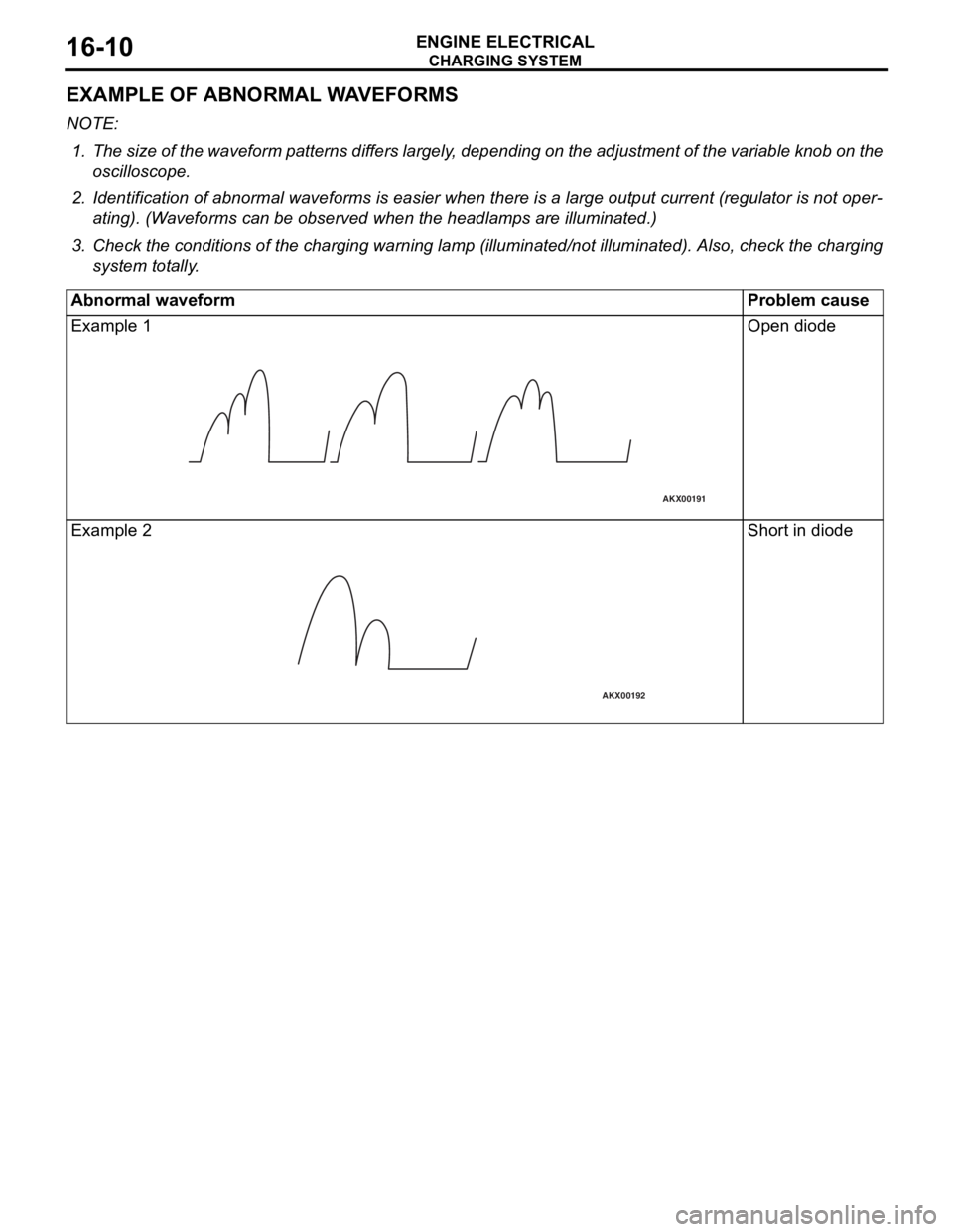
EXAMPLE OF ABNORMAL WAVEFORMS
NOTE: .
1. The size of the waveform patterns differs largely, depending on the adjustment of the variable knob on the
oscilloscope.
2. Identification of abnormal waveforms is easier when th ere is a large output current (regulator is not oper-
ating). (Waveforms can be observed when the headlamps are illuminated.)
3. Check the conditions of the charging warning lamp (illuminated/not illum inated). Also, check the charging
system totally.
Abnormal waveformProblem cause
Example 1
AKX00191
Open diod e
Exampl e 2
AKX00192
Shor t in diode
Page 334 of 800
51-2
HEADLAMP WASHER
TROUBLESHOOTING . . . . . . . . . . . . . . . . 51-39
HEADLAMP WASHER . . . . . . . . . . . . . . . . 51-39
REMOVAL AND INSTALLATION . . . . . . . . 51-39
INSPECTION . . . . . . . . . . . . . . . . . . . . . . . 51-40
MARK . . . . . . . . . . . . . . . . . . . . . . . . .51-41
REMOVAL AND INSTALLATION . . . . . . . . 51-41
DOOR MIRROR . . . . . . . . . . . . . . . . .51-43
GENERAL INFORMATION . . . . . . . . . . . . . 51-43
SERVICE SPECIFICATION . . . . . . . . . . . . 51-43
SPECIAL TOOL. . . . . . . . . . . . . . . . . . . . . . 51-43
TROUBLESHOOTING . . . . . . . . . . . . . . . . 51-43
DIAGNOSIS TROUBLESHOOTING FLOW 51-43
TROUBLE SYMPTOM CHART . . . . . . . . . . 51-43
SYMPTOM PROCEDURES . . . . . . . . . . . . 51-44
DOOR MIRROR . . . . . . . . . . . . . . . . . . . . . 51-50
REMOVAL AND INSTALLATION . . . . . . . . 51-50
INSPECTION. . . . . . . . . . . . . . . . . . . . . . . . 51-51
Page 371 of 800
HEADLAMP WASHER
EXTERIOR51-39
HEADLAMP WASHER
TROUBLESHOOTINGM1511000700356
The headlamp washer is controlled by the Smart Wir-
ing System (SWS). For troubleshooting, refer to
GROUP 54B, Troubleshooting
P.54B-15 or GROUP
54C, Troubleshooting P.54C-4.
HEADLAMP WASHER
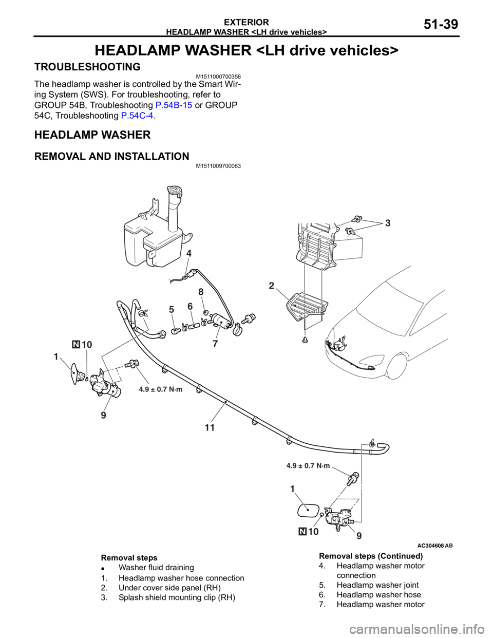
REMOVAL AND INSTALLATION
M1511009700063
AC304608AB
10N
2
4
56
8
7
1
9
11
9
1
10N
4.9 ± 0.7 N·m
4.9 ± 0.7 N·m
3
Removal steps
•Washer fluid draining
1.Headlamp washer hose connection
2.Under cover side panel (RH)
3.Splash shield mounting clip (RH)
4.Headlamp washer motor
connection
5.Headlamp washer joint
6.Headlamp washer hose
7.Headlamp washer motor
Removal steps (Continued)
Page 372 of 800
HEADLAMP WASHER
EXTERIOR51-40
INSPECTION
M1511009800082
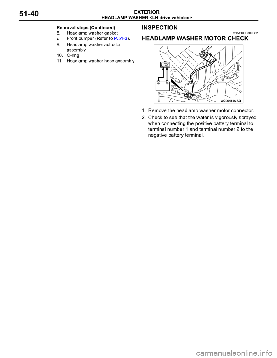
HEADLAMP WASHER MOTOR CHECK
AC304136AB
12
1.Remove the he adla m p washer motor connector .
2.Check to se e tha t the wat e r is vigorou sly sp rayed
when con nect i ng th e positive ba ttery terminal to
te rmin al nu mber 1 and terminal n u mb er 2 to the
n egative ba ttery terminal.
8.Headlamp wa s h er gasket
•Fr o n t b u m p er ( R ef er to P.51-3).
9.Head lam p wa sh er a c tu ator
assembly
10.O-rin g
11.Headlamp w a s h er hose assembly
Remo val st ep s ( C o n tinue d)
Page 416 of 800
ENGINE COMPARTMENT
CONFIGURATION DIAGRAMS80-6
ENGINE COMPARTMENT
ENGINE COMPARTMENT
AC301123
Front wiring
harness (RH)
A-01
A-32
A-31
A-29
A-28
A-27
A-26
A-25 A-23
A-24 A-22
AC
1
Front bumper
wiring harness
Connector colour
code
B : Black
BR : Brown
G : Green
GR : Grey
L : Blue
None : Milk white
O : Orange
R : Red
V : Violet
Y : Yellow
Connector
symbol
A
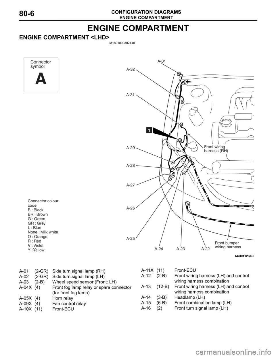
A-01(2-GR)Side turn signal lamp (RH)
A-02(2-GR)Side turn signal lamp (LH)
A-03(2-B)Wheel speed sensor (Front: LH)
A-04X(4)Front fog lamp relay or spare connector
(for front fog lamp)
A-05X(4)Horn relay
A-09X(4)Fan control relay
A-10X(11)Front-ECU
A-11X(11)Front-ECU
A-12(2-B)Front wiring harness (LH) and control
wiring harness combination
A-13(12-B)Front wiring harness (LH) and control
wiring harness combination
A-14(3-B)Headlamp (LH)
A-15(6-B)Front combination lamp (LH)
A-16(2)Front turn signal lamp (LH)
Page 417 of 800
AC502048AB
A-02A-03
A-04X
A-05X
A-09X
A-10X
A-11X
A-12
A-13
A-14
A-15
A-16
A-17
A-18
A-19
A-20
A-21 Front wiring
harness
(LH)
12
A-33
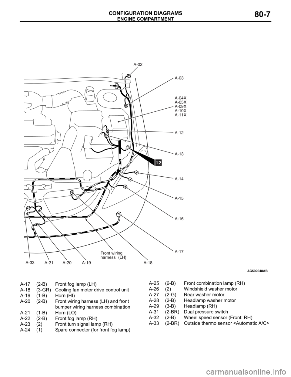
A-17(2-B)Front fog lamp (LH)
A-18(3-GR)Cooling fan motor drive control unit
A-19(1-B)Horn (HI)
A-20(2-B)Front wiring harness (LH) and front
bumper wiring harness combination
A-21(1-B)Horn (LO)
A-22(2-B)Front fog lamp (RH)
A-23(2)Front turn signal lamp (RH)
A-24(1)Spare connector (for front fog lamp)
A-25(6-B)Front combination lamp (RH)
A-26(2)Windshield washer motor
A-27(2-G)Rear washer motor
A-28(2-B)Headlamp washer motor
A-29(3-B)Headlamp (RH)
A-31(2-BR)Dual pressure switch
A-32(2-B)Wheel speed sensor (Front: RH)
A-33(2-BR)Outside thermo sensor
ENGINE COMP AR TMEN T
CONF IGURA TION D I A G RA MS80-7
Page 418 of 800
ENGINE COMPARTMENT
CONFIGURATION DIAGRAMS80-8
ENGINE COMPARTMENT
M1801000302451
AC301126
Front wiring
harness (RH)
A-01
A-32
A-31
A-29 A-30
A-27
A-26
A-25 A-23
A-24 A-22
AC
1
Front bumper
wiring harness
Connector colour
code
B : Black
BR : Brown
G : Green
GR : Grey
L : Blue
None : Milk white
O : Orange
R : Red
V : Violet
Y : Yellow
Connector
symbol
A
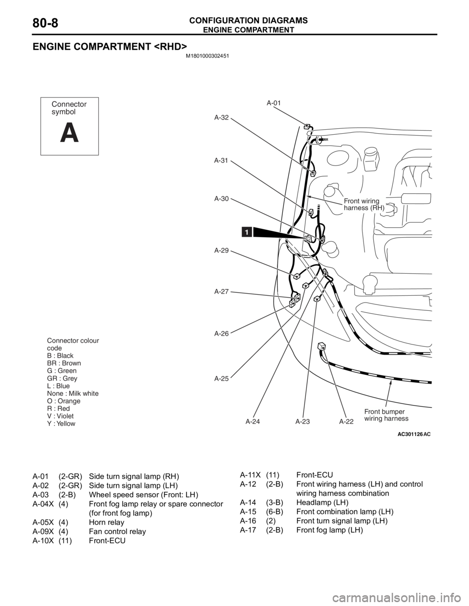
A-01(2-GR)Side turn signal lamp (RH)
A-02(2-GR)Side turn signal lamp (LH)
A-03(2-B)Wheel speed sensor (Front: LH)
A-04X(4)Front fog lamp relay or spare connector
(for front fog lamp)
A-05X(4)Horn relay
A-09X(4)Fan control relay
A-10X(11)Front-ECU
A-11X(11)Front-ECU
A-12(2-B)Front wiring harness (LH) and control
wiring harness combination
A-14(3-B)Headlamp (LH)
A-15(6-B)Front combination lamp (LH)
A-16(2)Front turn signal lamp (LH)
A-17(2-B)Front fog lamp (LH)
Page 419 of 800
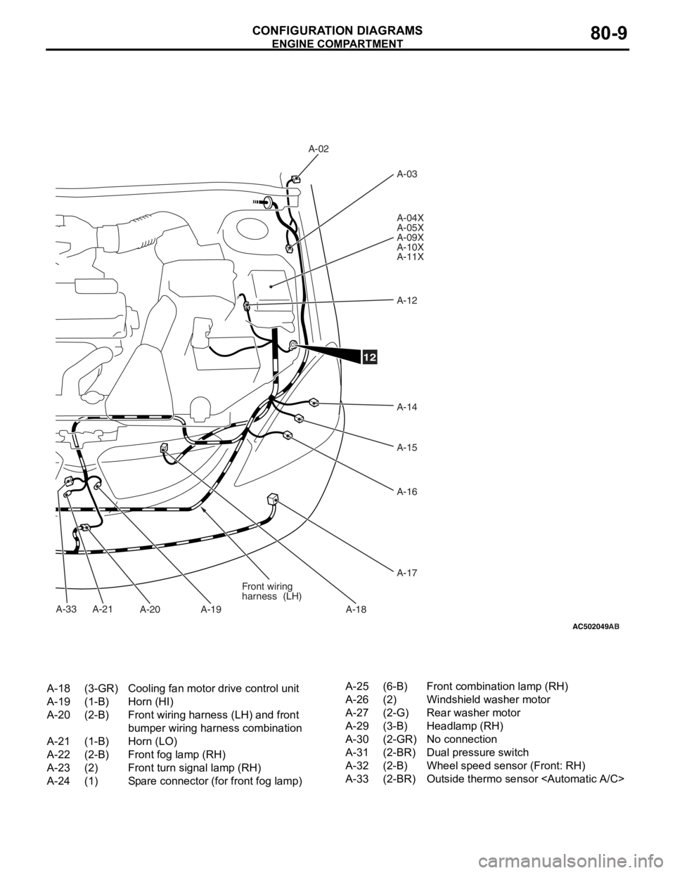
AC502049
A-33
AB
A-02A-03
A-04X
A-05X
A-09X
A-10X
A-11X
A-12
A-14
A-15
A-16
A-17
A-18
A-19
A-20
A-21 Front wiring
harness
(LH)
12
A-18(3-GR)Cooling fan motor drive control unit
A-19(1-B)Horn (HI)
A-20(2-B)Front wiring harness (LH) and front
bumper wiring harness combination
A-21(1-B)Horn (LO)
A-22(2-B)Front fog lamp (RH)
A-23(2)Front turn signal lamp (RH)
A-24(1)Spare connector (for front fog lamp)
A-25(6-B)Front combination lamp (RH)
A-26(2)Windshield washer motor
A-27(2-G)Rear washer motor
A-29(3-B)Headlamp (RH)
A-30(2-GR)No connection
A-31(2-BR)Dual pressure switch
A-32(2-B)Wheel speed sensor (Front: RH)
A-33(2-BR)Outside thermo sensor
ENGINE COMP AR TMEN T
CONF IGURA TION D I A G RA MS80-9