load capacity MITSUBISHI LANCER 2006 Workshop Manual
[x] Cancel search | Manufacturer: MITSUBISHI, Model Year: 2006, Model line: LANCER, Model: MITSUBISHI LANCER 2006Pages: 800, PDF Size: 45.03 MB
Page 482 of 800

CENTRALIZED JUNCTION
CIRCUIT DIAGRAMS90-18
CENTRALIZED JUNCTION
M1901000301477
FUSIBLE LINK AND FUSE
ENGINE COMPARTMENT
No.Power supply circuitNameRated
capacity (A)Housing
colourLoad circuit
1Battery/ Alternator
(Fusible link No.26)Fusible
link60YellowFuse No.15, 16, 18, 19, 20 (in junction
block) circuit
250RedFan controller
360YellowABS-ECU
440GreenIgnition switch circuit
530PinkPower window main switch and power
window sub switch
6Fuse15BlueFront fog lamp, front fog lamp
indicator lamp, front fog lamp relay
and spare connector (for front fog
lamp)
710RedHorn relay and horn
820YellowAir cleaner air flow sensor, camshaft
position sensor, emission solenoid
valve (EGR system), emission
solenoid valve (purge control system),
engine-A/T-ECU, engine-ECU, engine
control oxygen sensor, engine control
relay, engine crank angle sensor, fan
control relay, fuel injector, ignition coil
relay, immobilizer-ECU and throttle
body idle speed control servo
910RedA/C compressor
1015BlueABS-ECU, engine-A/T-ECU, high
mount stop lamp and rear combination
lamp
1115BlueAccessory socket
127.5BrownAlternator
1310RedETACS-ECU, front turn signal lamp,
rear combination lamp, side turn
signal lamp and turn signal indicator
lamp
1420YellowA/T control solenoid valve assembly
and engine-A/T-ECU
1515BlueFuel pump
16Front-ECU
(Headlamp relay: HI)10RedHeadlamp (RH)
1710RedHeadlamp (LH) and high beam
indicator lamp
18Front-ECU
(Headlamp relay: LO)10RedHeadlamp (RH)
1910RedHeadlamp (LH), headlamp assembly
and headlamp levelling switch
Page 483 of 800

CENTRALIZED JUNCTION
CIRCUIT DIAGRAMS90-19
20Front-ECU (Tail lamp
relay)Fuse7.5BrownA/C-ECU, ashtray illumination lamp,
cigarette lighter illumination lamp,
combination meter, fog lamp switch,
front turn signal lamp, hazard warning
switch, headlamp assembly (RH),
headlamp levelling switch, heated
seat switch, heater control unit,
licence plate lamp, rear combination
lamp, rheostat, side turn signal lamp
and spare connector (for audio)
217.5BrownCombination meter, headlamp
assembly (LH), licence plate lamp,
position lamp (LH) and rear
combination lamp (LH)
22Battery/ Alternator
(Fusible link No.26)10RedCombination meter, column switch,
ETACS-ECU and front-ECU
23Ignition switch (ACC)10RedClock, ETACS-ECU and spare
connector (for audio)
24−−−−
25Battery/ Alternator
(Fusible link No.26)20YellowHeated seat assembly and heated
seat switch
26AlternatorFusible
link100 <4G1>
120 <4G6>−Battery, fusible link No.1, 2, 3, 4, 5,
fuse No.6, 7, 8, 9, 10, 11, 12, 13, 14,
15, 22 (relay box) and front-ECU
No. Power supply circuit Name Rated
capacity (A)Housing
colourLoad circuit
AC208462
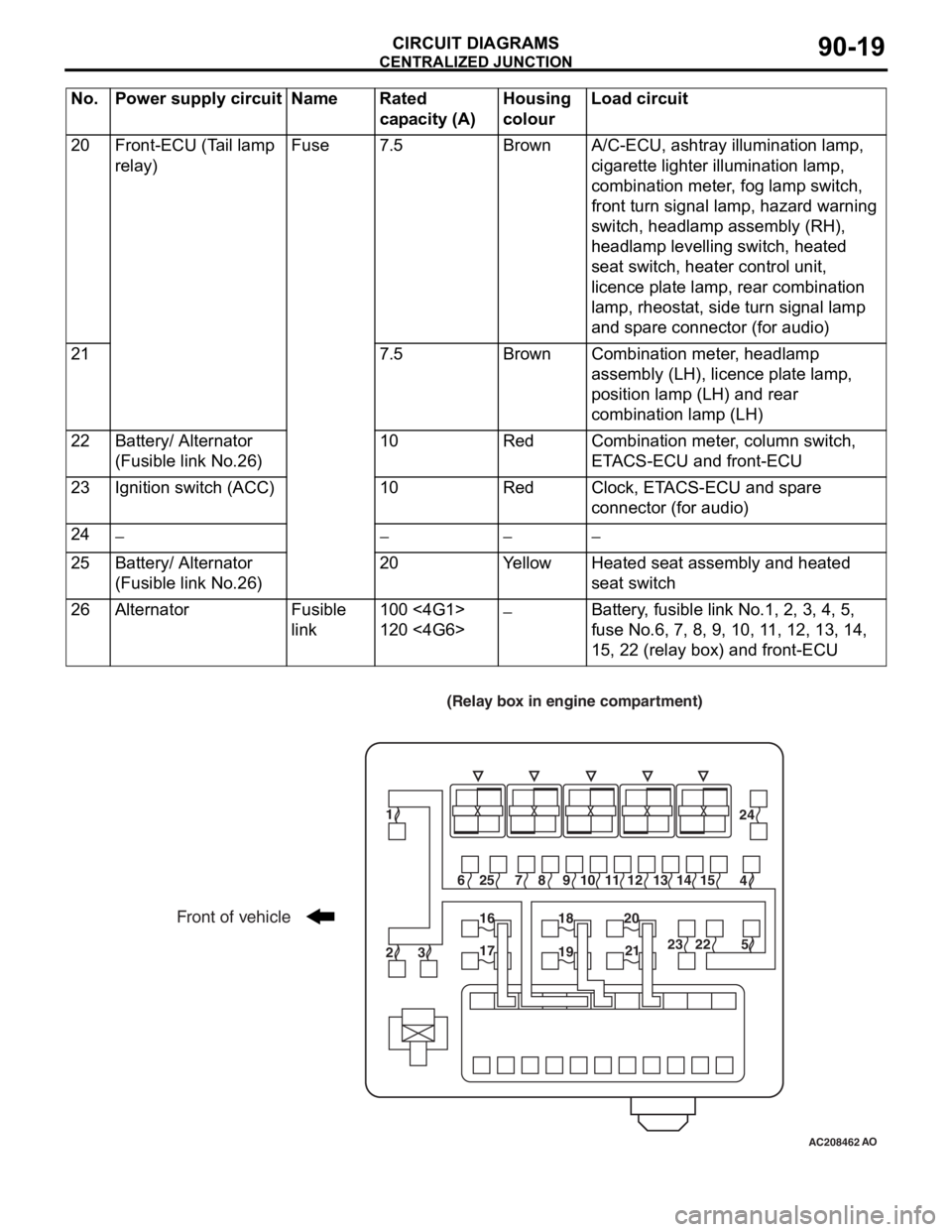
Front of vehicle
(Relay box in engine compartment)
1
6
7 8 9 10 1112 13141524
4 25
2316
1718
1920
2123 225
AO
Page 484 of 800

CENTRALIZED JUNCTION
CIRCUIT DIAGRAMS90-20
PASSENGER COMPARTMENT
AC207745
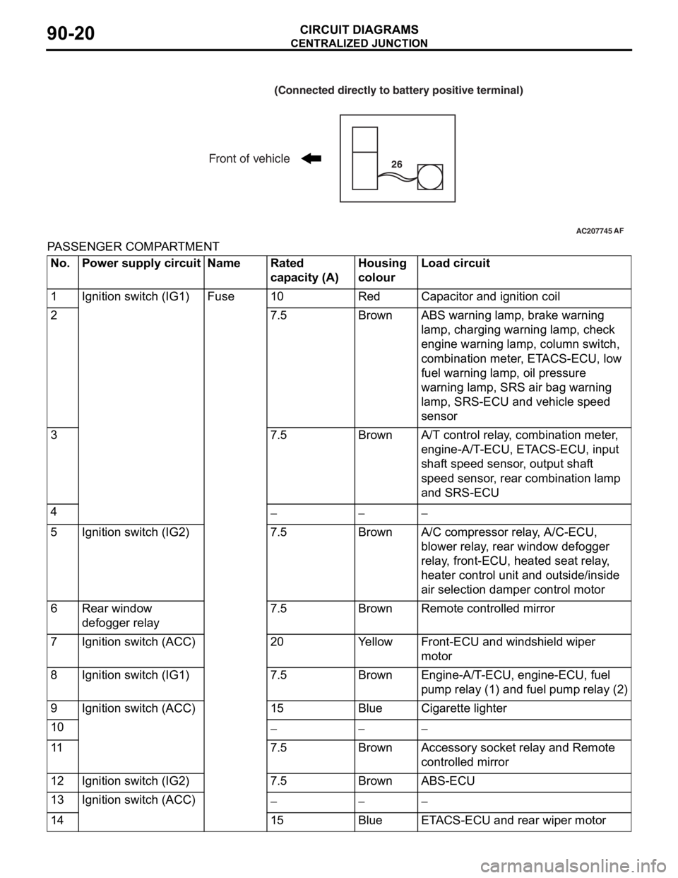
(Connected directly to battery positive terminal)
Front of vehicle26
AF
No.Power supply circuitNameRated
capacity (A)Housing
colourLoad circuit
1Ignition switch (IG1)Fuse10RedCapacitor and ignition coil
27.5BrownABS warning lamp, brake warning
lamp, charging warning lamp, check
engine warning lamp, column switch,
combination meter, ETACS-ECU, low
fuel warning lamp, oil pressure
warning lamp, SRS air bag warning
lamp, SRS-ECU and vehicle speed
sensor
37.5BrownA/T control relay, combination meter,
engine-A/T-ECU, ETACS-ECU, input
shaft speed sensor, output shaft
speed sensor, rear combination lamp
and SRS-ECU
4−−−
5Ignition switch (IG2)7.5BrownA/C compressor relay, A/C-ECU,
blower relay, rear window defogger
relay, front-ECU, heated seat relay,
heater control unit and outside/inside
air selection damper control motor
6Rear window
defogger relay7.5BrownRemote controlled mirror
7Ignition switch (ACC)20YellowFront-ECU and windshield wiper
motor
8Ignition switch (IG1)7.5BrownEngine-A/T-ECU, engine-ECU, fuel
pump relay (1) and fuel pump relay (2)
9Ignition switch (ACC)15BlueCigarette lighter
10−−−
117.5BrownAccessory socket relay and Remote
controlled mirror
12Ignition switch (IG2)7.5BrownABS-ECU
13Ignition switch (ACC)−−−
1415BlueETACS-ECU and rear wiper motor
Page 485 of 800

CENTRALIZED JUNCTION
CIRCUIT DIAGRAMS90-21
15Fusible link No.1Fuse15BlueDiagnosis connector
1610RedRear fog lamp, rear fog lamp indicator
lamp and rear fog lamp relay
17−−−
18−−−
1930GreenA/C-ECU, blower motor, heater control
unit and resistor
2030GreenRear window defogger
No. Power supply circuit Name Rated
capacity (A)Housing
colourLoad circuit
AC209082
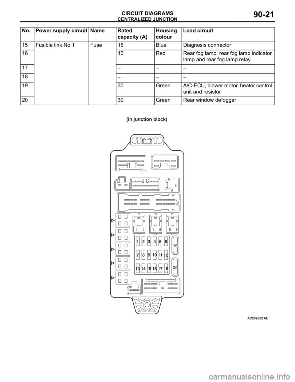
(in junction block)
1234
56
7
89
20 19
10 11
12
131415
16
1718
AE