ESP MITSUBISHI LANCER 2014 8.G Owner's Manual
[x] Cancel search | Manufacturer: MITSUBISHI, Model Year: 2014, Model line: LANCER, Model: MITSUBISHI LANCER 2014 8.GPages: 434, PDF Size: 57.5 MB
Page 137 of 434
Continuously variable transm
ission (CVT) (if so equipped)
5-70 Features and controls
5
N00514500287
N00514900063
To gain extra acceleration in “D” (DRIVE) position (when passing another vehicle) push the accelerator to the floor if it is safe to do so in traffic conditions. The CVT will automati-cally downshift.
N00515000074
For short waiting periods, such as at traffic lights, the vehicle can be left in selector lever position and held stationary with the servicebrake.
For longer waiting periods with the engine running, the selector lever should be placed in the “N” (NEUTRAL) position.
N00515100062
To park the vehicle, first bring it to a com- plete stop, fully engage the parking brake,and then move the selector lever to the “P” (PARK) position. If you are going to l
eave the vehicle unat-
tended, always switch off the engine and carry the key.
Operation of the CVT
CAUTION Before selecting a position with the engine running and the vehicle stationary, fully depress the brake pedal to prevent the vehi- cle from creeping.Do not release the brakes until you are ready to drive away. The vehicle will begin to move as soon as the CVT is engaged, espe-cially when the engine speed is high (fast idle or air conditioning on). Depress the brake pedal with the right foot. Using the left foot could cause driver move- ment delay in case of an emergency. To prevent sudden acceleration, never run the engine at high rpms when shifting fromthe “P” (PARK) or “N” (NEUTRAL) posi- tion. Operating the accelerator pedal while the other foot is resting on the brake pedal will affect braking efficiency and may cause pre-mature wear of brake pads. Use the selector lever in the correct shift position in accordance with driving condi- tions. Never coast downhill backward in the driv- ing shift position { “D” (DRIVE), “L” (LOW) or sports mode} or coast forward inthe “R” (REVERSE) position. Engine stopping and increased brake pedal and steering effort could lead to an accident.
Do not rev the engine with the brake pedal pressed when the vehicle is stationary. This can damage the CVT. Also, when you depress the accelerator pedal while holding down the brake pedal with theselector lever in the “D” (DRIVE) position, the engine revolutions may not rise as high as when performing the same operation withthe selector lever in the “N” (NEUTRAL) position.
Passing acceleration
NOTE
In sports mode, downshifts do not take place when the accelerator is depressed all the way to the floor.
Wa i t i n g
CAUTION
CAUTION To avoid transmission overheating, never try to keep your vehicle stationary on a hill by using the accelerator pedal. Always apply the parking brake and/or service brake. Unexpected acceleration may occur if the selector lever is in a position other than “P”(PARK) or “N” (NEUTRAL). Before driving off from a stop, make sure that the selector lever is in “D” (DRIVE)position or “Sports mode” position.
Parking
Page 138 of 434
Twin Clutch SST (Sportronic Shif
t Transmission) (if so equipped) Features and controls 5-71
5
N00515300194
If the CVT does not shift while driving, or your vehicle does not pick up enough speed when starting on an uphill slope, there may be something unusual happening in the transmis-sion, causing a safety device to activate. Have your vehicle checked at an authorized Mit- subishi Motors dealer or a repair facility ofyour choice as soon as possible. 1. If your vehicle has difficulty moving uphill, shift the selector lever into “L” (LOW) position (except for vehicles withsport mode) or 2nd shift range of the sports mode. This method might not work dependingon the type of transmission malfunction.
2. Once the vehicle is moving on a level road, move the selector lever back to “D” (DRIVE) position.
N00539700059
The Twin Clutch SST is a transmission that,through integrated control of the engine and transmission, is able to achieve both thesmooth shifting of an automatic transaxle and the acceleration and fuel economy close to a manual transaxle. In addition, the controlmode can be selected from two types to suit the driving conditions. Together with manual shifting, the transmis-sion is capable of responding to a variety of driving circumstances. Twin Clutch SST control mode
P.5-76
Manual shift
P.5-77
N00539800050
As an additional safe
ty precaution, models
equipped with a Twin Clutch SST have ashift-lock device that holds the gearshift lever in the “P” (PARK) position. To move the gearshift lever from the “P” (PARK) positionto another position, follow the steps below. 1. Press and hold the brake pedal down. 2. Move the gearshift lever to the desired position.
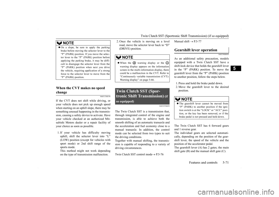
The Twin Clutch SST has 6 forward gears and 1 reverse gear. The individual gears are selected automati-cally, depending on the position of the gear- shift lever, the speed of the vehicle and the position of the accelerator pedal.The gearshift lever (A) has 2 gates; the main shift gate (B) and the manual shift gate (C).
NOTE
On a slope, be sure to apply the parking brake before moving the selector lever to the “P” (PARK) position. If you move the selec- tor lever to the “P” (PARK) position before applying the parking brake, it may be diffi-cult to disengage the selector lever from the “P” (PARK) position when next you drive the vehicle, requiring application of a strongforce to the selector le
ver to move from the
“P” (PARK) position.
When the CVT makes no speed change
NOTE
When the warning display or the warning display appears on the information screen in the multi-information display, therecould be a malfunction in the CVT. Refer to “Continuously variable transmission (CVT): Warning display” on page 5-66.
Twin Clutch SST (Spor- tronic Shift Transmission)
(if
so equipped)
Gearshift lever operation
NOTE
The gearshift lever cannot be moved from “P” (PARK) to another position if the igni-tion switch is at the “LOCK” or “ACC” posi- tion, or the key has been removed, or if the brake pedal is not pressed and held down.
Page 149 of 434
Twin Clutch SST (Sportronic Shif
t Transmission) (if so equipped)
5-82 Features and controls
5
lever position and held stationary with the service brake. For longer waiting periods with the engine running, place the gearshift lever in the “N”(NEUTRAL) position and apply the parking brake, while holding the vehicle stationary with the service brake.Prior to moving off after having stopped the vehicle, make sure that the gearshift lever is in “D” (DRIVE) position or manual shiftposition.
N00541100018
To park the vehicle, first bring it to a com- plete stop, fully engage the parking brake, and then move the gearshift lever to the “P”(PARK) position.
N00541201087
If there is a malfunction in the Twin Clutch SST or engine electronic control module, the following may occur. Twin Clutch SST does not shift. Vehicle cannot move. Twin Clutch SST acceleration is slow. Vehicle does not creep. “Shift shock” is large. Shifting occurs at higher engine speed. Response is slow.
If any of these occurs, perform the following procedure. The temperature of Twin
Clutch SST fluid is
high. Refer to “Warning display” on page 5-73 and follow the appropriate measures. There could be a malfunction in the engine electronic control module.
CAUTION Do not rev the engine unnecessarily while the vehicle is stationary. Unexpected acceler- ation may occur if the gearshift lever is in aposition other than “P” (PARK) or “N” (NEUTRAL). Do not keep the vehicle in a stopped position on an uphill slope by depressing the acceler- ator pedal instead of the brake pedal.The transmission may be damaged and an accident may occur due to the following con- ditions.• The Twin Clutch SST fluid temperaturewill rise and can cause transmission dam- age.
• If the vehicle is kept in a stopped positionby depressing the accelerator pedal instead of the brake pedal, the vehicle will vibrate or the warning display will appear on the information screen in the multi-infor- mation display to alert the driver that the Twin Clutch SST fluid temperature hasrisen. After that, if the Twin Clutch SST fluid temperature rises even higher, the transmis-sion protection control will operate. If this occurs, the vehicle may suddenly reverse as if the gearshift lever was in the “N” (NEUTRAL) position and cause an accident. If the warning display appears or the transmission protection control operates, refer to “When warning display is showing” on page 5-74.
Parking
CAUTION
What to do if the following occur with the Twin Clutch SST
When warning display is showing When the engine malfunction indicator (“SERVICE ENGINE SOON” or “Check engine light”) comes on or blinking
Page 150 of 434
ACD (Active center differential system) (if so equipped)
Features and controls 5-83
5
Refer to “Engine malfunction indicator (“SERVICE ENGINE SOON” or “Check engine light”)” on page 5-146 and follow the appropriate measures. A safety device in the Twin Clutch SST has been activated due to a possible malfunctionin the Twin Clutch SST. Refer to “If the gearshift lever position dis- play is not showing” on
page 5-73 and follow
the appropriate measures. A safety device in the Twin Clutch SST has been activated due to a possible malfunctionin the Twin Clutch SST or in the engine elec-tronic control module. Perform the following procedure.1. Park your vehicle in a safe place and stop the engine. 2. Restart the engine. If the vehicle moves and accelerates normally after this procedure is performed, there is no malfunction in the transmission.
However, if the vehicle does not move or accelerate normally, or if this problem occurs repeatedly, have the vehicle checked by an authorized Mitsubishi Motors dealer or arepair facility of your ch
oice as soon as possi-
ble.
N00538500034
The ACD is a system
that improves accelera-
tion performance and straight-ahead stabilityby regulating the differential limiting action and power drive distribution of the center dif- ferential.
N00545400048
Select the control mode from the followingthree types to suit the driving conditions.
When the gearshift lever position display is not showing When warning display is showing or when no warning is showing in the multi- information display
CAUTION When the Twin Clutch SST fluid tempera- ture is high, the engine idle speed when the vehicle is stopped may increase or the vehi- cle will have a weak tendency to creep. After that, if the Twin Clutch SST fluid tem- perature rises even higher, the warning display will appear.
ACD (Active center differ- ential system)
(if so equipped)
CAUTION Do not over-rely on th
e ACD. Even the ACD
cannot prevent the natural laws of physics from acting on the vehicle. This system, like any other system, has limits and cannot help you to maintain traction and control of thevehicle in all circumstances. Reckless driv- ing can lead to accidents. It is the driver’s responsibility to drive carefully. This meanstaking into account the traffic, road and envi- ronmental conditions. Be sure to use tires that are the same speci- fied size, type, and brand, and have no differ- ence in the amount of wear for all fourwheels. Otherwise, the ACD may not work properly.NOTE
If the parking brake lever is pulled up while the vehicle is moving, the center differential is designed to switch to a free state condition which will allow the rear wheel to lock eas-ier.
ACD control mode
Page 157 of 434
Limited-slip differential (if so equipped) 5-90 Features and controls
5
N00517400069
A limited-slip differential is applied for rear wheel differential. The features of this lim-ited-slip differential are described below: Just as with a conventional differential, the wheel on one side is a
llowed to turn at a dif-
ferent speed from the wheel on the other sidewhen the vehicle is cornering. The difference between the limited-slip differential and a conventional differential is that if the wheelon one side of the vehicle loses traction, a greater amount of torque is applied to the wheel on the other side to improve traction.
N00517500262
Overuse of the brake can cause poor brakeresponse and premature wear of the brakepads and linings. When driving down a long or steep hill, use engine braking by downshifting.
N00517600377
Your vehicle is equipped with power brakes for more braking force with minimal brake pedal effort.Your brakes are designed to operate at full capacity, even if the power assist is lost. If the power assist is lost, the effort needed topress the brake pedal is greater. If you should loose the power assist for some reason, the brakes will still work. If the power brake unit or either of the two brake hydraulic systems stops working prop-
Jacking up a all-wheel drive vehicles
WA R N I N G Do not start or run the engine while the vehicle is on the jack.The jack could slip out of position and result in an accident.
Limited-slip differential
(if so
equipped)
NOTE
Even if there is a difference in the amount of traction the wheels can get, if both of them are spinning, the limited-slip differential will not be effective.CAUTION Never start the engine while one of the front or rear wheels is jacked up and the other in contact with the ground; doing so may cause the vehicle to jump forward. Continuously attempting to extract the vehi- cle from snow, mud, etc. while using highengine rpm may damage the limited-slip dif- ferential. Using a compact spare wheel will adversely affect the limited-slip differential; replace the compact spare wheel with a standard sizewheel as soon as possible.
Service brake Brake pedal
WA R N I N G Do not leave any objects near the brake pedal or let a floor mat slide under it; doing so could prevent the full pedal stroke that would be necessary in an emergency. Make sure that the pedal canbe operated freely at all times. Make sure the floor mat is securely held in place.CAUTION It is important not to drive the vehicle with your foot resting on the brake pedal when braking is not required. This practice can result in very high brake temperatures, pre-mature pad and lining wear, and possible damage to the brakes.
Power brakes
Page 160 of 434
Anti-lock braking system
Features and controls 5-93
5
When using the anti-lock brakes (sudden braking), steering is slightly different from normal driving conditions. Use thesteering wheel carefully. Always keep a safe distance from the vehicle in front of you. Even if your vehi-cle is equipped with the anti-lock braking system, leave a greater braking distance when:• Driving on gravel or snow-coveredroads. • Driving on uneven road surfaces. Operation of anti-lock braking system is not restricted to situations where brakes are applied suddenly. This system may also prevent the wheels from lockingwhen you drive over manholes, steel roadwork plates, road markings, or any uneven road surface. When the anti-lock braking system is in use, you may feel the brake pedal vibrat- ing and hear a unique sound. You mayalso feel as if the pedal resists being pressed. In this situation, simply hold the brakepedal down firmly. Do not pump the brake, which will result in reduced braking performance.
N00531600573
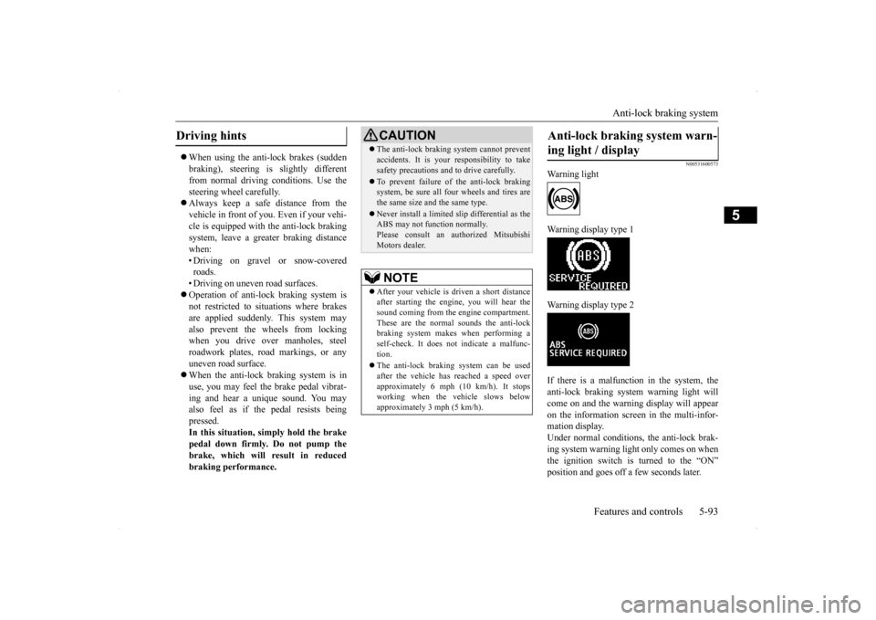
Warning light Warning display type 1 Warning display type 2 If there is a malfunction in the system, the anti-lock braking system warning light willcome on and the warning display will appearon the information screen in the multi-infor- mation display. Under normal conditions, the anti-lock brak-ing system warning light only comes on when the ignition switch is turned to the “ON” position and goes off a few seconds later.
Driving hints
CAUTION The anti-lock braking system cannot prevent accidents. It is your responsibility to take safety precautions and to drive carefully. To prevent failure of the anti-lock braking system, be sure all four wheels and tires are the same size and the same type. Never install a limited s
lip differential as the
ABS may not function normally. Please consult an authorized MitsubishiMotors dealer.NOTE
After your vehicle is driven a short distance after starting the engine, you will hear thesound coming from the engine compartment. These are the normal sounds the anti-lock braking system makes when performing aself-check. It does not indicate a malfunc- tion. The anti-lock braking system can be used after the vehicle has reached a speed over approximately 6 mph (10 km/h). It stopsworking when the vehicle slows below approximately 3 mph (5 km/h).
Anti-lock braking system warn- ing light / display
Page 162 of 434
Active Stability Control (ASC) (if so equipped)
Features and controls 5-95
5
N00529200022
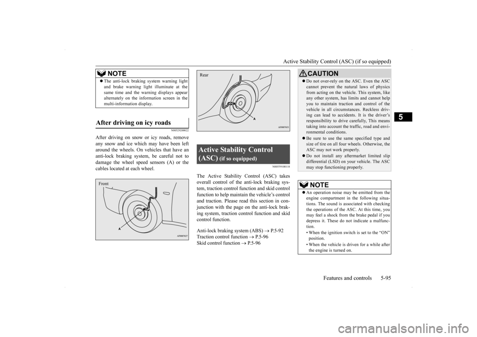
After driving on snow or icy roads, remove any snow and ice which may have been left around the wheels. On vehicles that have an anti-lock braking system, be careful not todamage the wheel speed sensors (A) or the cables located at each wheel.
N00559100118
The Active Stability Control (ASC) takesoverall control of the anti-lock braking sys- tem, traction control function and skid controlfunction to help maintain the vehicle’s controland traction. Please read
this section in con-
junction with the page on the anti-lock brak- ing system, traction control function and skidcontrol function. Anti-lock braking system (ABS)
P.5-92
Traction control function
P.5-96
Skid control function
P.5-96
NOTE
The anti-lock braking system warning light and brake warning light
illuminate at the
same time and the warning displays appear alternately on the information screen in the multi-information display.
After driving on icy roads Front
Active Stability Control (ASC)
(if so equipped)
Rear
CAUTION Do not over-rely on the ASC. Even the ASC cannot prevent the natural laws of physics from acting on the vehicle. This system, like any other system, has limits and cannot help you to maintain traction and control of thevehicle in all circumstances. Reckless driv- ing can lead to accidents. It is the driver’s responsibility to drive carefully, This meanstaking into account the traffic, road and envi- ronmental conditions. Be sure to use the same specified type and size of tire on all four wheels. Otherwise, the ASC may not work properly. Do not install any aftermarket limited slip differential (LSD) on your vehicle. The ASCmay stop functioning properly.NOTE
An operation noise may be emitted from the engine compartment in the following situa-tions. The sound is associated with checking the operations of the ASC. At this time, you may feel a shock from the brake pedal if youdepress it. These do not indicate a malfunc- tion. • When the ignition switch is set to the “ON” position. • When the vehicle is driven for a while after the engine is turned on.
Page 166 of 434
Cruise control (if so equipped) Features and controls 5-99
5
Type 2 If there is a malfunction in the system, the warning display will appear on the informa- tion screen in the multi-information display.
N00518300528
Cruise control is an automatic speed control system. It lets you keep the same driving speed. Cruise control can be activated atabout 25 mph (40 km/h) or more. It is espe-cially useful for freeway driving. Cruise con- trol does not work at speeds below about 25 mph (40 km/h).
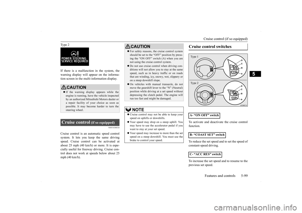
To activate and deactivate the cruise control function. To reduce the set speed and to set the speed of constant-speed driving. To increase the set speed and to resume to the previous set speed.
CAUTION If the warning display appears while the engine is running, have the vehicle inspected by an authorized Mitsubishi Motors dealer ora repair facility of
your choice as soon as
possible. It may become harder to turn the steering wheel.
Cruise control
(if so equipped)
CAUTION For safety reasons, the cruise control system should be set to the “OFF” position by press- ing the “ON OFF” switch (A) when you are not using the cruise control system. Do not use cruise control when driving con- ditions will not allow you to stay at the same speed, such as in heavy traffic or on roadsthat are winding, icy, snowy, wet, slippery or on a steep downhill slope. On vehicles with manual transaxle, do not move the gearshift lever to the “N” (Neutral) position while driving at a set speed withoutdepressing the clutch pedal. The engine will run too fast and might be damaged. NOTE
Cruise control may not be able to keep your speed on uphills or downhills. Your speed may drop on a steep uphill. You may have to use the accelerator pedal if you want to stay at your set speed. Your speed may increase to more than the set speed on a steep downhill. You must use the brake to control your speed.
Cruise control switches
A- “ON OFF” switch B- “COAST SET” switch C- “ACC RES” switchType 1 Type 2
Page 173 of 434
Tire pressure monitoring system 5-106 Features and controls
5
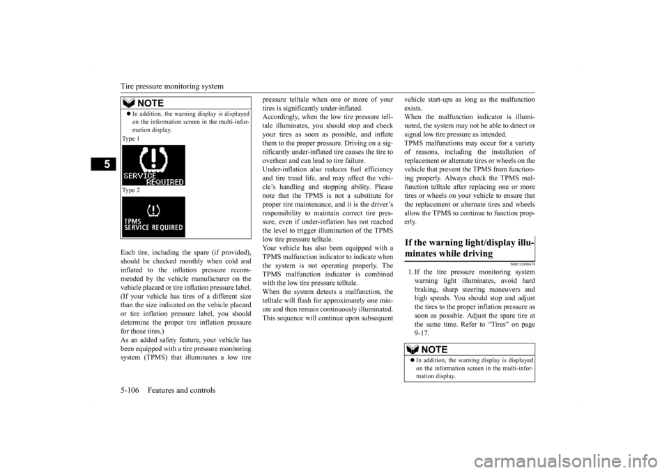
Each tire, including the spare (if provided), should be checked monthly when cold andinflated to the inflation pressure recom-mended by the vehicle manufacturer on the vehicle placard or tire inflation pressure label. (If your vehicle has tires of a different sizethan the size indicated on the vehicle placard or tire inflation pressure label, you should determine the proper tire inflation pressurefor those tires.) As an added safety feature, your vehicle has been equipped with a tire pressure monitoringsystem (TPMS) that illuminates a low tire
pressure telltale when one or more of your tires is significantly under-inflated. Accordingly, when the low tire pressure tell- tale illuminates, you should stop and checkyour tires as soon as possible, and inflate them to the proper pressure. Driving on a sig- nificantly under-inflated tire causes the tire tooverheat and can lead to tire failure. Under-inflation also reduces fuel efficiency and tire tread life, and may affect the vehi-cle’s handling and stopping ability. Pleasenote that the TPMS is not a substitute for proper tire maintenance, and it is the driver’s responsibility to maintain correct tire pres-sure, even if under-inflation has not reached the level to trigger illumination of the TPMS low tire pressure telltale.Your vehicle has also been equipped with a TPMS malfunction indicator to indicate when the system is not operating properly. TheTPMS malfunction indicator is combined with the low tire pressure telltale. When the system detects a malfunction, thetelltale will flash for approximately one min- ute and then remain continuously illuminated. This sequence will continue upon subsequent
vehicle start-ups as long as the malfunction exists. When the malfunction indicator is illumi- nated, the system may not be able to detect orsignal low tire pressure as intended. TPMS malfunctions may occur for a variety of reasons, including the installation ofreplacement or alternate tires or wheels on the vehicle that prevent the TPMS from function- ing properly. Always check the TPMS mal-function telltale after replacing one or moretires or wheels on your vehicle to ensure that the replacement or alternate tires and wheels allow the TPMS to continue to function prop-erly.
N00532800439
1. If the tire pressure monitoring system warning light illuminates, avoid hard braking, sharp steering maneuvers andhigh speeds. You should stop and adjust the tires to the proper inflation pressure as soon as possible. Adjust the spare tire atthe same time. Refer to “Tires” on page 9-17.
NOTE
In addition, the warning display is displayed on the information screen in the multi-infor- mation display.
Type 1 Type 2
If the warning light/display illu- minates while driving
NOTE
In addition, the warning display is displayed on the information screen in the multi-infor- mation display.
Page 178 of 434
Instrument cluster
Features and controls 5-111
5
N00519200276
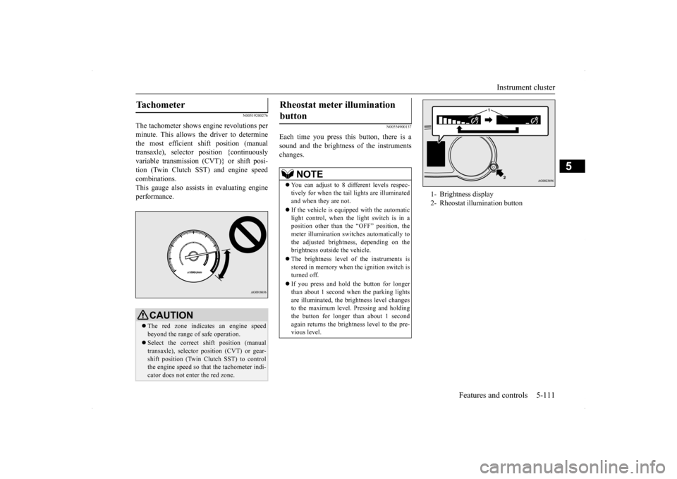
The tachometer shows engine revolutions per minute. This allows the driver to determinethe most efficient shift position (manual transaxle), selector position {continuously variable transmission (CVT)} or shift posi-tion (Twin Clutch SST) and engine speed combinations. This gauge also assists in evaluating engineperformance.
N00554900137
Each time you press this button, there is asound and the brightness of the instruments changes.
Tachometer
CAUTION The red zone indicates an engine speed beyond the range of safe operation. Select the correct shift position (manual transaxle), selector position (CVT) or gear- shift position (Twin Clutch SST) to control the engine speed so that the tachometer indi-cator does not enter the red zone.
Rheostat meter illumination button
NOTE
You can adjust to 8 different levels respec- tively for when the tail
lights are illuminated
and when they are not. If the vehicle is equipped with the automatic light control, when the light switch is in a position other than the “OFF” position, themeter illumination switches automatically to the adjusted brightness, depending on the brightness outside the vehicle. The brightness level of the instruments is stored in memory when the ignition switch isturned off. If you press and hold the button for longer than about 1 second when the parking lights are illuminated, the brightness level changes to the maximum level. Pressing and holdingthe button for longer than about 1 second again returns the brightness level to the pre- vious level.
1- Brightness display 2- Rheostat illumination button