ESP MITSUBISHI LANCER 2016 8.G Workshop Manual
[x] Cancel search | Manufacturer: MITSUBISHI, Model Year: 2016, Model line: LANCER, Model: MITSUBISHI LANCER 2016 8.GPages: 392, PDF Size: 13.12 MB
Page 348 of 392

Emission-control system maintenance 9-22 Vehicle care and maintenance
9
N00940800201
Your vehicle is equipped with an emission- control system that meets all the requirementsof the U.S. Environmental Protection Agency and Environment Canada. The emission-con- trol system is made of: a positive crankcase ventilation system an evaporative emission-control system an exhaust emission-control system
The maintenance services listed in the “WARRANTY AND MAINTENANCE MANUAL” must be performed at the timesor mileages listed to keep the emission-con- trol system working properly. These, and all the other “general” maintenance serviceslisted in this manual, need to be performed to keep your vehicle running properly and reli- ably. You may need more frequent maintenance if you drive your vehicle in harsh conditions such as dusty areas or do a lot of start-and- stop driving. To be sure the emission-control system works properly, have your vehicle inspected and maintained by an authorized Mitsubishi Motors dealer or a repair facility of your
choice following the schedule in the “WAR- RANTY AND MAINTENANCE MAN- UAL”. You should also have an inspection and ser-vice any time you suspect a malfunction.
N00940900215
Spark plugs must fire properly for goodengine performance and emission-control. Do not reuse them by cleaning or regapping. Change them at the mileage listed in the“WARRANTY AND MAINTENANCE MANUAL”.
N00941000037
Check the hose surfaces for any heat and mechanical damage, hard and brittle rubber, cracking, tears, cuts and abrasions. Pay spe- cial attention to the hoses closest to high heatsources such as the exhaust manifold. Check all the hose connections, such as clamps and couplings, to make sure they are secure andthat there are no leaks. If you see any wear or damage, replace the hoses immediately.
N00950100050
Have the valve clearance checked at anauthorized Mitsubishi Motors dealer at the mileage specified in the “WARRANTY ANDMAINTENANCE MANUAL”. If the engine sounds abnormally loud, have adjustments made by an authorizedMitsubishi Motors dealer.
Emission-control system maintenance
NOTE
To meet government regulations and pro- mote cleaner air, your vehicle is equipped with an onboard diagnostic system (OBD).The engine electronic control module that controls OBD functions stores various data (especially about the exhaust emissions).This data will be erased if the battery cable is disconnected, which could make a rapid diagnosis difficult. Do not disconnect thebattery cable when the engine malfunction indicator (“SERVICE ENGINE SOON” or “Check engine light”) is on.
Spark plugs
NOTE
Use the spark plugs listed under “Engine specifications” on page 11-5 or plugs that are exactly the same. Other plugs could cause engine damage, performance problems or radio noise.
Fuel hoses Intake valve clearance
BK0230300US.bo
ok 22 ページ 2015年7月30日 木曜日 午後8時38分
Page 353 of 392

Fuses
Vehicle care and maintenance 9-27
9
* - Fusible link Some fuses may not be installed on your vehicle, depending on the vehicle model or specifications. The table above shows the main equip- ment corresponding to each fuse. 20
Power window con-
trol
30 A
*
21 Defogger 30 A
*
22
Heated
outside rearview
mirrors
7.5 A
23 115V Power outlet 15 A 24 Power seats
25 (20) A
25 Heated seats 30 ANo.
Sym- bol
Electrical system
Capac-ity
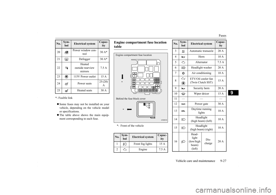
Engine compartment fuse location table * - Front of the vehicle
No.
Sym- bol
Electrical system
Capac-ity
1 Front fog lights 15 A 2 Engine 7.5 AEngine compartment fuse location
*
Behind the fuse block cover
*
3 Automatic transaxle 20 A 4 Horn 10 A 5 Alternator 7.5 A 6 Headlight washer 20 A 7 Air conditioning 10 A 8
/ ETV/Oil cooler fan
(Twin Clutch SST)
15 A
9 Security horn 20 A 10 Wiper deicer 15 A 11 — — — 13
Daytime running
lights
10 A
14
Headlight
(high beam) (left)
10 A
15
Headlight
(high beam) (right)
10 A
16
Head- light (low/high beam) (left)
Dis- charge
20 A
No.
Sym- bol
Electrical system
Capac-ity
BK0230300US.bo
ok 27 ページ 2015年7月30日 木曜日 午後8時38分
Page 354 of 392

Fuses 9-28 Vehicle care and maintenance
9
* - Fusible link Some fuses may not be installed on your vehicle, depending on the vehicle modelor specifications. The table above shows the main equip- ment corresponding to each fuse.
There are no 7.5 A, 25 A or 30 A spare fuses. If a fuse of one of these capacities blows,replace it temporarily by borrowing one of the fuses indicated below. 7.5 A: 10 A spare fuse25 A: 20 A spare fuse 30 A: 30 A audio amplifier fuse
Replace the borrowed fuse with a fuse that has the correct capacity as soon as possible.
N00954900027
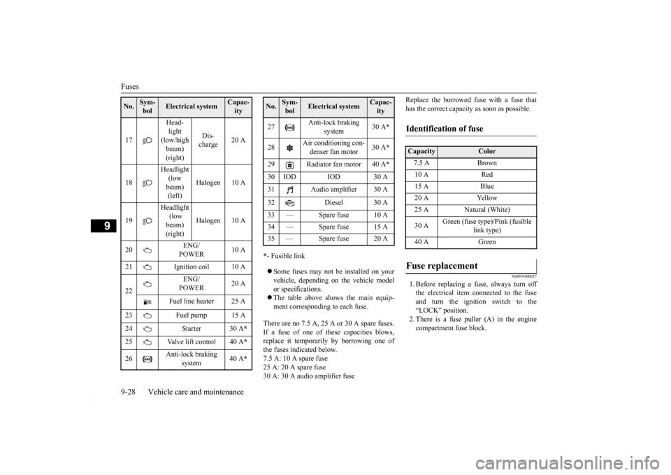
1. Before replacing a fuse, always turn offthe electrical item connected to the fuseand turn the ignition switch to the“LOCK” position. 2. There is a fuse puller (A) in the engine compartment fuse block.
17
Head- light (low/high beam) (right)
Dis- charge
20 A
18
Headlight (low beam) (left)
Halogen 10 A
19
Headlight (low beam) (right)
Halogen 10 A
20
ENG/ POWER
10 A
21 Ignition coil 10 A 22
ENG/ POWER
20 A
Fuel line heater 25 A
23 Fuel pump 15 A 24 Starter 30 A
*
25 Valve lift control 40 A
*
26
Anti-lock braking
system
40 A
*
No.
Sym- bol
Electrical system
Capac-ity
27
Anti-lock braking
system
30 A
*
28
Air conditioning con- denser fan motor
30 A
*
29 Radiator fan motor 40 A
*
30 IOD IOD 30 A31 Audio amplifier 30 A 32 Diesel 30 A 33 — Spare fuse 10 A 34 — Spare fuse 15 A35 — Spare fuse 20 ANo.
Sym- bol
Electrical system
Capac-ity
Identification of fuse Capacity
Color
7.5 A Brown10 A Red15 A Blue20 A Yellow25 A Natural (White) 30 A
Green (fuse type)/Pink (fusible
link type)
40 A Green
Fuse replacement
BK0230300US.bo
ok 28 ページ 2015年7月30日 木曜日 午後8時38分
Page 359 of 392

Replacement of light bulbs
Vehicle care and maintenance 9-33
9
N00943100885
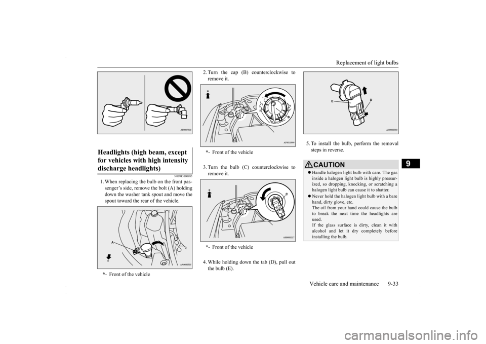
1. When replacing the bulb on the front pas- senger’s side, remove the bolt (A) holdingdown the washer tank spout and move thespout toward the rear of the vehicle.
2. Turn the cap (B) counterclockwise to remove it. 3. Turn the bulb (C) counterclockwise to remove it. 4. While holding down
the tab (D), pull out
the bulb (E).
5. To install the bulb, perform the removal steps in reverse.
Headlights (high beam, except for vehicles with high intensity discharge headlights) * - Front of the vehicle
*- Front of the vehicle * - Front of the vehicle
CAUTIONHandle halogen light bulb with care. The gas inside a halogen light bulb is highly pressur- ized, so dropping, knocking, or scratching a halogen light bulb can cause it to shatter. Never hold the halogen light bulb with a bare hand, dirty glove, etc.The oil from your hand could cause the bulb to break the next time the headlights are used.If the glass surface is dirty, clean it with alcohol and let it dry completely before installing the bulb.
BK0230300US.bo
ok 33 ページ 2015年7月30日 木曜日 午後8時38分