low oil pressure MITSUBISHI LANCER EVOLUTION 2007 Service User Guide
[x] Cancel search | Manufacturer: MITSUBISHI, Model Year: 2007, Model line: LANCER EVOLUTION, Model: MITSUBISHI LANCER EVOLUTION 2007Pages: 1449, PDF Size: 56.82 MB
Page 453 of 1449

ENGINE -Engine Assembly11A-47
AD"ENGINE ASSEMBLY REMOVAL
After checking that all the cables, hoses, and harness
connectors have been disconnected, lift the engine with a
chain block slowly and remove the engine assembly located
at the upper engine room.
INSTALLATION SERVICE POINTS
"AAENGINE ASSEMBLY INSTALLATION
Install the engine assembly while checking that none of cables,
hoses, or harness connectors, etc. has been engaged.
"BAENGINE MOUNTING BRACKET AND STOPPER
ASSEMBLY INSTALLATION
1. Support the engine oil pan with a garage jack via a block
of wood cut adjusting the engine position and install the
engine mounting bracket and stopper assembly. Position
the engine mounting stopper so that a mark indicated
by an arrow can face the direction shown in the illustration.
2. Support engine with garage jack.
3. Remove the chain block and hold the engine assembly
with the special tool.(Tool used for removal of transmission
assembly)
"CAO-RING/FUEL HIGH PRESSURE HOSE
INSTALLATION
1. Apply small quantity of new engine oil on O-ring.
Caution
Do not let engine oil get into the delivery pipe.
2. Install the fuel high pressure pipe to the delivery pipe
rotating in both directions without damaging the O-ring
and check that it rotates smoothly.
3. In case of not rotating smoothly, remove the fuel high
pressure hose and insert it to the delivery pipe again
after checking damage of the O-ring since there is a
possibility of O-ring engagement.
4. Tighten fuel high pressure hose mounting bolt to the
specified torque.
Tightening Torque: 5.0±1.0 N·m
Engine mounting stopper
Engine side
Page 462 of 1449

ENGINE OVERHAUL -Specifications11B-8
SEALANTS
ItemSpecified sealantQuantity
Engine support bracket bolt3MTMAAD Part No. 8672 or equivalentAs required
Semi-circular packing3MTMAAD Part No. 8672 or equivalentAs required
Rocker cover3MTMAAD Part No. 8672 or equivalentAs required
Water outlet fittingMitsubishi Genuine Part No. MD970389 or
equivalentAs required
Engine coolant temperature gauge unit3MTMAAD Part No. 8672 or equivalentAs required
Engine coolant temperature sensor3MTMAAD Part No. 8672 or equivalentAs required
Cylinder head (camshaft bearing cap mounting
section)3MTMAAD Part No. 8672 or equivalentAs required
Cam position sensor supportMitsubishi Genuine Part No. MD970389 or
equivalentAs required
Oil pressure switch3MTMAAD Part No. 8672 or equivalentAs required
Oil panMitsubishi Genuine Part No. MD970389 or
equivalentAs required
Oil seal caseMitsubishi Genuine Part No. MD970389 or
equivalentAs required
FORM-IN-PLACE-GASKET
FIPG is used for several members of this engine. With this gasket, caution is required to the application
amount, application procedure and state of the application surface so that the performance is sufficiently
attained.
If sufficient gasket is not applied, leaks could occur, and if too much is applied, the gasket could protrude
and plug or restrict the oil and water flow passage. Thus, to prevent leaks from the joined sections,
it is absolutely necessary to evenly apply the correct amount.
The FIPG used for the engine parts reacts with moisture in the air and hardens so use it for the normal
metal flange parts.
DISASSEMBLY
The parts assembled with FIPG can be easily disassembled without special means. However, in some
cases, the sealant on the seams must be broken by lightly tapping with a wood hammer or similar tool.
A smooth and thin gasket scraper can be lightly tapped into the seams but in this case, take care not
to damage the seams.
The special tool oil pan remover (MD998727) is set for this purpose.
WASHING THE GASKET SURFACE
Completely remove all matters adhered on the gasket surfaces with a gasket scraper or wire brush.
Confirm that the FIPG application surface is smooth. There must be no grease or foreign matter on
the gasket surface.
Always remove the old FIPG that has entered the mounting holes and screw holes.
APPLICATION PROCEDURES
Apply an even coat of FIPG within the predetermined radius. Completely cover the areas around the
mounting holes. The FIPG can be wiped off if it has not hardened. Install at the set position while the
FIPG is still wet (within 15 minutes). When installing, maker sure that the FIPG does not get on areas
other than the required areas. After installing, do not subject the application areas to oil or water or
start the engine until the FIPG has sufficiently hardened (approx. one hour). The FIPG application procedures
differ according to the member, so follow the procedures given in this manual and apply the FIPG.
Page 529 of 1449
ENGINE LUBRICATION -On-vehicle Service12-5
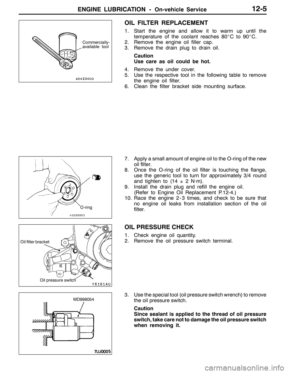
OIL FILTER REPLACEMENT
1. Start the engine and allow it to warm up until the
temperature of the coolant reaches 80_Cto90_C.
2. Remove the engine oil filler cap.
3. Remove the drain plug to drain oil.
Caution
Use care as oil could be hot.
4. Remove the under cover.
5. Use the respective tool in the following table to remove
the engine oil filter.
6. Clean the filter bracket side mounting surface.
7. Apply a small amount of engine oil to the O-ring of the new
oil filter.
8. Once the O-ring of the oil filter is touching the flange,
use the generic tool to turn for approximately 3/4 round
and tighten to (14±2 N·m).
9. Install the drain plug and refill the engine oil.
(Refer to Engine Oil Replacement P.12-4.)
10. Race the engine 2 - 3 times, and check to be sure that
no engine oil leaks from installation section of the oil
filter.
OIL PRESSURE CHECK
1. Check engine oil quantity.
2. Remove the oil pressure switch terminal.
3. Use the special tool (oil pressure switch wrench) to remove
the oil pressure switch.
Caution
Since sealant is applied to the thread of oil pressure
switch, take care not to damage the oil pressure switch
when removing it.
Commercially-
available tool
O-ring
Oil pressure switch
Oil filter bracket
MD998054
Page 535 of 1449

MPI -General Information13A-3
GENERAL INFORMATION
The Multipoint Fuel Injection System consists
of sensors which detect the engine conditions,
the engine-ECU which controls the system
based on signals from these sensors, and
actuators which operate under the control of
the engine-ECU. The engine-ECU carries outactivities such as fuel injection control, idle
speed control and ignition timing control. In
addition, the engine-ECU is equipped with
several diagnosis modes which simplify
troubleshooting when a problem develops.
FUEL INJECTION CONTROL
The injector drive times and injector timing are
controlled so that the optimum air/fuel mixture
is supplied to the engine to correspond to the
continually-changing engine operation condi-
tions.
A single injector is mounted at the intake port
of each cylinder. Fuel is sent under pressure
from the fuel tank by the fuel pump, with the
pressure being regulated by the fuel pressure
regulator. The fuel thus regulated is distributed
to each of the injectors.
Fuel injection is normally carried out once for
each cylinder for every two rotations of the
crankshaft. The firing order is 1-3-4-2. This iscalled sequential fuel injection. The
engine-ECU provides a richer air/fuel mixture
by carrying out “open-loop” control when the
engine is cold or operating under high load
conditions in order to maintain engine
performance. In addition, when the engine is
warm or operating under normal conditions,
the engine-ECU controls the air/fuel mixture
by using the oxygen sensor signal to carry out
“closed-loop” control in order to obtain the
theoretical air/fuel mixture ratio that provides
the maximum cleaning performance from the
three way catalyst.
IDLE AIR CONTROL
The idle speed is kept at the optimum speed
by controlling the amount of air that bypasses
the throttle valve in accordance with changes
in idling conditions and engine load during
idling. The engine-ECU drives the idle speed
control motor to keep the engine running at
the pre-set idle target speed in accordance
with the engine coolant temperature and airconditioner load. In addition, when the air
conditioner switch is turned off and on while
the engine is idling, the idle speed control motor
operates to adjust the throttle valve bypass
air amount in accordance with the engine load
conditions in order to avoid fluctuations in the
engine speed.
IGNITION TIMING CONTROL
The power transistor located in the ignition
primary circuit turns ON and OFF to control
the primary current flow to the ignition coil. This
controls the ignition timing in order to provide
the optimum ignition timing with respect to theengine operating conditions. The ignition timing
is determined by the engine-ECU from the
engine speed, intake air volume, engine coolant
temperature and barometric pressure.
SELF-DIAGNOSIS FUNCTION
DWhen an abnormality is detected in one
of the sensors or actuators related to
emission control, the engine warning lamp
(check engine lamp) illuminates as a
warning to the driver.
DWhen an abnormality is detected in one
of the sensors or actuators, a diagnosis
code corresponding to the abnormality is
output.DThe RAM data inside the engine-ECU that
is related to the sensors and actuators can
be read by means of the MUT-II. In addition,
the actuators can be force-driven under
certain circumstances.
Page 537 of 1449

MPI -General Information13A-5
MULTI-POINT FUEL INJECTION SYSTEM DIAGRAM
L1 Oxygen sensor (front)
L2 Oxygen sensor (rear)
L3 Air flow sensor
L4 Intake air temperature sensor
L5 Throttle position sensor
L6 Camshaft position sensor
L7 Crank angle sensor
L8 Barometric pressure sensor
L9 Engine coolant temperature sensor
L10 Detonation sensor
Engine-ECU
l1 Injector
l2 Idle speed control servo
l3 Fuel pressure control solenoid valve
l4 Waste gate solenoid valve
l5 EGR control solenoid valve
l6 Purge control solenoid valve
l7 Secondary air control solenoid valve
DPower supply
DIgnition switch IG
DIgnition switch ST
DVehicle speed sensor
DA/C switch
DA/C load signal
DTachometer
DPower steering fluid pressure switch
DAlternator FR terminal
DDiagnosis control terminal
DIntercooler water spray switch (automatic)
DIntercooler water spray switch (manual)DEngine control relay
DFuel pump relay 2, 3
DA/C relay
DIgnition coil
DFan controller
DCondenser fan relay (HI)
DCondenser fan relay (LOW)
DEngine warning lamp
DDiagnosis output
DAlternator G terminal
DIntercooler water spray relay
DIntercooler water spray lamp
L1 Oxygen
sensor
(front)
L4 Intake air
temperature
sensorL5 Throttle
position
sensor
L6 Camshaft
position sensorl1 Injector l2 Idle
speed
control
servo
l6 Purge
control
solenoid
valve
Three-way
catalytic converter Canister
Air
inletVacuum
tank
Fuel
pressure
reguratorFrom
fuel tank
To fuel tank
PCV valveFrom
fuel pump
Waste gate
actuatorL2 Oxygen sensor (rear) Check
valveBy-pass
valve
l5 EGR control
solenoid valve
l4 Waste gate
solenoid valve L8 Barometric
pressure
sensor
L3 Air flow
sensorl7 Secondary
air control
solenoid
valve
Secondary
air valvel3 Fuel pressure
control
solenoid valve
EGR
valve
L9 Engine coolant
temperature sensor
L7 Crank angle sensor
L10 Detonation sensor
Page 580 of 1449
MPI -Troubleshooting13A-48
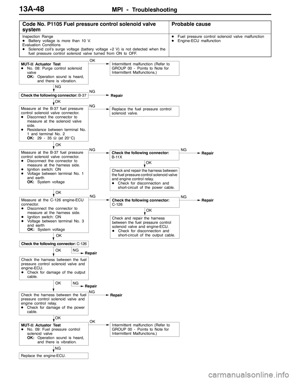
Code No. P1105 Fuel pressure control solenoid valve
systemProbable cause
Inspection Range
DBattery voltage is more than 10 V.
Evaluation Conditions
DSolenoid coil’s surge voltage (battery voltage +2 V) is not detected when the
fuel pressure control solenoid valve turned from ON to OFF.DFuel pressure control solenoid valve malfunction
DEngine-ECU malfunction
OK
NG
Replace the engine-ECU.
OKIntermittent malfunction (Refer to
GROUP 00 - Points to Note for
Intermittent Malfunctions.)MUT-IIActuator Test
DNo. 09: Fuel pressure control
solenoid valve
OK:Operation sound is heard,
and there is vibration.OKNG
Repair
OK
NG
Intermittent malfunction (Refer to
GROUP 00 - Points to Note for
Intermittent Malfunctions.)
OK
Check the following connector:B-37
MUT-IIActuator Test
DNo. 08: Purge control solenoid
valve
OK:Operation sound is heard,
and there is vibration.
NG
Repair
NGNG
Repair
OK
OK
Check and repair the harness
between the fuel pressure control
solenoid valve and engine-ECU.
DCheck for disconnection and
short-circuit of the output cable.
Check the following connector:
C-126
OK
Check the following connector:C-126
Measure at the C-126 engine-ECU
connector.
DDisconnect the connector to
measure at the harness side.
DIgnition switch: ON
DVoltage between terminal No. 3
and earth
OK:System voltageNG
Replace the fuel pressure control
solenoid valve.Measure at the B-37 fuel pressure
control solenoid valve connector.
DDisconnect the connector to
measure at the solenoid valve
side.
DResistance between terminal No.
1 and terminal No. 2
OK:29 - 35Ω(at 20_C)
OK
NG
Measure at the B-37 fuel pressure
control solenoid valve connector.
DDisconnect the connector to
measure at the harness side.
DIgnition switch: ON
DVoltage between terminal No. 1
and earth
OK:System voltage
OKNG
Repair
OK
OKCheck and repair the harness between
the fuel pressure control solenoid valve
and engine control relay.
DCheck for disconnection and
short-circuit of the power cable.
Check the following connector:
B-11X
NG
RepairCheck the harness between the fuel
pressure control solenoid valve and
engine control relay.
DCheck for damage of the power
cable.NG
Repair
OK
Check the harness between the fuel
pressure control solenoid valve and
engine-ECU.
DCheck for damage of the output
cable.
Page 594 of 1449
MPI -Troubleshooting13A-62
NG
Check for the entry of foreign matter (water, kerosene, etc.) in fuel.
Check the trouble symptoms.OK
End
NG
Replace the engine-ECU.
Check the trouble symptoms.OK
End
OK
Replace the injectors for all cylinders.
Check the harness and connector between each cylinder’s injector
and engine-ECU for disconnection, short-circuit or damage.NG
Repair
OK
Check the fuel pressure. (Refer to P.13A-128.)
OK
Check the EGR valve for sticking.
(Refer to GROUP 17 - Exhaust Gas Purifier Check.)NGReplace the EGR valve.
OK
Check the compression pressure.
(Refer to GROUP 11 - Engine Adjustment.)NG
Repair
OK
Check the harness and connectors between the ignition coil and
body earth and between the engine-ECU and ignition coil for
disconnection, short-circuit or damage.NG
Repair
OK
Check the ignition coil parts.
(Refer to GROUP 16 - Ignition Device.)NGReplace the ignition coil.
OK
Check the following connectors:B-103, B-119NG
Repair
OK
Check the spark plug. (Refer to GROUP 16 - Ignition Device.)NGReplace the spark plug.
OK
Check the spark plug cable.
(Refer to GROUP 16 - Ignition Device.)NGReplace the spark plug cable.
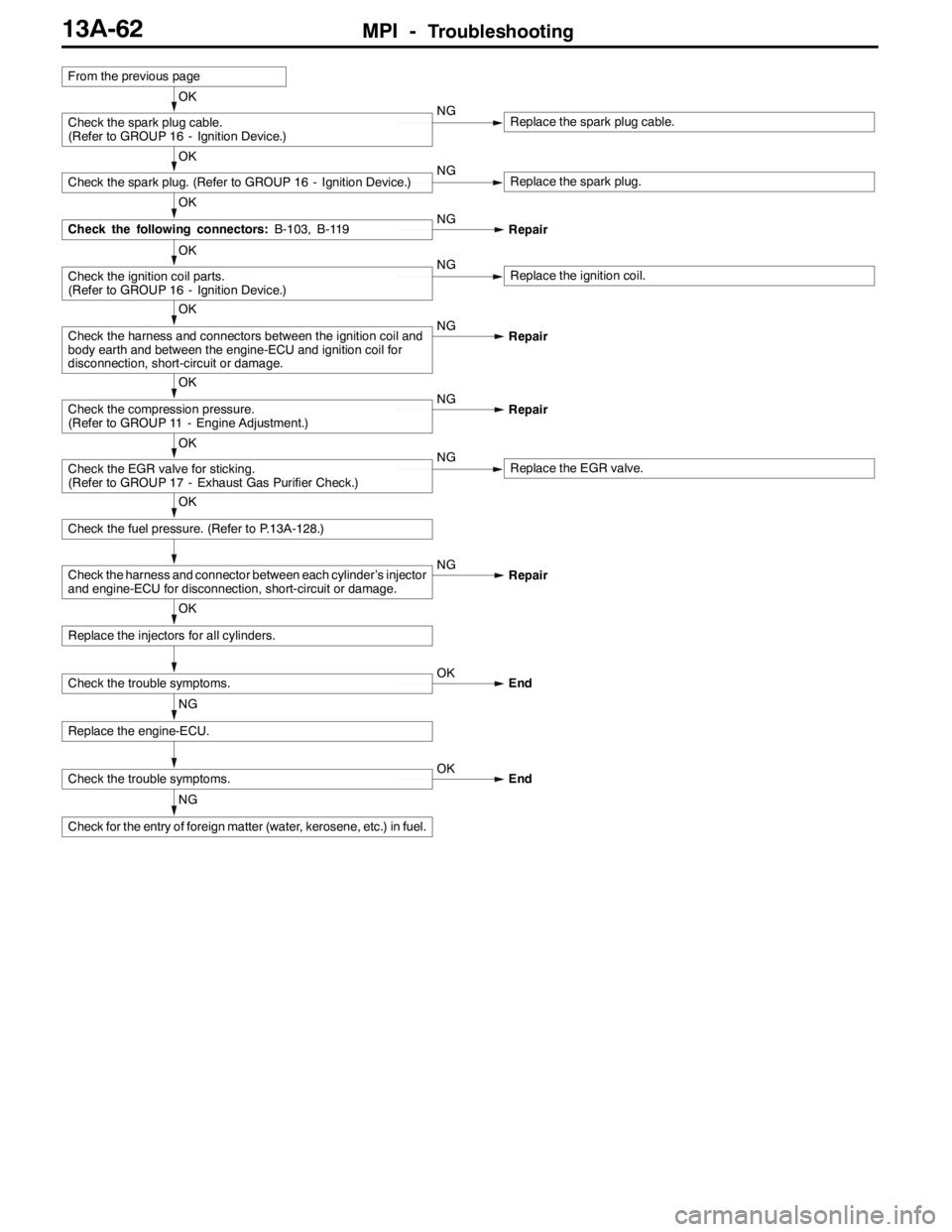
From the previous page
Page 597 of 1449
MPI -Troubleshooting13A-65
NG
Check for the entry of foreign matter (water, kerosene, etc.) in fuel.
Check the trouble symptoms.OK
End
NG
Replace the engine-ECU.
Check the trouble symptoms.OK
End
OK
Replace the injector for each cylinder.
OK
Check the harness and connector between each cylinder’s injector
and engine-ECU for disconnection, short-circuit or damage.NG
Repair
OK
Check the fuel pressure. (Refer to P.13A-118.)
OK
Check the EGR valve for sticking.
(Refer to GROUP 17 - Exhaust Gas Purifier Check.)NGReplace the EGR valve.
OK
Check the EGR control solenoid valve.
(Refer to GROUP 17 - Exhaust Gas Purifier Check.)NGReplace the EGR control solenoid valve.
OK
Check the purge control solenoid valve.
(Refer to GROUP 17 - Exhaust Gas Purifier Check.)NGReplace the purge control solenoid valve.
OK
Check the compression pressure.
(Refer to GROUP 11 - Engine Adjustment.)NG
Repair
OK
Check the harness and connector between each cylinder’s ignition
coil and body earth and between engine-ECU and ignition coil for
disconnection, short-circuit or damage.NG
Repair
OK
Check the ignition coil parts.
(Refer to GROUP 16 - Ignition Device.)NGReplace the ignition coil.
OK
Check the following connectors:B-114, B-119NG
Repair
OK
Check the spark plug. (Refer to GROUP 16 - Ignition Device.)NGReplace the spark plug.
OK
Check the spark plug cable.
(Refer to GROUP 16 - Ignition Device.)NGReplace the spark plug cable.
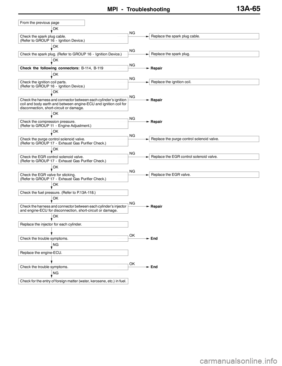
From the previous page
Page 601 of 1449
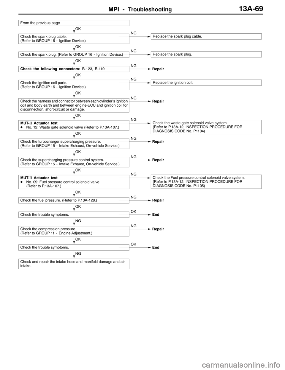
MPI -Troubleshooting13A-69
NG
Check and repair the intake hose and manifold damage and air
intake.
OK
Check the trouble symptoms.OK
End
NG
Check the compression pressure.
(Refer to GROUP 11 - Engine Adjustment.)NG
Repair
OK
Check the trouble symptoms.OK
End
OK
Check the fuel pressure. (Refer to P.13A-128.)NG
Repair
OK
MUT-IIActuator test
DNo. 09: Fuel pressure control solenoid valve
(Refer to P.13A-107.)NGCheck the Fuel pressure control solenoid valve system.
(Refer to P.13A-12, INSPECTION PROCEDURE FOR
DIAGNOSIS CODE No. P1105)
OK
Check the supercharging pressure control system.
(Refer to GROUP 15 - Intake Exhaust, On-vehicle Service.)NG
Repair
OK
Check the turbocharger supercharging pressure.
(Refer to GROUP 15 - Intake Exhaust, On-vehicle Service.)NG
Repair
OK
MUT-IIActuator test
DNo. 12: Waste gate solenoid valve (Refer to P.13A-107.)NGCheck the waste gate solenoid valve system.
(Refer to P.13A-12, INSPECTION PROCEDURE FOR
DIAGNOSIS CODE No. P1104)
OK
Check the harness and connector between each cylinder’s ignition
coil and body earth and between engine-ECU and ignition coil for
disconnection, short-circuit or damage.NG
Repair
OK
Check the ignition coil parts.
(Refer to GROUP 16 - Ignition Device.)NGReplace the ignition coil.
OK
Check the following connectors:B-123, B-119NG
Repair
OK
Check the spark plug. (Refer to GROUP 16 - Ignition Device.)NGReplace the spark plug.
OK
Check the spark plug cable.
(Refer to GROUP 16 - Ignition Device.)NGReplace the spark plug cable.
From the previous page
Page 662 of 1449

MPI -On-vehicle Service13A-130
14. If any of fuel pressure measured in steps 10 to 13 is out of
specification, troubleshoot and repair according to the
table below.
SymptomProbable causeRemedy
DFuel pressure too low
DFuelpressuredropsafterracing
Clogged fuel filterReplace fuel filter
DFuelpressuredrops after racing
DNo fuel pressure in fuel return
hose
Fuel leaking to return side due to poor
fuel regulator valve seating or settled
springReplace fuel pressure regulator
Low fuel pump delivery pressureReplace fuel pump
Fuel pressure too highBinding valve in fuel pressure
regulatorReplace fuel pressure regulator
Clogged fuel return hose or pipeClean or replace hose or pipe
Same fuel pressure when vacuum
hose is connected and when
disconnected
Damaged vacuum hose or clogged
nippleReplace vacuum hose or clean nipple
disconnectedFuel pressure control system
malfunctionCheck the fuel pressure control
system
15. Stop the engine and check change of fuel pressure gauge
reading. Normal if the reading does not drop within 2
minutes. If it does, observe the rate of drop and
troubleshoot and repair according to the table below.
SymptomProbable causeRemedy
Fuel pressure drops gradually after
engineisstopped
Leaky injectorReplace injector
engineisstopped
Leaky fuel regulator valve seatReplace fuel pressure regulator
Fuel pressure drops sharply
immediately after engine is stoppedCheck valve in fuel pump is held openReplace fuel pump
16. Release residual pressure from the fuel pipe line.
(Refer to P.13A-125.)
17. Remove the fuel pressure gauge and special tool from
the delivery pipe.
Caution
Cover the hose connection with rags to prevent splash
of fuel that could be caused by some residual pressure
in the fuel pipe line.
18. Replace the O-ring at the end of the fuel high pressure
hose with a new one. Furthermore, apply engine oil to
the new O-ring before replacement.
19. Fit the fuel high pressure hose over the delivery pipe
and tighten the bolt to specified torque.
Tightening torque: 5.0±1.0 N·m
20. Check for any fuel leaks by following the procedure in
step 7.
21. Disconnect the MUT-II.