sensor MITSUBISHI LANCER EVOLUTION 2007 Service Repair Manual
[x] Cancel search | Manufacturer: MITSUBISHI, Model Year: 2007, Model line: LANCER EVOLUTION, Model: MITSUBISHI LANCER EVOLUTION 2007Pages: 1449, PDF Size: 56.82 MB
Page 88 of 1449

HOW TO READ THE WIRING DIAGRAMS -Composition and Contents of Wiring DiagramsA-2
COMPOSITION AND CONTENTS OF WIRING DIAGRAMS
(1) This manual consists of wiring harness diagrams, installation locations of individual parts, circuits
diagrams and index.
(2) In each section, all specifications are listed, including optional specifications. Accordingly, some
specifications may not be applicable for individual vehicles.
SectionBasic contents
Wiring harness
configuration
diagramsConnector locations and harness wiring configurations on actual vehicles are illustrated.
Single part
installation positionLocations are shown for each point of relays, electronic control units, sensors, solenoids,
solenoid valves, diodes, inspection connectors, spare connectors, fusible links, fuses, etc. In the
part’s lists, parts are listed in alphabetical order.
Circuit diagramsCircuits from power supply to earth are shown completely, classified according to system. There
is a main division into power circuits, and circuits classified by system. The circuits classified by
system also include operation and troubleshooting hints.
DJunction block
The entire circuit for the junction block is described, because only the part of the junction
block needed is normally shown in each circuit diagram.
DJoint connectors
The internal circuits for all joint connectors are described, because only the part needed
is shown in each circuit diagram.
DPower supply circuits
Circuits from the battery to fusible link, dedicated fuses, ignition switch, general purpose
fuses, etc.
DCircuits classified by system
For each system, the circuits are shown from fuse to earth, excluding the power supply
sections.
DOperation
The standard operation of each system is briefly described, following the route of current
flow.
DTroubleshooting hints
This is a brief explanation of the inspection points that serve as hints when troubleshooting.
Explanations of the circuits controlled by the electronic control unit are omitted. Refer
to the related publications as required.
IndexAll components used are listed by connector number and component name.
Page 91 of 1449
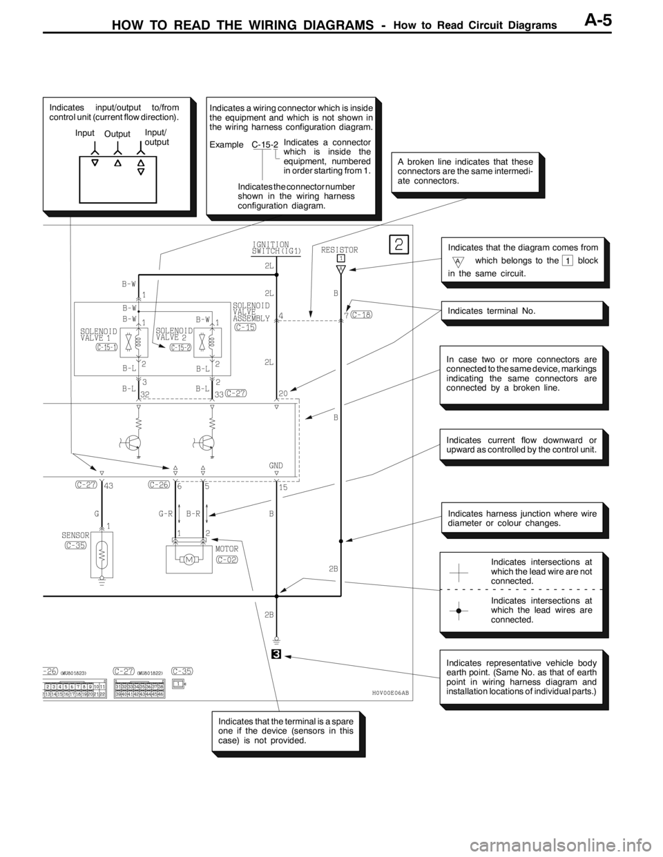
HOW TO READ THE WIRING DIAGRAMS -How to Read Circuit DiagramsA-5
Indicates input/output to/from
control unit (current flow direction).
Input
OutputInput/
output
In case two or more connectors are
connected to the same device, markings
indicating the same connectors are
connected by a broken line.
Indicates current flow downward or
upward as controlled by the control unit.
Indicates harness junction where wire
diameter or colour changes.
Indicates intersections at
which the lead wire are not
connected.
Indicates intersections at
which the lead wires are
connected.
Indicates representative vehicle body
earth point. (Same No. as that of earth
point in wiring harness diagram and
installation locations of individual parts.)
Indicates that the terminal is a spare
one if the device (sensors in this
case) is not provided.
Indicates terminal No.
Indicates that the diagram comes from
Awhich belongs to the block
in the same circuit.1
A broken line indicates that these
connectors are the same intermedi-
ate connectors.
Indicates a wiring connector which is inside
the equipment and which is not shown in
the wiring harness configuration diagram.
Example C-15-2
Indicates the connector number
shown in the wiring harness
configuration diagram.Indicates a connector
which is inside the
equipment, numbered
in order starting from 1.
Page 99 of 1449

B-1
ELECTRICAL
WIRING
CONTENTS
WIRING HARNESS CONFIGURATION
DIAGRAMS 4.........................
OVERALL WIRING DIAGRAM
L.H. drive vehicles 4........................
R.H. drive vehicles 5........................
ENGINE COMPARTMENT
L.H. drive vehicles 6........................
R.H. drive vehicles 8........................
ENGINE AND TRANSMISSION
L.H. drive vehicles 10.......................
R.H. drive vehicles 14.......................
DASH PANEL
L.H. drive vehicles 18.......................
R.H. drive vehicles 24.......................
FLOOR AND ROOF
L.H. drive vehicles 30.......................
R.H. drive vehicles 32.......................
DOOR
L.H. drive vehicles 34.......................
R.H. drive vehicles 36.......................
LUGGAGE COMPARTMENT
L.H. drive vehicles 38.......................
R.H. drive vehicles 39.......................
SINGLE PART INSTALLATION
POSITION 40.........................
RELAY 40.................................
ECU 41...................................
SENSOR 43...............................
SOLENOID VALVE 46......................
INSPECTION CONNECTOR AND SPARE
CONNECTOR 47...........................
FUSIBLE LINK AND FUSE 48..............
EARTH CABLE 49.........................
EARTH 50.................................
CIRCUIT DIAGRAMS 54...............
J/B 54....................................
J/C
L.H. drive vehicles 56.......................
R.H. drive vehicles 62.......................
CENTRALIZED JUNCTION 68..............
POWER DISTRIBUTION SYSTEM 74........
STARTING SYSTEM 79....................
Page 104 of 1449
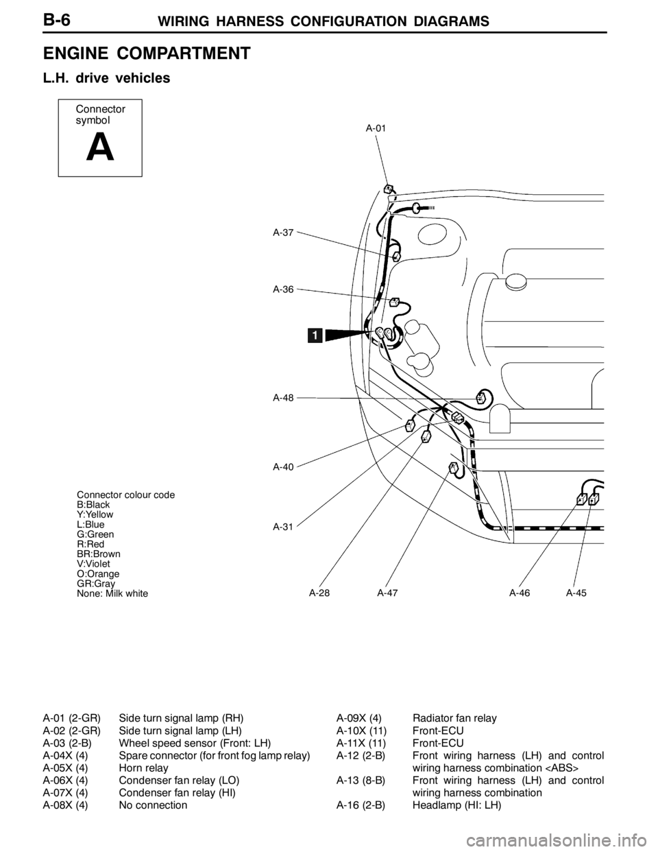
WIRING HARNESS CONFIGURATION DIAGRAMS
Connector
symbol
A
A-01
A-37
A-36
A-48
A-40
A-31
A-28A-47A-46A-45
1
Connector colour code
B:Black
Y:Yellow
L:Blue
G:Green
R:Red
BR:Brown
V:Violet
O:Orange
GR:Gray
None: Milk white
B-6
ENGINE COMPARTMENT
L.H. drive vehicles
A-01 (2-GR) Side turn signal lamp (RH)
A-02 (2-GR) Side turn signal lamp (LH)
A-03 (2-B) Wheel speed sensor (Front: LH)
A-04X (4) Spare connector (for front fog lamp relay)
A-05X (4) Horn relay
A-06X (4) Condenser fan relay (LO)
A-07X (4) Condenser fan relay (HI)
A-08X (4) No connectionA-09X (4) Radiator fan relay
A-10X (11) Front-ECU
A-11X (11) Front-ECU
A-12 (2-B) Front wiring harness (LH) and control
wiring harness combination
A-13 (8-B) Front wiring harness (LH) and control
wiring harness combination
A-16 (2-B) Headlamp (HI: LH)
Page 105 of 1449
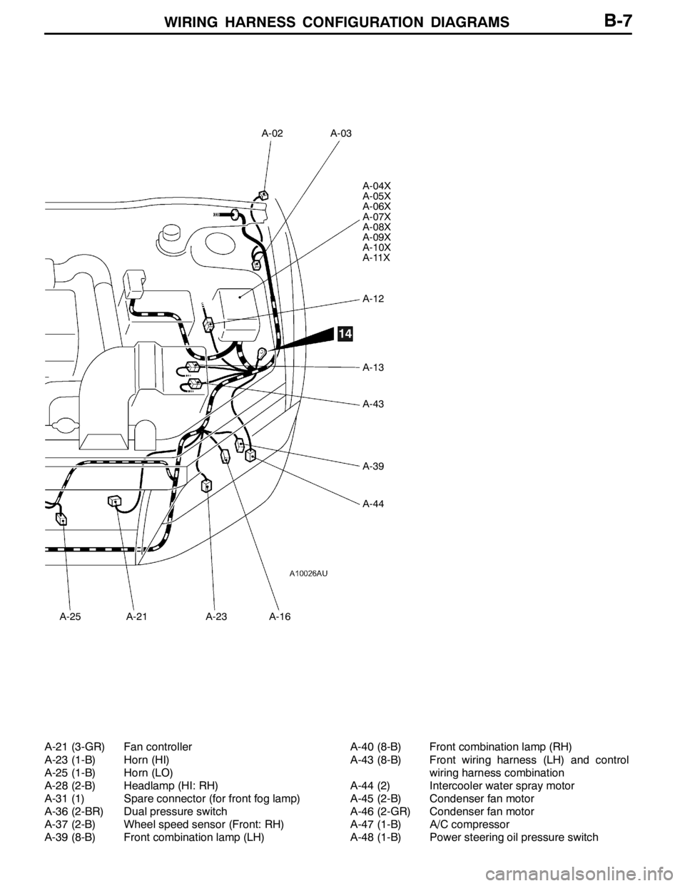
WIRING HARNESS CONFIGURATION DIAGRAMS
A-02
A-25
A-03
A-04X
A-05X
A-06X
A-07X
A-08X
A-09X
A-10X
A-11X
A-12
A-13
A-43
A-39
A-44
A-21A-23A-16
14
B-7
A-21 (3-GR) Fan controller
A-23 (1-B) Horn (HI)
A-25 (1-B) Horn (LO)
A-28 (2-B) Headlamp (HI: RH)
A-31 (1) Spare connector (for front fog lamp)
A-36 (2-BR) Dual pressure switch
A-37 (2-B) Wheel speed sensor (Front: RH)
A-39 (8-B) Front combination lamp (LH)A-40 (8-B) Front combination lamp (RH)
A-43 (8-B) Front wiring harness (LH) and control
wiring harness combination
A-44 (2) Intercooler water spray motor
A-45 (2-B) Condenser fan motor
A-46 (2-GR) Condenser fan motor
A-47 (1-B) A/C compressor
A-48 (1-B) Power steering oil pressure switch
Page 106 of 1449
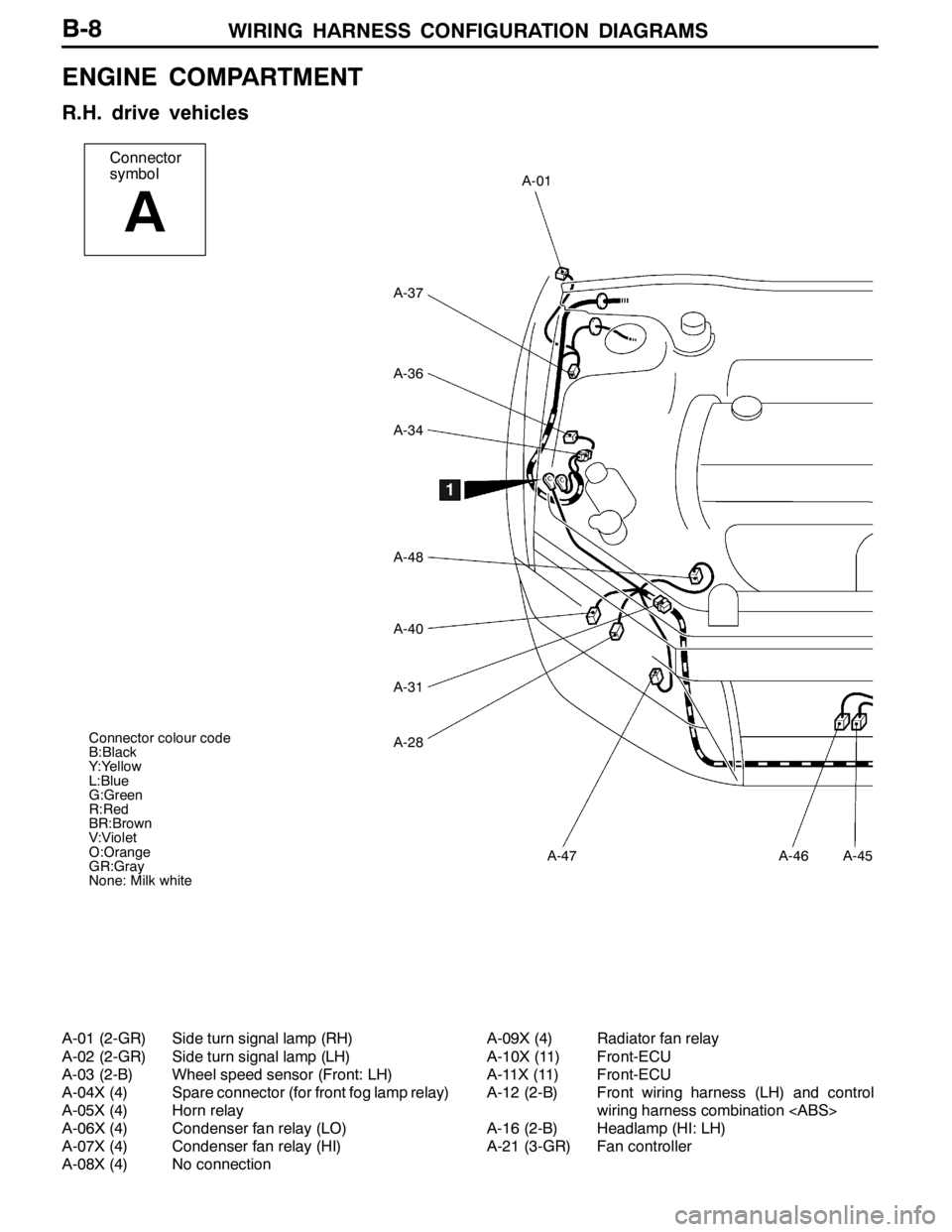
WIRING HARNESS CONFIGURATION DIAGRAMS
Connector
symbol
A
A-01
A-37
A-36
A-34
A-48
A-40
A-31
A-28
A-47A-46A-45
Connector colour code
B:Black
Y:Yellow
L:Blue
G:Green
R:Red
BR:Brown
V:Violet
O:Orange
GR:Gray
None: Milk white
1
B-8
ENGINE COMPARTMENT
R.H. drive vehicles
A-01 (2-GR) Side turn signal lamp (RH)
A-02 (2-GR) Side turn signal lamp (LH)
A-03 (2-B) Wheel speed sensor (Front: LH)
A-04X (4) Spare connector (for front fog lamp relay)
A-05X (4) Horn relay
A-06X (4) Condenser fan relay (LO)
A-07X (4) Condenser fan relay (HI)
A-08X (4) No connectionA-09X (4) Radiator fan relay
A-10X (11) Front-ECU
A-11X (11) Front-ECU
A-12 (2-B) Front wiring harness (LH) and control
wiring harness combination
A-16 (2-B) Headlamp (HI: LH)
A-21 (3-GR) Fan controller
Page 107 of 1449
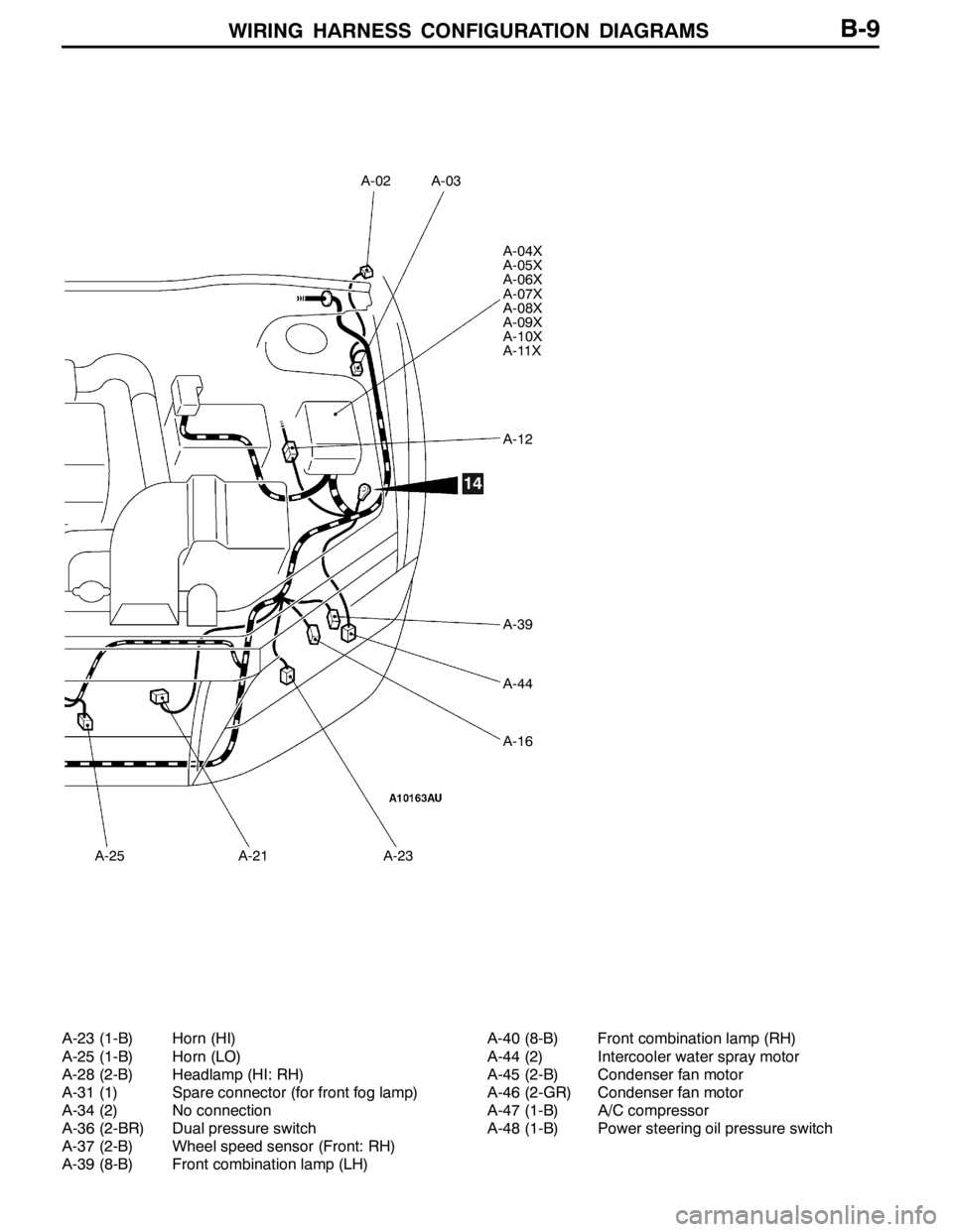
WIRING HARNESS CONFIGURATION DIAGRAMS
A-02
A-25
A-03
A-04X
A-05X
A-06X
A-07X
A-08X
A-09X
A-10X
A-11X
A-12
A-39
A-44
A-16
A-21A-23
14
B-9
A-23 (1-B) Horn (HI)
A-25 (1-B) Horn (LO)
A-28 (2-B) Headlamp (HI: RH)
A-31 (1) Spare connector (for front fog lamp)
A-34 (2) No connection
A-36 (2-BR) Dual pressure switch
A-37 (2-B) Wheel speed sensor (Front: RH)
A-39 (8-B) Front combination lamp (LH)A-40 (8-B) Front combination lamp (RH)
A-44 (2) Intercooler water spray motor
A-45 (2-B) Condenser fan motor
A-46 (2-GR) Condenser fan motor
A-47 (1-B) A/C compressor
A-48 (1-B) Power steering oil pressure switch
Page 108 of 1449
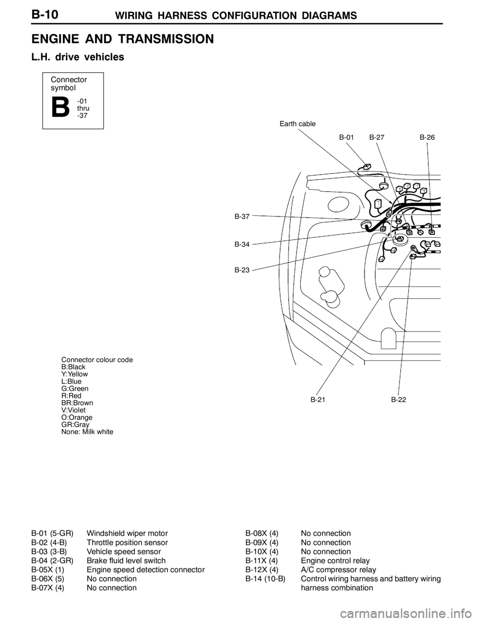
WIRING HARNESS CONFIGURATION DIAGRAMS
Connector
symbol
-01
thru
-37
B
B-37
B-34
B-23
B-01B-27B-26
Earth cable
B-21B-22
Connector colour code
B:Black
Y:Yellow
L:Blue
G:Green
R:Red
BR:Brown
V:Violet
O:Orange
GR:Gray
None: Milk white
B-10
ENGINE AND TRANSMISSION
L.H. drive vehicles
B-01 (5-GR) Windshield wiper motor
B-02 (4-B) Throttle position sensor
B-03 (3-B) Vehicle speed sensor
B-04 (2-GR) Brake fluid level switch
B-05X (1) Engine speed detection connector
B-06X (5) No connection
B-07X (4) No connectionB-08X (4) No connection
B-09X (4) No connection
B-10X (4) No connection
B-11X (4) Engine control relay
B-12X (4) A/C compressor relay
B-14 (10-B) Control wiring harness and battery wiring
harness combination
Page 109 of 1449
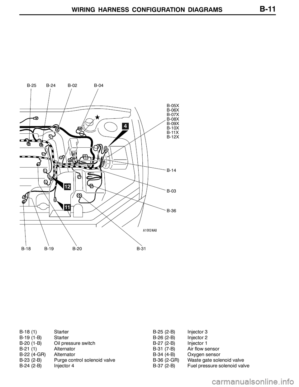
WIRING HARNESS CONFIGURATION DIAGRAMS
B-25
B-18
B-24B-02B-04
B-05X
B-06X
B-07X
B-08X
B-09X
B-10X
B-11X
B-12X
B-14
B-03
B-36
B-19B-20B-31
4
11
12
B-11
B-18 (1) Starter
B-19 (1-B) Starter
B-20 (1-B) Oil pressure switch
B-21 (1) Alternator
B-22 (4-GR) Alternator
B-23 (2-B) Purge control solenoid valve
B-24 (2-B) Injector 4B-25 (2-B) Injector 3
B-26 (2-B) Injector 2
B-27 (2-B) Injector 1
B-31 (7-B) Air flow sensor
B-34 (4-B) Oxygen sensor
B-36 (2-GR) Waste gate solenoid valve
B-37 (2-B) Fuel pressure solenoid valve
Page 110 of 1449
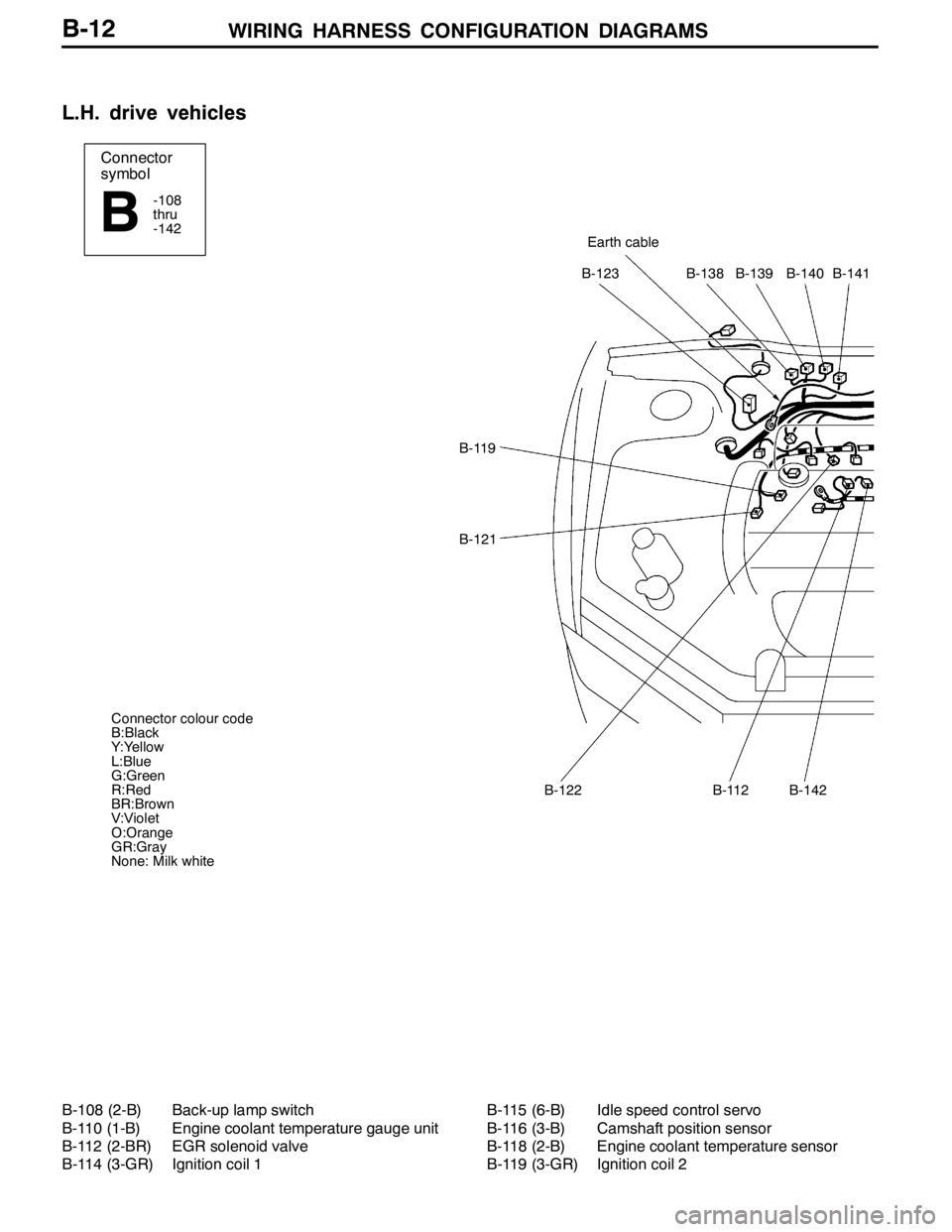
WIRING HARNESS CONFIGURATION DIAGRAMS
Connector
symbol
-108
thru
-142
BEarth cable
B-123B-138B-139B-140B-141
B-119
B-121
B-122B-112B-142
Connector colour code
B:Black
Y:Yellow
L:Blue
G:Green
R:Red
BR:Brown
V:Violet
O:Orange
GR:Gray
None: Milk white
B-12
L.H. drive vehicles
B-108 (2-B) Back-up lamp switch
B-110 (1-B) Engine coolant temperature gauge unit
B-112 (2-BR) EGR solenoid valve
B-114 (3-GR) Ignition coil 1B-115 (6-B) Idle speed control servo
B-116 (3-B) Camshaft position sensor
B-118 (2-B) Engine coolant temperature sensor
B-119 (3-GR) Ignition coil 2