low oil pressure MITSUBISHI LANCER EVOLUTION 2007 Service Owner's Manual
[x] Cancel search | Manufacturer: MITSUBISHI, Model Year: 2007, Model line: LANCER EVOLUTION, Model: MITSUBISHI LANCER EVOLUTION 2007Pages: 1449, PDF Size: 56.82 MB
Page 663 of 1449

MPI -On-vehicle Service13A-131
COMPONENT LOCATION
NameSymbolNameSymbol
A/C relayJFuel pump relay 1, 2Q
A/C switchTFuel pump relay 3H
Air flow sensor (integrated intake air tempera-
ture sensor and barometric pressure sensor)OFuel pump resistorH
Camshaft position sensorNIdle speed control servo (stepper motor)G
Crank angle sensorKIgnition coil (integrated power transister)M
Detonation sensorEInjectorC
Diagnosis connectorSOxygen sensor (front)L
EGR control solenoid valveDOxygen sensor (rear)X
Engine control relayIPower steering fluid pressure switchA
Engine coolant temperature sensorNResistor (for injector)H
Engine warning lamp (check engine lamp)RSecondary air control solenoid valveD
Engine-ECUUThrottle position sensorG
Fan motor relayJVehicle speed sensorF
Fuel pressure control solenoid valveBWaste gate solenoid valveP
ABCDEFGHIJK
LMNOP
QRSTU
Page 709 of 1449
INTAKE AND EXHAUST -Service Specifications/Special Tool/On-vehicle Service15-3
SERVICE SPECIFICATIONS
ItemStandard valueLimit
Turbocharger supercharging pressure (waste gate solenoid
valve not operating) kPa59 - 84-
Initial activation pressure of waste gate actuator (at the stroke
of approximately 1 mm) kPaApproximately 100-
Waste gate solenoid valve coil resistance (at 20_C)Ω29 - 35-
Initial activation pressure of air bypass valve kPaApproximately 53-
Secondary air control solenoid valve coil resistance
(at 20_C)Ω29 - 35-
Manifold distortion of the installation surface mm0.15 or less0.20
SPECIAL TOOL
ToolNumberNameUse
MD998770Oxygen sensor wrenchRemoval and installation of oxygen sensor
ON-VEHICLE SERVICE
TURBOCHARGER SUPERCHARGING
PRESSURE CHECK
Caution
Two persons should be in the vehicle when the test is
conducted; the person in the passenger seat should read
the indications shown by the pressure meter.
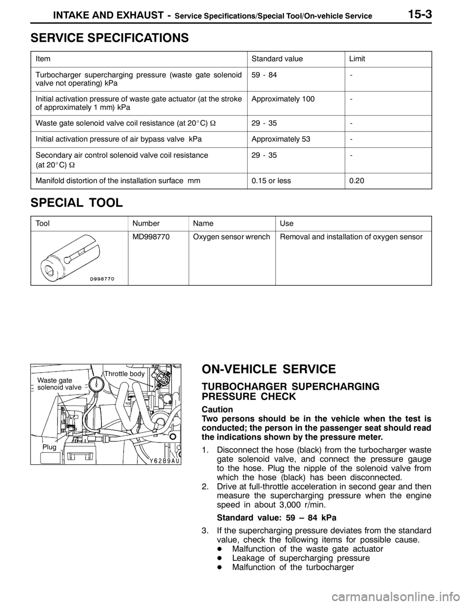
1. Disconnect the hose (black) from the turbocharger waste
gate solenoid valve, and connect the pressure gauge
to the hose. Plug the nipple of the solenoid valve from
which the hose (black) has been disconnected.
2. Drive at full-throttle acceleration in second gear and then
measure the supercharging pressure when the engine
speed in about 3,000 r/min.
Standard value: 59 – 84 kPa
3. If the supercharging pressure deviates from the standard
value, check the following items for possible cause.
DMalfunction of the waste gate actuator
DLeakage of supercharging pressure
DMalfunction of the turbocharger
Throttle bodyWaste gate
solenoid valve
Plug
Page 713 of 1449

INTAKE AND EXHAUST -On-vehicle Service15-7
COIL RESISTANCE CHECK
Measure the resistance between the solenoid valve terminals.
Standard value: 29 – 35Ω(at 20_C)
SECONDARY AIR VALVE CHECK
1. Disconnect the secondary air valve.
2. Connect the hand vacuum pump to the secondary air
valve’s nipple.
3. Apply a negative pressure of 67 kPa, and confirm that
the negative pressure is maintained.
4. Blow in air from the (A) side and (B) side of the secondary
air valve, and inspect the ventilation.
Negative pressureAir blow-in
directionAir ventilation
0 kPa
(State without
negative pressure)(A)→(B)Not ventilated
40 kPa or more(A)→(B)Ventilated
(B)→(A)Not ventilated
VACUUM TANK CHECK
1. Connect the hand vacuum pump to the vacuum tank’s
A nipple. Apply a negative pressure of 67 kPa, and confirm
that the negative pressure is maintained.
2. Connect the hand vacuum pump to the vacuum tank’s
B nipple.
3. Plug the A nipple with a finger, and apply a negative
pressure of 67 kPa. Confirm that the negative pressure
leaks immediately when the finger is released.
BA
A
B
Page 724 of 1449

INTAKE AND EXHAUST -Intake Manifold15-18
INSTALLATION SERVICE POINTS
"AAFUEL HIGH-PRESSURE HOSE CONNECTION
1. Apply a drop of new engine oil to the O-ring.
Caution
Be sure not to let engine oil enter the delivery pipe.
2. While turning the injector, high-pressure fuel hose and
fuel pressure regulator to the right and left, install the
delivery pipe, while being careful not to damage the O-ring.
After installing, check that the hose turns smoothly.
3. If it does not turn smoothly, the O-ring may be trapped,
remove the injector, high-pressure fuel hose or fuel
pressure regulator and then re-insert it into the delivery
pipe and check once again.
4. Tighten the high-pressure fuel hose to the specified torque.
Tightening torque: 5.0±1.0 N⋅m
INSPECTION
Check the following points; replace the part if a problem is
found.
INTAKE MANIFOLD CHECK
1. Check for damage or cracking of any part.
2. Check for obstruction of the negative pressure (vacuum)
outlet port, and for obstruction of the water passage or
gas passage.
3. Using a straight edge and thickness gauge, check for
distortion of the cylinder head installation surface.
Standard value: 0.15 mm
Limit: 0.20 mm
Page 758 of 1449

ENGINE ELECTRICAL -Ignition System16-26
IGNITION SYSTEM
GENERAL INFORMATION
This system is equipped with two ignition coils (A
and B) with built-in power transistors for the No.
1 and No. 4 cylinders and the No. 2 and No. 3
cylinders respectively.
Interruption of the primary current flowing in the
primary side of ignition coil A generates a high
voltage in the secondary side of ignition coil A.
The high voltage thus generated is applied to the
spark plugs of No. 1 and No. 4 cylinders to generate
sparks. At the time that the sparks are generated
at both spark plugs, if one cylinder is at the
compression stroke, the other cylinder is at the
exhaust stroke, so that ignition of the compressed
air/fuel mixture occurs only for the cylinder which
is at the compression stroke.
In the same way, when the primary current flowing
in ignition coil B is interrupted, the high voltage
thus generated is applied to the spark plugs of
No. 2 and No. 3 cylinders.
The Engine-ECU turns the two power transistors
inside the ignition coils alternately on and off. Thiscauses the primary currents in the ignition coils
to be alternately interrupted and allowed to flow
to fire the cylinders in the order 1-3-4-2.
The Engine-ECU determines which ignition coil
should be controlled by means of the signals from
the camshaft position sensor which is incorporated
in the camshaft and from the crank angle sensor
which is incorporated in the crankshaft. It also
detects the crankshaft position in order to provide
ignition at the most appropriate timing in response
to the engine operation conditions. It also detects
the crankshaft position in order to provide ignition
at the most appropriate timing in response to the
engine operation conditions.
When the engine is cold or operated at high
altitudes, the ignition timing is slightly advanced
to provide optimum performance.
When the automatic transmission shifts gears, the
ignition timing is also retarded in order to reduce
output torque, thereby alleviating shifting shocks.
SYSTEM DIAGRAM
Barometric pressure sensor
Intake air temperature sensor
Engine coolant temperature sensor
Camshaft position sensor
Crank angle sensor
Ignition switch - ST
Vehicle speed signalEngine-ECU
Ignition coil A
Ignition coil B Ignition switch
Spark plugBattery
To tachometerCylinder No. Air flow sensor
1 4
23
Detonation sensor
Page 810 of 1449

22A-2
MANUAL
TRANSMISSION
CONTENTS
GENERAL 3.................................
Outline of Changes 3...........................
GENERAL INFORMATION 3..................
SERVICE SPECIFICATION 3..................
LUBRICANTS 3..............................
SPECIAL TOOLS 4...........................
TROUBLESHOOTING
ON-VEHICLE SERVICE 40....................
Transmission Oil Check 40......................
Transmission Oil Replacement 40................
Transfer Oil Check 40..........................
Transfer Oil Replacement 40....................
Fluid Check
Bleeding
Hydraulic Pressure Check
Wheel Speed Sensor Output Voltage
Measurement
TRANSMISSION CONTROL* 46...............
TRANSFER ASSEMBLY 49...................
TRANSMISSION ASSEMBLY 52...............
4WD-ECU
SENSOR, SWITCH AND RELAY
AYC> 56.....................................
HYDRAULIC UNIT Refer to GROUP27B.......
WARNING REGARDING SERVICING OF SUPPLEMENTAL RESTRAINT SYSTEM (SRS) EQUIPPED VEHICLES
WARNING!
(1) Improper service or maintenance of any component of the SRS, or any SRS-related component, can lead to personal
injury or death to service personnel (from inadvertent firing of the air bag) or to driver and passenger (from rendering
the SRS inoperative).
(2) Service or maintenance of any SRS component or SRS-related component must be performed only at an authorized
MITSUBISHI dealer.
(3) MITSUBISHI dealer personnel must thoroughly review this manual, and especially its GROUP 52B - Supplemental
Restraint System (SRS) before beginning any service or maintenance of any component of the SRS or any SRS-related
component.
NOTE
The SRS includes the following components: SRS-ECU, SRS warning lamp, air bag module, clock spring, and interconnecting
wiring. Other SRS-related components (that may have to be removed/installed in connection with SRS service or maintenance) are
indicated in the table of contents by an asterisk (*).
Page 811 of 1449

MANUAL TRANSMISSION -General/General Information/
Service Specification/Lubricants22A-3
GENERAL
OUTLINE OF CHANGE
With the addition of the EVOLUTION-VII, the W5M51 transmission service adjustment procedure has
been set as follows.
GENERAL INFORMATION
ItemsSpecifications
GradeRS, RS IIRS, RS II (With super cross gear)
Transmission modelW5M51
Engine model4G63-DOHC-T/C
Type5-speed, floor-shift
Gear ratio1st2.7852.785
2nd1.9501.950
3rd1.4071.444
4th1.0311.096
5th0.7200.825
Reverse3.4163.416
Final reduction ratio
(Differential gear ratio)4.5294.529
Front limited-slip differential
(Helical-gear type)Not providedProvided
TransferReduction ratio3.3073.307
Limited-slipdifferentialVCU or hydraulic multi plate
clutch (ACD)VCU or hydraulic multi plate
clutch (ACD)
SERVICE SPECIFICATION
ItemStandard value
Hydraulic unit generation oil pressureMPa1.0 - 1.6
LUBRICANTS
ItemSpecified lubricantQuantity L
Transmission oilGear oil SAE 75W-90 or 75W-85W conforming to API GL-42.8
Transfer
oilVehicles without ACD or ve-
hicles without ACD and AYCMITSUBISHI Genuine Gear Oil Part No.8149630 EX,
CASTROL HYPOY LS (GL-5, SAE 90), SHELL-LSD
(GL 5SAE80W90)orequivalent
0.55
Vehicles with ACD or vehicles
with ACD and AYC(GL-5, SAE 80W - 90) or equivalent0.6
FluidPiping between ACD and
hydraulic unitDIA QUEEN ATF SP III0.9
Pipes between ACD and hy-
draulic unit and between AYC
and hydraulic unit1.0
Page 812 of 1449

MANUAL TRANSMISSION - Special Tools22A-4
SPECIAL TOOLS
ToolNumberNameUse
MB991502MUT-IISub as-
semblyDiagnosis code checking
MB991529Diagnosis code
checking harness
MB991348Test harness setGsensor check
MD998330
(including
MD998331)Oil pressure gauge
(3.0 MPa)Hydraulic pressure measurement
MB991705Adapter
MB990635,
MB991113 or
MB991406
Steering linkage
pullerTie rod end and lower disconnection
GENERAL
SERVICE
TOOL
MZ203827Engine lifterSupporting the engine assembly during
removal and installation of the transmission
MB991453Engine hangerat-
tachment set
MB991721Slide hammerOutput shaft removal
Page 842 of 1449
MANUAL TRANSMISSION - Troubleshooting
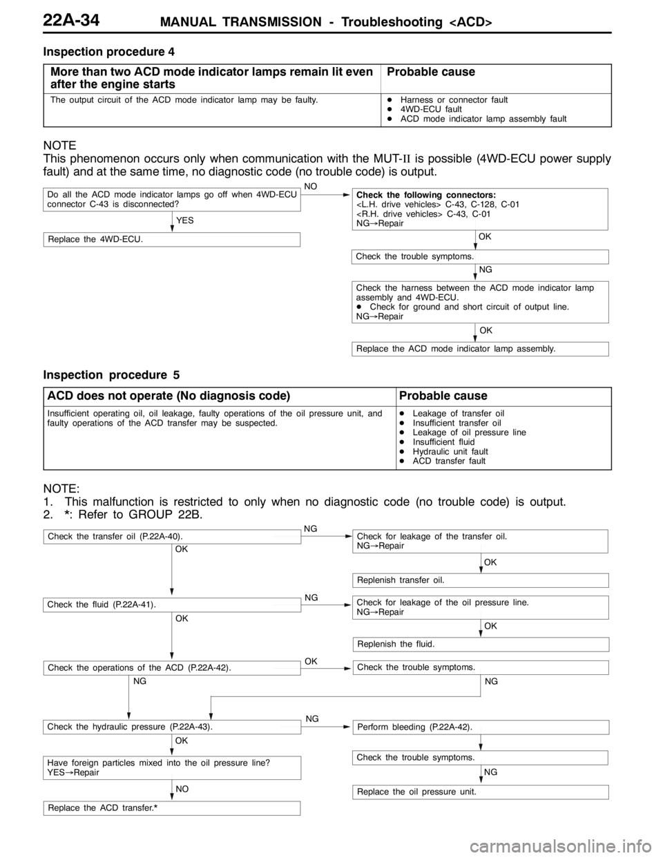
Inspection procedure 4
More than two ACD mode indicator lamps remain lit even
after the engine starts
Probable cause
The output circuit of the ACD mode indicator lamp may be faulty.DHarness or connector fault
D4WD-ECU fault
DACD mode indicator lamp assembly fault
NOTE
This phenomenon occurs only when communication with the MUT-IIis possible (4WD-ECU power supply
fault) and at the same time, no diagnostic code (no trouble code) is output.
NO
Replace the 4WD-ECU.
Do all the ACD mode indicator lamps go off when 4WD-ECU
connector C-43 is disconnected?
YES
Replace the ACD mode indicator lamp assembly.OK
NG
Check the trouble symptoms.
Check the following connectors:
NG→Repair
OK
Check the harness between the ACD mode indicator lamp
assembly and 4WD-ECU.
DCheck for ground and short circuit of output line.
NG→Repair
Inspection procedure 5
ACD does not operate (No diagnosis code)
Probable cause
Insufficient operating oil, oil leakage, faulty operations of the oil pressure unit, and
faulty operations of the ACD transfer may be suspected.DLeakage of transfer oil
DInsufficient transfer oil
DLeakage of oil pressure line
DInsufficient fluid
DHydraulic unit fault
DACD transfer fault
NOTE:
1. This malfunction is restricted to only when no diagnostic code (no trouble code) is output.
2. *: Refer to GROUP 22B.
OK
NG OKNG OKNG
NG
NO
NG
OK
Replenish transfer oil.
Replace the oil pressure unit.
Have foreign particles mixed into the oil pressure line?
YES→Repair
Check the hydraulic pressure (P.22A-43).Perform bleeding (P.22A-42).
Check the fluid (P.22A-41).Check for leakage of the oil pressure line.
NG→Repair
Check the transfer oil (P.22A-40).Check for leakage of the transfer oil.
NG→Repair
Check the trouble symptoms.
Replace the ACD transfer.*OK
Replenish the fluid.
OK
NG
Check the operations of the ACD (P.22A-42).Check the trouble symptoms.
Page 844 of 1449

MANUAL TRANSMISSION - Troubleshooting
Item
no.Normal conditions Check condition Check item
19Pressure sensor power
supplyIgnition switch: ONApprox.5 V
20Valve power supplyIgnition switch: ONSystem voltage
21Steering wheel sensor
voltage
are displayed alter-
nately.
22Steering wheel sensor
voltage
are displayed alter-
nately.
23Steering wheel sensor
ltSTN
Ignition switch: ONSteering wheel: Neutral1-2Vg
voltage
g
Steering wheel: Turn2.5 - 4.5 V
51Idle switchIgnition switch: ONAccelerator pedal: Full
closedON
Accelerator pedal: PressOFF
52Steering wheel sensor
STN
Ignition switch: ONsteering wheel: NeutralONg
g
Steering wheel: Turn from
the neutral positionOFF
53Steering wheel sensor
played alternaltely.
54Steering wheel sensor
played alternately
55Steering wheel sensor
learning
tral position learning exe-
cutedON
Steering wheel sensor neu-
tral position learning unex-
ecutedOFF
56Stop lamp switchIgnition switch: ONBrake pedal: DepressONppg
Engine: StoppedBrake pedal: ReleaseOFF
57Motor monitorElectric pump motor is currently operatingON
Electric pump motor is currently not operatingOFF
58Oil pressure stateElectric pump motor is currently operatingLOWp
Electric pump motor is currently not operatingHIGH
59Directional valve
Ri ht
AYC clutch right side is currently operatingON
60Directional valve
Lft
AYC clutch left side is currently operatingON
61ABS monitorABS is currently operatingON
ABS is currently not operatingOFF
62Parking brake switchIgnition switch: ONParking brake lever: PullONgg
Engine:StoppedParking brake lever: Re-
leaseOFF
63ACD mode switchIgnition switch: ONACD mode switch: PressONg
Engine:StoppedACD mode switch: ReleaseOFF