Serpentine MITSUBISHI LANCER EVOLUTION 2007 Service Repair Manual
[x] Cancel search | Manufacturer: MITSUBISHI, Model Year: 2007, Model line: LANCER EVOLUTION, Model: MITSUBISHI LANCER EVOLUTION 2007Pages: 1449, PDF Size: 56.82 MB
Page 422 of 1449

ENGINE -Crankshaft Pulley/Camshaft and Camshaft Oil Seal11A-16
REMOVAL SERVICE POINT
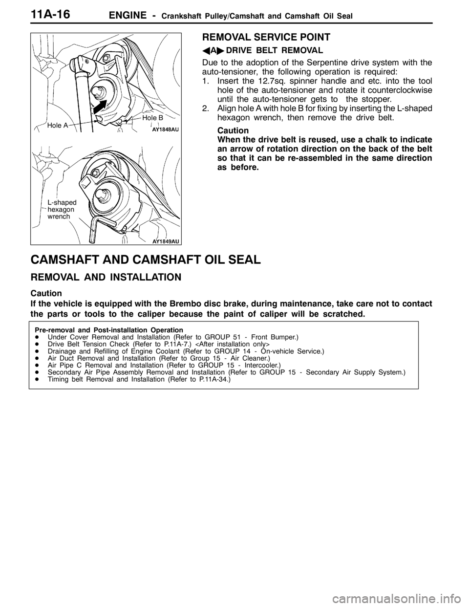
AA"DRIVE BELT REMOVAL
Due to the adoption of the Serpentine drive system with the
auto-tensioner, the following operation is required:
1. Insert the 12.7sq. spinner handle and etc. into the tool
hole of the auto-tensioner and rotate it counterclockwise
until the auto-tensioner gets to the stopper.
2. Align hole A with hole B for fixing by inserting the L-shaped
hexagon wrench, then remove the drive belt.
Caution
When the drive belt is reused, use a chalk to indicate
an arrow of rotation direction on the back of the belt
so that it can be re-assembled in the same direction
as before.
CAMSHAFT AND CAMSHAFT OIL SEAL
REMOVAL AND INSTALLATION
Caution
If the vehicle is equipped with the Brembo disc brake, during maintenance, take care not to contact
the parts or tools to the caliper because the paint of caliper will be scratched.
Pre-removal and Post-installation Operation
DUnder Cover Removal and Installation (Refer to GROUP 51 - Front Bumper.)
DDrive Belt Tension Check (Refer to P.11A-7.)
DDrainage and Refilling of Engine Coolant (Refer to GROUP 14 - On-vehicle Service.)
DAir Duct Removal and Installation (Refer to Group 15 - Air Cleaner.)
DAir Pipe C Removal and Installation (Refer to GROUP 15 - Intercooler.)
DSecondary Air Pipe Assembly Removal and Installation (Refer to GROUP 15 - Secondary Air Supply System.)
DTiming belt Removal and Installation (Refer to P.11A-34.)
Hole A
L-shaped
hexagon
wrench
Hole B
Page 452 of 1449

ENGINE -Engine Assembly11A-46
REMOVAL SERVICE POINTS
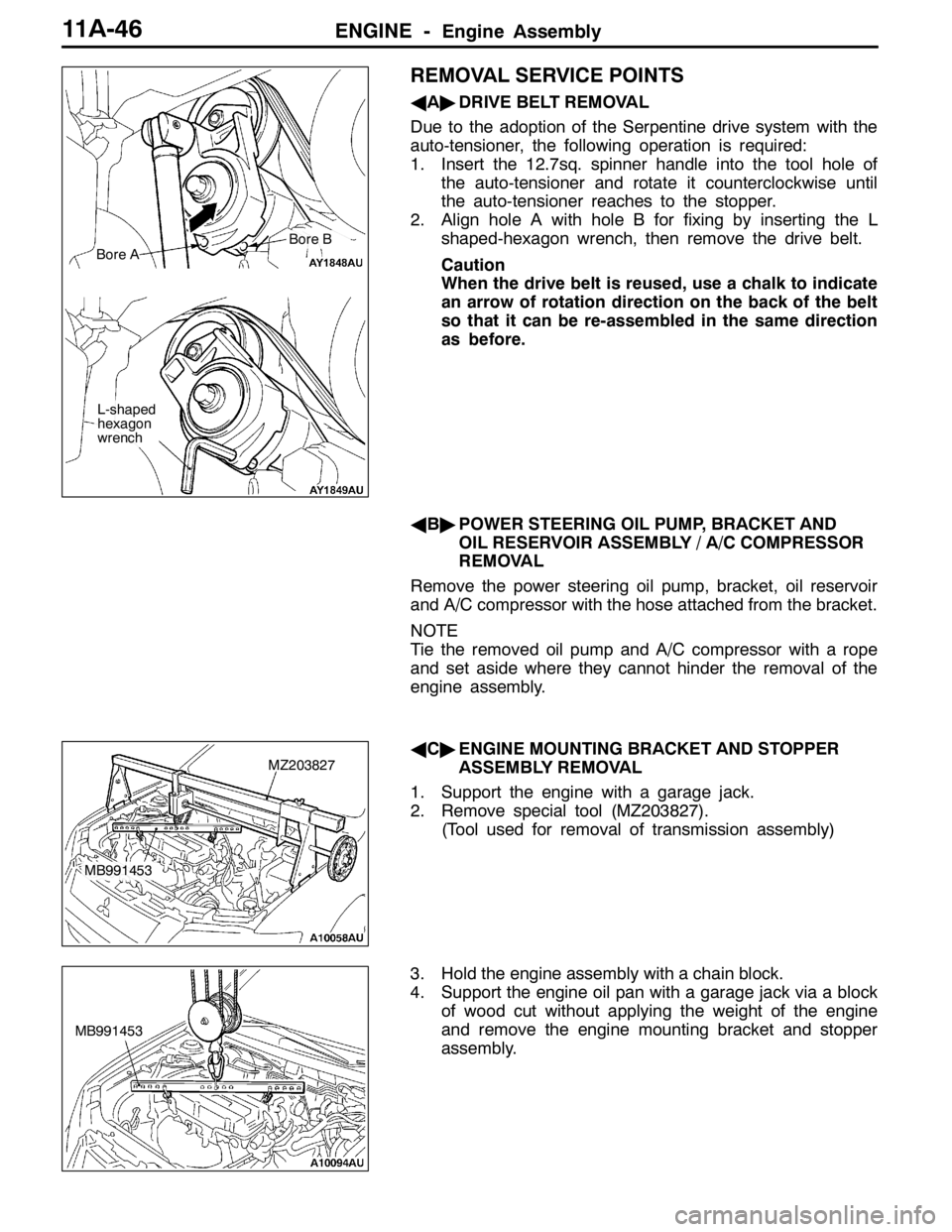
AA"DRIVE BELT REMOVAL
Due to the adoption of the Serpentine drive system with the
auto-tensioner, the following operation is required:
1. Insert the 12.7sq. spinner handle into the tool hole of
the auto-tensioner and rotate it counterclockwise until
the auto-tensioner reaches to the stopper.
2. Align hole A with hole B for fixing by inserting the L
shaped-hexagon wrench, then remove the drive belt.
Caution
When the drive belt is reused, use a chalk to indicate
an arrow of rotation direction on the back of the belt
so that it can be re-assembled in the same direction
as before.
AB"POWER STEERING OIL PUMP, BRACKET AND
OIL RESERVOIR ASSEMBLY / A/C COMPRESSOR
REMOVAL
Remove the power steering oil pump, bracket, oil reservoir
and A/C compressor with the hose attached from the bracket.
NOTE
Tie the removed oil pump and A/C compressor with a rope
and set aside where they cannot hinder the removal of the
engine assembly.
AC"ENGINE MOUNTING BRACKET AND STOPPER
ASSEMBLY REMOVAL
1. Support the engine with a garage jack.
2. Remove special tool (MZ203827).
(Tool used for removal of transmission assembly)
3. Hold the engine assembly with a chain block.
4. Support the engine oil pan with a garage jack via a block
of wood cut without applying the weight of the engine
and remove the engine mounting bracket and stopper
assembly.
Bore A
L-shaped
hexagon
wrench
Bore B
MZ203827
MB991453
MB991453
Page 744 of 1449

ENGINE ELECTRICAL -Charging System16-12
REMOVAL SERVICE POINTS
AA"DELIVERY PIPE, INJECTOR, AND FUEL
PRESSURE REGULATOR ASSEMBLY REMOVAL
After loosening the installed parts, set the related parts
aside to make some space for removing the alternator.
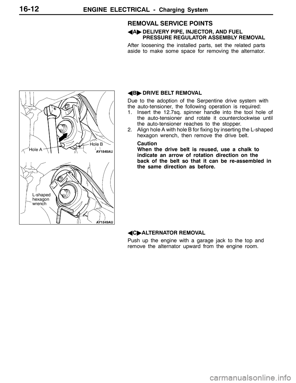
AB"DRIVE BELT REMOVAL
Due to the adoption of the Serpentine drive system with
the auto-tensioner, the following operation is required:
1. Insert the 12.7sq. spinner handle into the tool hole of
the auto-tensioner and rotate it counterclockwise until
the auto-tensioner reaches to the stopper.
2. Align hole A with hole B for fixing by inserting the L-shaped
hexagon wrench, then remove the drive belt.
Caution
When the drive belt is reused, use a chalk to
indicate an arrow of rotation direction on the
back of the belt so that it can be re-assembled in
the same direction as before.
AC"ALTERNATOR REMOVAL
Push up the engine with a garage jack to the top and
remove the alternator upward from the engine room.
Hole A
L-shaped
hexagon
wrench
Hole B
Page 1439 of 1449

HEATER, AIR CONDITIONER AND VENTILATION-Compressor55-37
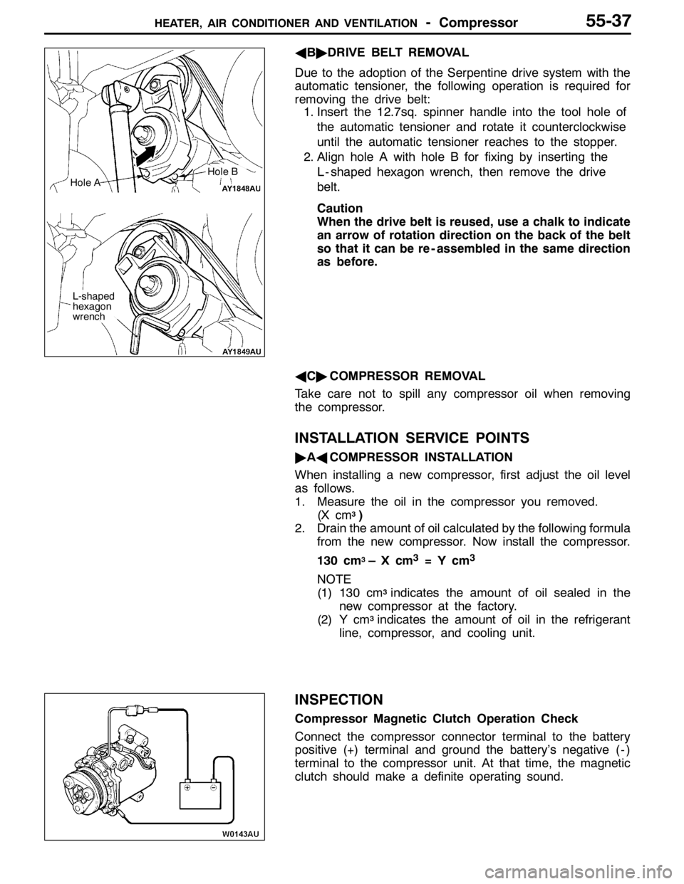
AB"DRIVE BELT REMOVAL
Due to the adoption of the Serpentine drive system with the
automatic tensioner, the following operation is required for
removing the drive belt:
1. Insert the 12.7sq. spinner handle into the tool hole of
the automatic tensioner and rotate it counterclockwise
until the automatic tensioner reaches to the stopper.
2. Align hole A with hole B for fixing by inserting the
L - shaped hexagon wrench, then remove the drive
belt.
Caution
When the drive belt is reused, use a chalk to indicate
an arrow of rotation direction on the back of the belt
so that it can be re - assembled in the same direction
as before.
AC"COMPRESSOR REMOVAL
Take care not to spill any compressor oil when removing
the compressor.
INSTALLATION SERVICE POINTS
"AACOMPRESSOR INSTALLATION
When installing a new compressor, first adjust the oil level
as follows.
1. Measure the oil in the compressor you removed.
(X cm
3)
2. Drain the amount of oil calculated by the following formula
from the new compressor. Now install the compressor.
130 cm
3–Xcm3=Ycm3
NOTE
(1) 130 cm3indicates the amount of oil sealed in the
new compressor at the factory.
(2) Y cm
3indicates the amount of oil in the refrigerant
line, compressor, and cooling unit.
INSPECTION
Compressor Magnetic Clutch Operation Check
Connect the compressor connector terminal to the battery
positive (+) terminal and ground the battery’s negative ( - )
terminal to the compressor unit. At that time, the magnetic
clutch should make a definite operating sound.
Hole A
L-shaped
hexagon
wrench
Hole B