engine MITSUBISHI LANCER EVOLUTION 2007 Service Repair Manual
[x] Cancel search | Manufacturer: MITSUBISHI, Model Year: 2007, Model line: LANCER EVOLUTION, Model: MITSUBISHI LANCER EVOLUTION 2007Pages: 1449, PDF Size: 56.82 MB
Page 1 of 1449
00
11
12
13
14
15
16
17
21
22
25
26
27
31
32
33
34
35
36
37
42
51
52
54
55
General........................
Engine .........................
Engine Lubrication .............
Fuel ...........................
Engine Cooling .................
Intake and Exhaust ............
Engine Electrical ...............
Engine and Emission Control ....
Clutch .........................
Manual Transmission ...........
Propeller Shaft .................
Front Axle ......................
Rear Axle ......................
Wheel and Tyre .................
Power Plant Mount ..............
Front Suspension ...............
Rear Suspension ...............
Service Brakes .................
Parking Brakes .................
Steering ........................
Body ...........................
Exterior ........................
Chassis Electrical ..............
Electrical Wiring ................
Body Repair ....................
WORKSHOP
MANUAL
FOREWORD
This Workshop Manual contains procedures for
service mechanics, including removal, disassembly,
inspection, adjustment, reassembly and
installation. Use the following manuals in
combination with this manual as required.
TECHNICAL INFORMATION MANUAL N0104CT9A
All information, illustrations and product
descriptions contained in this manual are current
as at the time of publication. We, however, reserve
the right to make changes at any time without prior
notice or obligation.
The EVOLUTION-VII is sold exclusively through
RALLIART Inc. Since the EVOLUTION-VII is a
rally-based model, it will not be warranted and will
not be homologated for general production.
Therefore, any service matters on the
EVOLUTION-VII should be inquired to RALLIART
Inc. as usual.
EMitsubishi Motors Corporation May 2001
Interior and Supplemental
Restraint System (SRS) ........
Heater, Air Conditioner and
Ventilation .....................
Page 5 of 1449

BODY CONSTRUCTION -Body ComponentsA-3
1. Headlamp support panel
2. Hood lock stay
3. Front end crossmember
4. Front end upper bar
5. Headlamp support panel side
6. Front fender shield
7. Front upper frame inner
8. Upper frame bulkhead front
9. Upper frame bulkhead
10. Upper frame bulkhead rear
11. Front sidemember inner
12. Engine mount bracket
13. Front sidemember rear
14. Front sidemember outer
15. Spring house panel
16. Dash panel
17. Dash panel silencer
18. Dash panel reinforcement
19. Upper frame to front pillar brace
20. Upper frame extension outer
21. Upper frame extension inner
22. Cowl top lower panel
23. Cowl top inner panel
24. Cowl top upper panel
25. Front deck crossmember
26. Hood inner panel
27. Hood outer panel
28. Front roof rail
29. Front roof bow
30. Roof panel
31. Rear roof bow
32. Rear roof rail
33. Seat back plate
34. Rear seat back panel
35. Rear shelf panel
36. Rear seat back brace
37. Trunk lid outer panel
38. Trunk lid inner panel
39. Trunk lid hinge
40. Quarter inner extension rear
41. Quarter corner panel42. Rear combination lamp housing
43. Side roof rail inner
44. Front pillar inner upper
45. Front pillar inner lower
46. Center pillar inner
47. Side outer panel
48. Rear wheel house inner panel
49. Quarter inner panel
50. Rear floor side brace
51. Quarter outer extension lower
52. Fuel filler door
53. Rear license plate bracket
54. Rear end panel outer
55. Rear end panel inner
56. Rear door outer panel
57. Rear door side door beam
58. Rear door inner panel
59. Front door outer panel
60. Front door side door beam
61. Front door inner panel
62. Fender panel
63. Front floor crossmember rear
64. Front floor crossmember front
65. Front floor side sill inner
66. Front floor sidemember
67. Backbone reinforcement
68. Installment panel center bracket reinforcement
69. Front floor pan
70. Front floor extension panel rear
71. Rear floor extension
72. Rear floor pan
73. Seat back plate extension
74. Jack bracket
75. Spare tire bracket
76. Towing hook reinforcement
77. Rear floor sidemember extension
78. Crossmember center support
79. Rear floor crossmember
80. Rear floor sidemember
81. Rear seat back reinforcement
Page 11 of 1449
BODY CONSTRUCTION -Body Construction CharacteristicsA-9
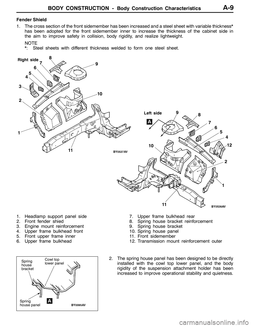
Fender Shield
1. The cross section of the front sidemember has been increased and a steel sheet with variable thickness*
has been adopted for the front sidemember inner to increase the thickness of the cabinet side in
the aim to improve safety in collision, body rigidity, and realize lightweight.
NOTE
*: Steel sheets with different thickness welded to form one steel sheet.
12 345678
9
1112
Right side
Left side
10
10
124 5 6 7 8 9
A
11
1. Headlamp support panel side
2. Front fender shied
3. Engine mount reinforcement
4. Upper frame bulkhead front
5. Front upper frame inner
6. Upper frame bulkhead7. Upper frame bulkhead rear
8. Spring house bracket reinforcement
9. Spring house bracket
10. Spring house panel
11. Front sidemember
12. Transmission mount reinforcement outer
2. The spring house panel has been designed to be directly
installed with the cowl top lower panel, and the body
rigidity of the suspension attachment holder has been
increased to improve operational stability and quietness.
Spring
house
bracket
Spring
house panelA
Cowl top
lower panel
Page 12 of 1449
BODY CONSTRUCTION -Body Construction Characteristics
A
1 2 3B
5
1
3
A-10
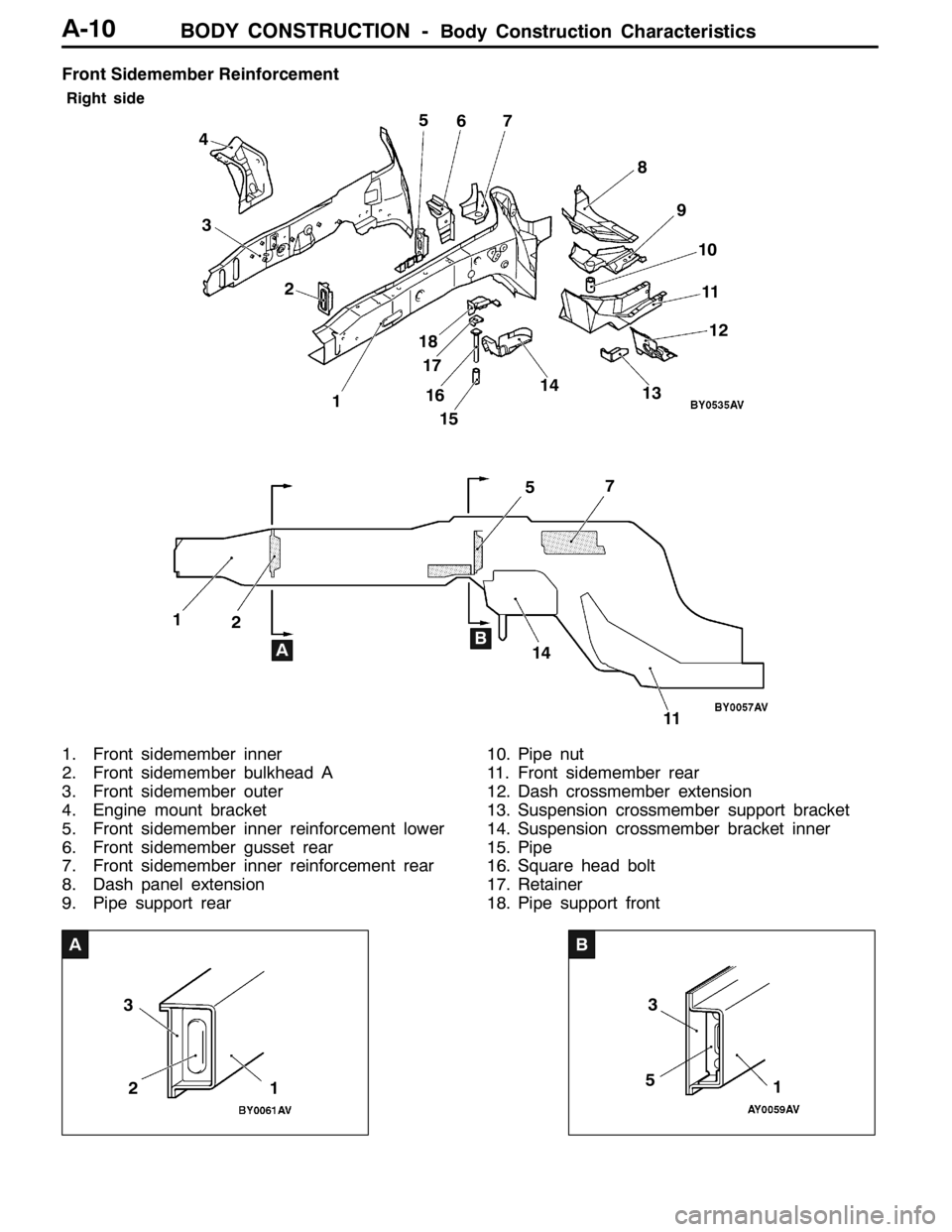
Front Sidemember Reinforcement
Right side
57 2 3 45
67
8
9
10
11
AB 11512
11 14
1413
16 17 18
1
2
1. Front sidemember inner
2. Front sidemember bulkhead A
3. Front sidemember outer
4. Engine mount bracket
5. Front sidemember inner reinforcement lower
6. Front sidemember gusset rear
7. Front sidemember inner reinforcement rear
8. Dash panel extension
9. Pipe support rear10. Pipe nut
11. Front sidemember rear
12. Dash crossmember extension
13. Suspension crossmember support bracket
14. Suspension crossmember bracket inner
15. Pipe
16. Square head bolt
17. Retainer
18. Pipe support front
Page 14 of 1449

BODY CONSTRUCTION -Body Construction CharacteristicsBODY CONSTRUCTION -Body Construction CharacteristicsA-12
Front Deck
Strut house gussetandupper frame to front pillar brace have been added to improve body rigidity.
7
1 24 56
8
9
310
11
12 13
14
15
16
1. Strut tower bar bracket
2. Cowl top lower panel
3. Cowl top upper bracket center
4. Cowl top upper reinforcement center
5. Cowl top upper bracket side (LHD)
6. Cowl top inner panel
7. Cowl top upper panel
8. Pedal support bracket9. Clutch pedal support bracket
10. A/C Unit bracket (RHD)
11. Upper frame extension outer
12. Upper frame to front pillar brace
13. Cowl top upper reinforcement
14. Cowl top lower bracket
15. Upper frame extension inner
16. Strut house gusset
Dash Panel
1. A dash panel crossmember has been added and the thickness of the dash panel lower has been
increased to improve collision stability.
2. A silencer (steel sheet binding type vibration damping material) has been added between the dash
panel and dash panel silencer to control the penetrating sound and vibration from the engine.
18 3
76 5 4
2
1. Dash panel crossmember
2. Dash panel
3. Dash silencer center
4. Dash panel silencer5. Accel pedal reinforcement (LHD)
6. Dash panel reinforcement
7. Dash lower reinforcement (LHD)
8. Dash panel lower
Page 82 of 1449
BODY COLOUR -Body Colour Code/Body Colour ChartsF-2
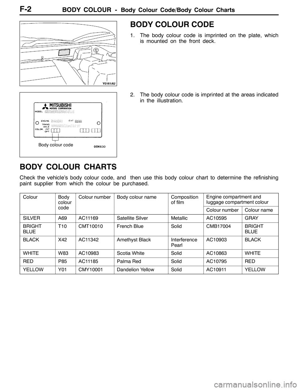
BODY COLOUR CODE
1. The body colour code is imprinted on the plate, which
is mounted on the front deck.
2. The body colour code is imprinted at the areas indicated
in the illustration.
BODY COLOUR CHARTS
Check the vehicle’s body colour code, and then use this body colour chart to determine the refinishing
paint supplier from which the colour be purchased.
ColourBody
colour
d
Colour numberBody colour nameComposition
of filmEngine compartment and
luggage compartment colour
codeColour numberColour name
SILVERA69AC11169Satellite SilverMetallicAC10595GRAY
BRIGHT
BLUET10CMT10010French BlueSolidCMB17004BRIGHT
BLUE
BLACKX42AC11342Amethyst BlackInterference
PearlAC10903BLACK
WHITEW83AC10983Scotia WhiteSolidAC10863WHITE
REDP85AC11185Palma RedSolidAC10795RED
YELLOWY01CMY10001Dandelion YellowSolidAC10911YELLOW
Body colour code
Page 83 of 1449

BODY COLOUR -Body Colour ChartsF-3
NEW COLOUR NUMBERS
123 4 5
C
10 MT
010Example
(Body colour code T10)
No.ItemContent
1Identification codeC: The colour number is indicated.
2Manufacture center codeM: Japan (Automobile Engineering Center)
T: Japan (Truck and Bus Engineering Center)
3System colour codeW (N): White
H (A, U): Silver/Gray
X (J): Black
R (P): Red
Y (C, S, E, M, K): Brown/Yellow (including Orange, Maroon, and Gold)
G (F, L): Green/Olive
B (T, D): Blue
V: Purple
( ) Codes within the parenthesis can be also used.
4Colour classification codeFrom 10 to 16: The body colour is indicated.
17: The body inner panel colour is indicated.
5Specific numberSerial number numbering management
BODY COLOURING
BUMPER
Front bumper
AA 22
1
1 Body colour
2 Material colour
12
1
Page 89 of 1449
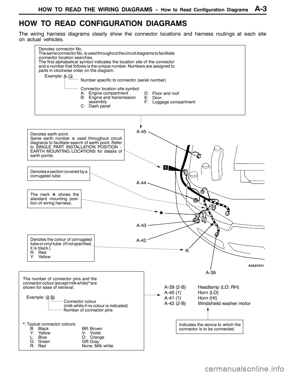
HOW TO READ THE WIRING DIAGRAMS -How to Read Configuration DiagramsA-3
HOW TO READ CONFIGURATION DIAGRAMS
The wiring harness diagrams clearly show the connector locations and harness routings at each site
on actual vehicles.
Denotes connector No.
The same connector No. is used throughout the circuit diagrams to facilitate
connector location searches.
The first alphabetical symbol indicates the location site of the connector
and a number that follows is the unique number. Numbers are assigned to
parts in clockwise order on the diagram.
A-43
Example: A-12
Number specific to connector (serial number)
Connector location site symbol
A: Engine compartment
B: Engine and transmission
assembly
C: Dash panel
Denotes earth point.
Same earth number is used throughout circuit
diagrams to facilitate search of earth point. Refer
to SINGLE PART INSTALLATION POSITION -
EARTH MOUNTING LOCATIONS for details of
earth points.
Indicates the device to which the
connector is to be connected.
A-39 (2-B) Headlamp (LO: RH)
A-40 (1) Horn (LO)
A-41 (1) Horn (HI)
A-42 (2-B) Windshield washer motor
The number of connector pins and the
connector colour (except milk white)* are
shown for ease of retrieval.
Example: (2
-B)
Connector colour
(milk white if no colour is indicated)
Number of connector pins
*: Typical connector colours
B: Black
Y: Yellow
L: Blue
G: Green
R: Red
The markLshows the
standard mounting posi-
tion of wiring harness.
R
A-44
A-45
A-42
A-39
Denotes the colour of corrugated
tube or vinyl tube. (If not specified,
it is black.)
R: Red
Y: Yellow
Denotes a section covered by a
corrugated tube.
BR: Brown
V: Violet
O: Orange
GR: Gray
None: Milk whiteD: Floor and roof
E: Door
F: Luggage compartment
Page 90 of 1449
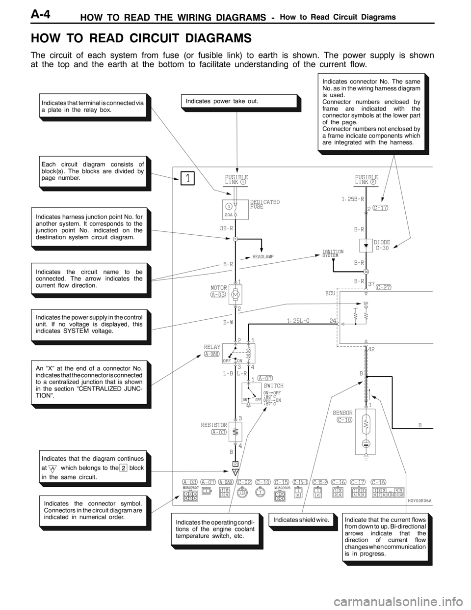
HOW TO READ THE WIRING DIAGRAMS -How to Read Circuit DiagramsA-4
HOW TO READ CIRCUIT DIAGRAMS
The circuit of each system from fuse (or fusible link) to earth is shown. The power supply is shown
at the top and the earth at the bottom to facilitate understanding of the current flow.
Indicates the power supply in the control
unit. If no voltage is displayed, this
indicates SYSTEM voltage.
Indicates power take out.
Indicates connector No. The same
No. as in the wiring harness diagram
is used.
Connector numbers enclosed by
frame are indicated with the
connector symbols at the lower part
of the page.
Connector numbers not enclosed by
a frame indicate components which
are integrated with the harness.
Indicates harness junction point No. for
another system. It corresponds to the
junction point No. indicated on the
destination system circuit diagram.
Indicates the circuit name to be
connected. The arrow indicates the
current flow direction.
An “X” at the end of a connector No.
indicates that the connector is connected
to a centralized junction that is shown
in the section “CENTRALIZED JUNC-
TION”.
Indicates the operating condi-
tions of the engine coolant
temperature switch, etc.
Indicates the connector symbol.
Connectors in the circuit diagram are
indicated in numerical order.
Indicates shield wire.
Indicates that terminal is connected via
a plate in the relay box.
Each circuit diagram consists of
block(s). The blocks are divided by
page number.
Indicates that the diagram continues
at
Awhich belongs to the block
in the same circuit.2
Indicate that the current flows
from down to up. Bi-directional
arrows indicate that the
direction of current flow
changes when communication
is in progress.
Page 96 of 1449

HOW TO READ THE WIRING DIAGRAMS -Abbreviation SymbolsA-10
ABBREVIATION SYMBOLS
The abbreviation symbols used in wiring diagrams are defined below.
1. Abbreviation symbols used for system name
Abbreviation
symbolsMeaningAbbreviation
symbolsMeaning
A/CAir conditionerEGRExhaust gas recirculation
ABSAnti-skid braking systemETACSElectronic time alarm control system
ACDActive center differentialSRSSupplemental restraint system
AY CActive yaw control
2. Abbreviation symbols used for combination meters
Abbreviation
symbolsMeaningAbbreviation
symbolsMeaning
ABSAnti-skid braking system warning lampSNOWActive center differential mode indicator
lamp
BEAMHigh beam indicator lampSPEEDSpeedmeter
BRAKEBrake warning lampSRSSupplemental restraint system warning
lamp
CHECK
ENGINECheck engine warning lampTARMACActive center differential mode indicator
lamp
CHGCharging warning lampT/GAEngine coolant temperature gauge
DOORDoor-ajar warning lampTACHOTachometer
F/GAFuel gaugeTAILTail, position and licence plate indicator
lamp
FRONT FOGFront fog indicator lamp
lamp
FUELLow fuel warning lampTRIPTripmeter
GRAVELActive center differential mode indicator
lampTURN (LH)Turn signal indicator lamp (LH)
ODOOdometerTURN (RH)Trun signal indicator lamp (RH)
OILOil pressure warning lampWATER
SPRAY
Intercooler water spray indicator lamp
REAR FOGRear fog indicator lamp
SPRAY
3. Abbreviation symbols used for switched and relay
Name of switches and
relaysAbbreviation
symbolsOperation
Blower switchLOBlower operates at low speed
MLBlower operates at medium low speed
MHBlower operates at medium high speed
HIBlower operates at high speed