compression ratio MITSUBISHI LANCER EVOLUTION 2007 Service Repair Manual
[x] Cancel search | Manufacturer: MITSUBISHI, Model Year: 2007, Model line: LANCER EVOLUTION, Model: MITSUBISHI LANCER EVOLUTION 2007Pages: 1449, PDF Size: 56.82 MB
Page 409 of 1449

ENGINE <4G6> -General Information11A-3
GENERAL INFORMATION
Items4G63
Total displacement mL1,997
Bore×Stroke mm85.0×88.0
Compression ratio8.8
Combustion chamberPentroof type
Camshaft arrangementDOHC
Number of valveIntake8
Exhaust8
Valve timingIntakeOpeningBTDC 21_
ClosingABDC 59_
ExhaustOpeningBBDC 58_
ClosingATDC 18_
Fuel systemElectronically controlled multipoint fuel injection
Rocker armRoller type
Auto-lash adjusterEquipped
Page 410 of 1449

ENGINE -Service Specifications/Sealants11A-4
SERVICE SPECIFICATIONS
ItemsStandard valueLimit
Drive belt tensionVibration frequency Hz (Reference)110 - 144-
Tension N (Reference)245 - 412-
Basic ignition timing5_BTDC±3_-
Ignition timingApproximetely
5_BTDC-
Idle speed r/min850±100-
CO contents %0.1 or less-
HC contents ppm100 or less-
Compression pressure (250 - 400 r/min) kPa1,128951
Compression pressure difference of all cylinder kPa-Max. 98
Intake manifold vacuum kPa-Min. 60
Cylinder head bolt shank length mm-99.4
Timing belt B tension
(Whenchecked)
Vibration frequency Hz52 - 92-
(When checked)Deflection mm (Reference)5-10-
Timing belt B tension
(Whenadjusted)
Vibration frequency Hz76 - 92-
(When adjusted)Deflection mm (Reference)5-7-
Timing belt B tension
(Whenreplaced)
Vibration frequency Hz76 - 92-
(When replaced)Deflection mm (Reference)5-7-
Auto-tensioner rod protrusion amount mm3.8 - 4.5-
Auto-tensioner rod sink in amount mmWithin 1-
SEALANTS
ItemsSpecified SealantsRemarks
Rocker coverMITSUBISHI GENUINE PART MD970389 or
equivalent
Semi-drying
sealant
Rocker cover gasket
equivalentsealant
Cylinder head
Camshaft position sensor support
Oil pan
Camshaft end seal3M ATD Part No. 8660 or equivalent
Page 417 of 1449
ENGINE -On-vehicle ServiceENGINE -On-vehicle ServiceENGINE -On-vehicle Service11A-11
10. Turn the ignition switch to the “LOCK” (OFF) position
and then remove the MUT-II.
COMPRESSION PRESSURE CHECK
1. Before inspection, check that the engine oil, starter and
battery are normal. In addition, set the vehicle to the
pre-inspection condition.
2. Remove the ignition coils and spark plug cables.
3. Remove all of the spark plugs.
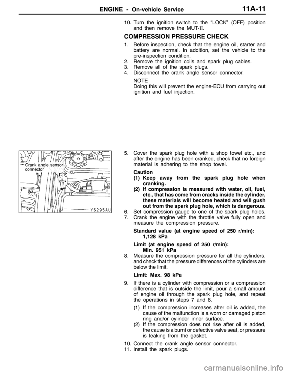
4. Disconnect the crank angle sensor connector.
NOTE
Doing this will prevent the engine-ECU from carrying out
ignition and fuel injection.
5. Cover the spark plug hole with a shop towel etc., and
after the engine has been cranked, check that no foreign
material is adhering to the shop towel.
Caution
(1) Keep away from the spark plug hole when
cranking.
(2) If compression is measured with water, oil, fuel,
etc., that has come from cracks inside the cylinder,
these materials will become heated and will gush
out from the spark plug hole, which is dangerous.
6. Set compression gauge to one of the spark plug holes.
7. Crank the engine with the throttle valve fully open and
measure the compression pressure.
Standard value (at engine speed of 250 r/min):
1,128 kPa
Limit (at engine speed of 250 r/min):
Min. 951 kPa
8. Measure the compression pressure for all the cylinders,
and check that the pressure differences of the cylinders are
below the limit.
Limit: Max. 98 kPa
9. If there is a cylinder with compression or a compression
difference that is outside the limit, pour a small amount
of engine oil through the spark plug hole, and repeat
the operations in steps 7 and 8.
(1) If the compression increases after oil is added, the
cause of the malfunction is a worn or damaged piston
ring and/or cylinder inner surface.
(2) If the compression does not rise after oil is added,
the cause is a burnt or defective valve seat, or pressure
is leaking from the gasket.
10. Connect the crank angle sensor connector.
11. Install the spark plugs.
Crank angle sensor
connector
Page 428 of 1449
ENGINE -Camshaft and Camshaft Oil Seal11A-22
"FACAMSHAFT POSITION SENSOR SUPPORT
INSTALLATION
1. Remove sealant remained on the camshaft position
sensor support.
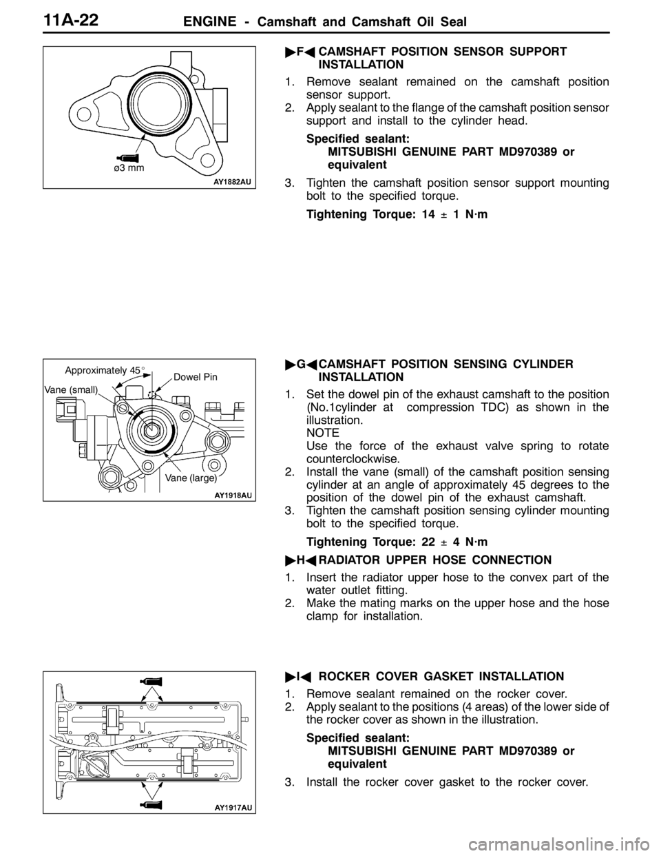
2. Apply sealant to the flange of the camshaft position sensor
support and install to the cylinder head.
Specified sealant:
MITSUBISHI GENUINE PART MD970389 or
equivalent
3. Tighten the camshaft position sensor support mounting
bolt to the specified torque.
Tightening Torque: 14±1 N·m
"GACAMSHAFT POSITION SENSING CYLINDER
INSTALLATION
1. Set the dowel pin of the exhaust camshaft to the position
(No.1cylinder at compression TDC) as shown in the
illustration.
NOTE
Use the force of the exhaust valve spring to rotate
counterclockwise.
2. Install the vane (small) of the camshaft position sensing
cylinder at an angle of approximately 45 degrees to the
position of the dowel pin of the exhaust camshaft.
3. Tighten the camshaft position sensing cylinder mounting
bolt to the specified torque.
Tightening Torque: 22±4 N·m
"HARADIATOR UPPER HOSE CONNECTION
1. Insert the radiator upper hose to the convex part of the
water outlet fitting.
2. Make the mating marks on the upper hose and the hose
clamp for installation.
"IAROCKER COVER GASKET INSTALLATION
1. Remove sealant remained on the rocker cover.
2. Apply sealant to the positions (4 areas) of the lower side of
the rocker cover as shown in the illustration.
Specified sealant:
MITSUBISHI GENUINE PART MD970389 or
equivalent
3. Install the rocker cover gasket to the rocker cover.
ø3 mm
Dowel Pin
Vane (small)
Approximately 45_
Vane (large)
Page 443 of 1449
ENGINE -Timing Belt and Timing Belt B11A-37
(1) Connect the special tool (MB991668) to the MUT-II.
(2) Connect the special tool (MB991704) to the MUT-II
and the battery.
(3) Rotate the crankshaft clockwise for two rounds to
position No.1 cylinder at compression TDC and check
that timing marks of each sprocket are aligned with
each other.
(4) Select “Belt Tension Measurement” from the menu
screen of the MUT-II.
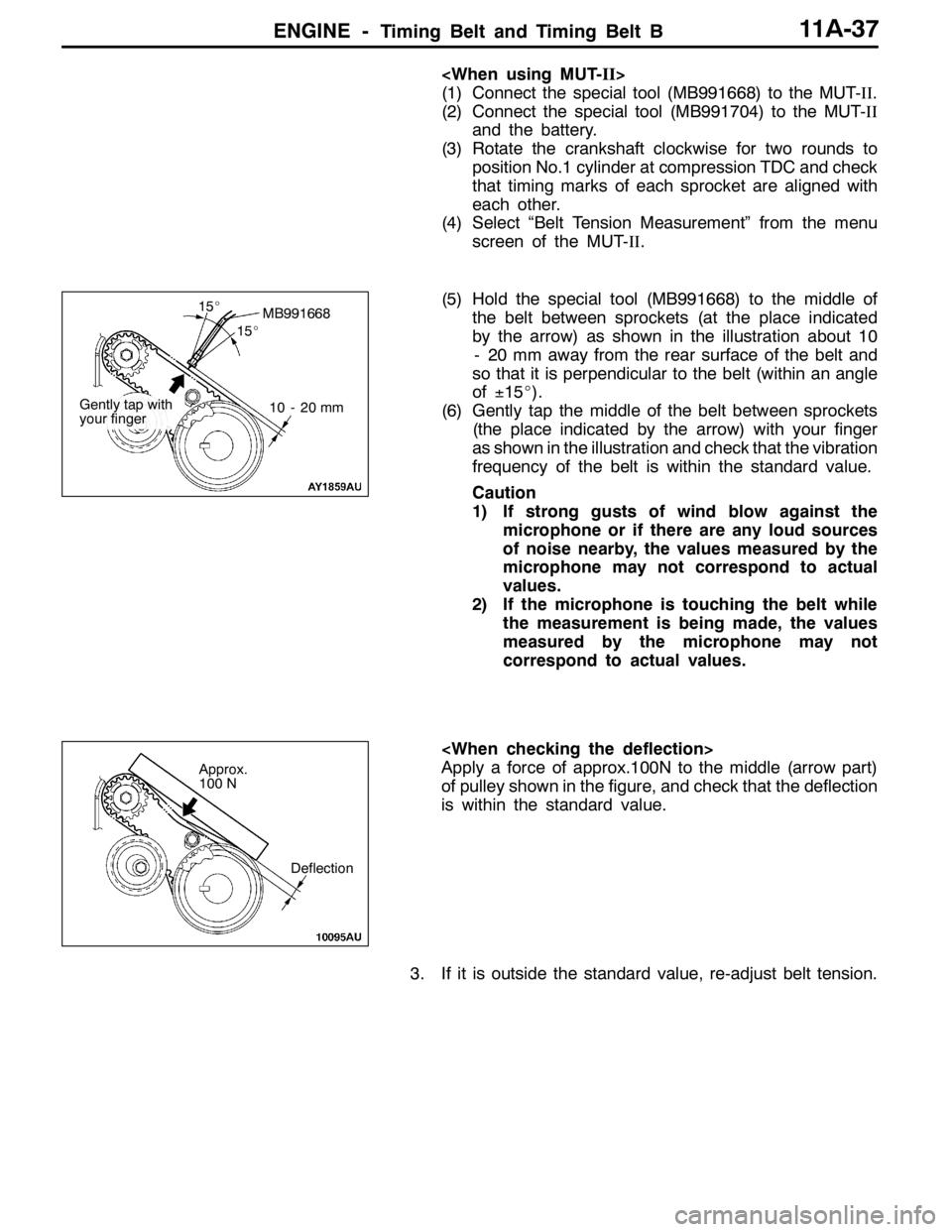
(5) Hold the special tool (MB991668) to the middle of
the belt between sprockets (at the place indicated
by the arrow) as shown in the illustration about 10
- 20 mm away from the rear surface of the belt and
so that it is perpendicular to the belt (within an angle
of±15_).
(6) Gently tap the middle of the belt between sprockets
(the place indicated by the arrow) with your finger
as shown in the illustration and check that the vibration
frequency of the belt is within the standard value.
Caution
1) If strong gusts of wind blow against the
microphone or if there are any loud sources
of noise nearby, the values measured by the
microphone may not correspond to actual
values.
2) If the microphone is touching the belt while
the measurement is being made, the values
measured by the microphone may not
correspond to actual values.
Apply a force of approx.100N to the middle (arrow part)
of pulley shown in the figure, and check that the deflection
is within the standard value.
3. If it is outside the standard value, re-adjust belt tension.
MB991668
10 - 20 mm
15_
15_
Gently tap with
your finger
Deflection
Approx.
100 N
Page 444 of 1449
ENGINE -Timing Belt and Timing Belt B11A-38
"CACRANKSHAFT SENSING BLADE/CRANKSHAFT
SPROCKET INSTALLATION
1. Clean and degrease the crankshaft sensing blade and
the crankshaft sprocket mounting surfaces of the
crankshaft sprocket and the crankshaft.
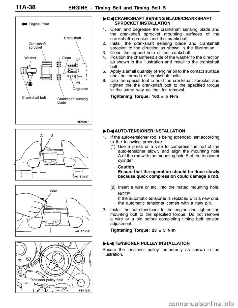
2. Install the crankshaft sensing blade and crankshaft
sprocket to the direction as shown in the illustration.
3. Clean the tapped hole of the crankshaft.
4. Position the chamfered side of the washer to the direction
as shown in the illustration and install to the crankshaft
bolt.
5. Apply a small quantity of engine oil to the contact surface
and the threads of crankshaft bolts.
6. Use the special tool to hold the crankshaft sprocket and
tighten the the crankshaft bolt to the specified torque
in the same way as that for removal.
Tightening Torque: 162±5 N·m
"DAAUTO-TENSIONER INSTALLATION
1. If the auto-tensioner rod is being extended, set according
to the following procedure.
(1) Use a press or a vise to compress the rod of the
auto-tensioner slowly and align the mounting hole
A of the rod with the mounting hole B of the tensioner
cylinder.
Caution
Ensure that the operation should be done slowly
because quick compression could damage a rod.
(2) Insert a wire or etc. into the mated mounting hole.
NOTE
If the automatic tensioner is replaced with a new one,
the automatic tensioner comes with a new pin.
2. Install the auto-tensioner to the engine and tighten the
mounting bolt to the specified torque. Do not remove
a wire or a pin before completing timing belt tension
adjustment.
Tightening Torque: 23±3 N·m
"EATENSIONER PULLEY INSTALLATION
Secure the tensioner pulley temporarily as shown in the
illustration.
Clean
Engine Front
Degrease
Crankshaft
Crankshaft
sprocket
Washer
Crankshaft boltCrankshaft sensing
blade
AB
Wire
Tensioner pulley hole
Page 447 of 1449
ENGINE -Timing Belt and Timing Belt B11A-41
2. Rotate the crankshaft counterclockwise for 1/4 round.
3. Rotate the crankshaft clockwise and mate timing marks
with each other to position No.1 cylinder at compression
TDC.
4. Loosen the temporarily tightened tensioner pulley
mounting bolt.
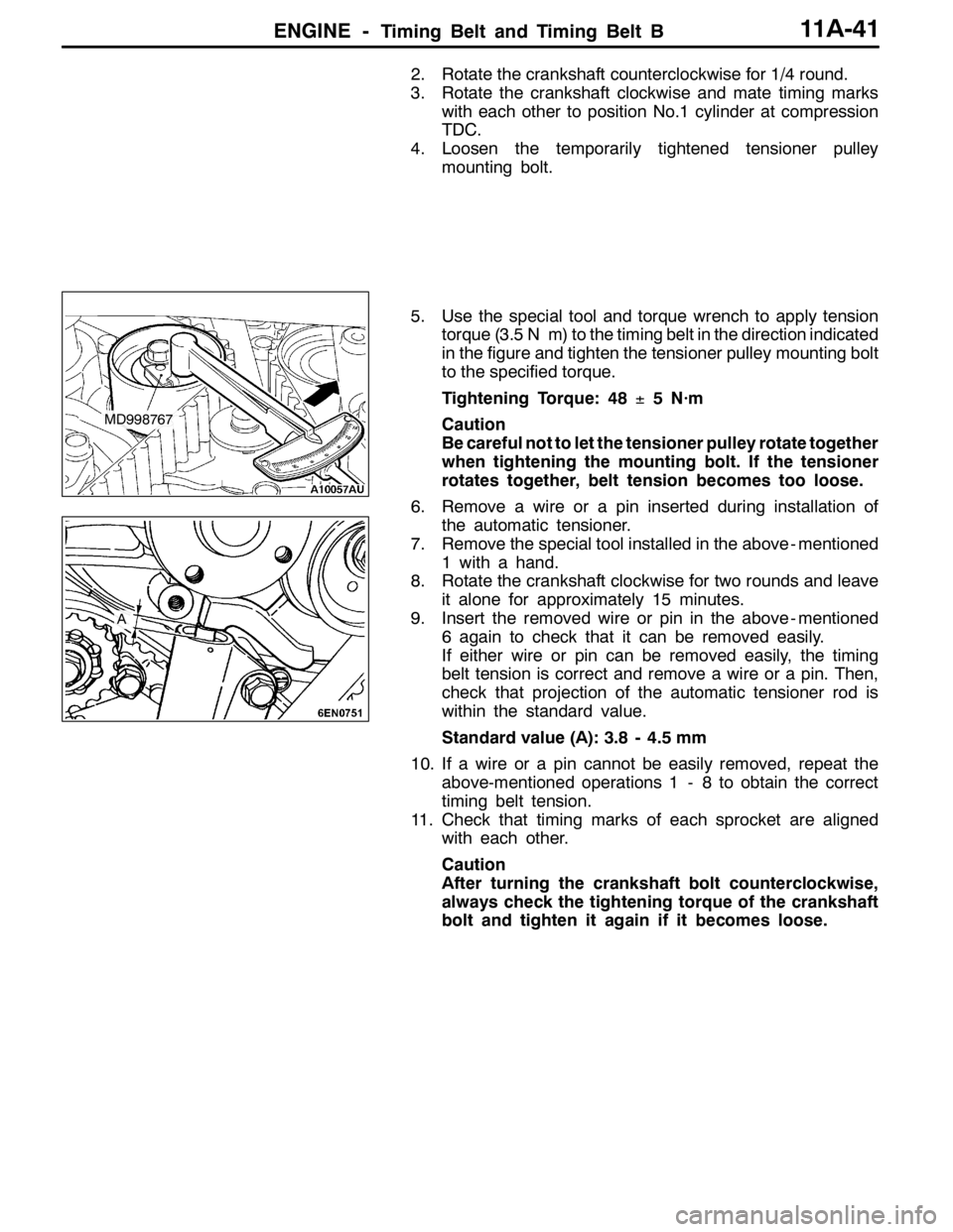
5. Use the special tool and torque wrench to apply tension
torque (3.5 N��m) to the timing belt in the direction indicated
in the figure and tighten the tensioner pulley mounting bolt
to the specified torque.
Tightening Torque: 48±5 N·m
Caution
Be careful not to let the tensioner pulley rotate together
when tightening the mounting bolt. If the tensioner
rotates together, belt tension becomes too loose.
6. Remove a wire or a pin inserted during installation of
the automatic tensioner.
7. Remove the special tool installed in the above - mentioned
1 with a hand.
8. Rotate the crankshaft clockwise for two rounds and leave
it alone for approximately 15 minutes.
9. Insert the removed wire or pin in the above - mentioned
6 again to check that it can be removed easily.
If either wire or pin can be removed easily, the timing
belt tension is correct and remove a wire or a pin. Then,
check that projection of the automatic tensioner rod is
within the standard value.
Standard value (A): 3.8 - 4.5 mm
10. If a wire or a pin cannot be easily removed, repeat the
above-mentioned operations 1 - 8 to obtain the correct
timing belt tension.
11. Check that timing marks of each sprocket are aligned
with each other.
Caution
After turning the crankshaft bolt counterclockwise,
always check the tightening torque of the crankshaft
bolt and tighten it again if it becomes loose.
MD998767
A
Page 456 of 1449

ENGINE OVERHAUL -General Description11B-2
GENERAL DESCRIPTION
LIST OF MODELS
Vehicle nameVehicle modelEngine modelDisplacement mLSpecifications
LANCER Evolution VIICT9A4G63 - 72000DOHC 16 valve T/C
SPECIFICATIONS
ItemsSpecifications
Bore×stroke mm85×88
Total displacement mL1,997
Combustion chamber shapePentroof type
Number of cylinders4
Valve mechanismTypeDOHC
Intake valve2
Exhaust valve2
Lash adjusterHydraulic type
Rocker armRoller follower type
Compression ratio8.8
Fuel injection deviceElectronic control MPI
Ignition device typeElectronic control type 2-coil
Alternator typeAlternating current type (IC regulator built in)
Starter motor typeDeceleration drive
Page 490 of 1449

ENGINE OVERHAUL -Rocker Arm and Camshaft11B-36
3. Apply sealant on the contact surfaces with the head shown
in the illustration.
Sealant
Specified sealant:
3M
TMAAD Part No. 8672 or equivalent
4. Install the bearing caps onto the cylinder head, and in
two to three steps tighten strongly.
5. Finally, tighten at the specified torque 20±1N•m.
6. Confirm that the rocker arm is correctly installed.
NOTE
Wipe off all excessive sealant.
"DACAMSHAFT OIL SEAL INSTALLATION
Install the oil seal using the special tool.
"EACAM POSITION SENSOR SUPPORT
INSTALLATION
Apply a 3 mm width of form-in-place gasket at the position
shown in the illustration.
Form-in-place gasket
Specified gasket:
Mitsubishi Genuine Part No. MD970389 or
equivalent
"FACAM POSITION SENSING CYLINDER
INSTALLATION
1. Set the exhaust camshaft at the No. 1 compression top
dead centre.
NOTE
The shaft will rotate slightly in the counterclockwise
direction by the force of the exhaust valve spring.
2. Install the cam position sensing cylinder’s vane (small)
and vane (large) at the positions shown in the illustration.
MD998713
Vane (small)
Cam position
sensorVane (large)
Page 595 of 1449
MPI -Troubleshooting13A-63
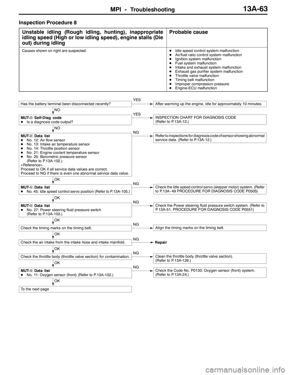
Inspection Procedure 8
Unstable idling (Rough idling, hunting), inappropriate
idling speed (High or low idling speed), engine stalls (Die
out) during idling
Probable cause
Causes shown on right are suspected.DIdle speed control system malfunction
DAir/fuel ratio control system malfunction
DIgnition system malfunction
DFuel system malfunction
DIntake and exhaust system malfunction
DExhaust gas purifier system malfunction
DThrottle valve malfunction
DTiming belt malfunction
DImproper compression pressure
DEngine-ECU malfunction
OK
To the next page
OK
MUT-IIData list
DNo. 11: Oxygen sensor (front) (Refer to P.13A-102.)NGCheck the Code No. P0130: Oxygen sensor (front) system.
(Refer to P.13A-24.)
OK
Check the throttle body (throttle valve section) for contamination.NGClean the throttle body (throttle valve section).
(Refer to P.13A-126.)
OK
Check the air intake from the intake hose and intake manifold.NG
Repair
OK
Check the timing marks on the timing belt.NGAlign the timing marks on the timing belt.
OK
MUT-IIData list
DNo. 27: Power steering fluid pressure switch
(Refer to P.13A-103.)NGCheck the Power steering fluid pressure switch system. (Refer to
P.13A-51, PROCEDURE FOR DAIGNOSIS CODE P0551)
OK
MUT-IIData list
DNo. 45: Idle speed control servo position (Refer to P.13A-105.)NGCheck the Idle speed control servo (stepper motor) system. (Refer
to P.13A - 49 PROCEDURE FOR DIAGNOSIS CODE P0505)
NO
MUT-IIData list
DNo. 12: Air flow sensor
DNo. 13: Intake air temperature sensor
DNo. 14: Throttle position sensor
DNo. 21: Engine coolant temperature sensor
DNo. 25: Barometric pressure sensor
(Refer to P.13A-102.)
Proceed to OK if all service data values are correct.
Proceed to NG if there is even one abnormal service data value.NGRefer to inspections for diagnosis code of sensor showing abnormal
service data. (Refer to P.13A-12.)
NO
MUT-IISelf-Diag code
DIs a diagnosis code output?YESINSPECTION CHART FOR DIAGNOSIS CODE
(Refer to P.13A-12.)
Has the battery terminal been disconnected recently?YESAfter warming up the engine, idle for approximately 10 minutes.