lock MITSUBISHI LANCER EVOLUTION 2007 Service Repair Manual
[x] Cancel search | Manufacturer: MITSUBISHI, Model Year: 2007, Model line: LANCER EVOLUTION, Model: MITSUBISHI LANCER EVOLUTION 2007Pages: 1449, PDF Size: 56.82 MB
Page 2 of 1449

WARNING REGARDING SERVICING OF SUPPLEMENTAL
RESTRAINT SYSTEM (SRS) EQUIPPED VEHICLE
WARNING!
(1) Improper service or maintenance of any component of the SRS, or any SRS-related component,
can lead to personal injury or death to service personnel (from inadvertent firing of the air
bag) or to the driver and passenger (from rendering the SRS inoperative).
(2) The SRS components should not be subjected to temperature of 93_C or more. So, remove
the SRS-ECU, driver’s and front passenger’s air bag modules and clock spring before drying
or baking the vehicle after painting.
(3) Service or maintenance of any SRS component or SRS-related component must be performed
only at an authorized MITSUBISHI dealer.
(4) MITSUBISHI dealer personnel must thoroughly review this manual, and especially its GROUP
52B - Supplemental Restraint System (SRS), before beginning any service or maintenance
of any SRS component or any SRS-related component.
NOTE
Section titles with asterisks (*) in the table of contents in each group indicate operations requiring warnings.
Page 5 of 1449

BODY CONSTRUCTION -Body ComponentsA-3
1. Headlamp support panel
2. Hood lock stay
3. Front end crossmember
4. Front end upper bar
5. Headlamp support panel side
6. Front fender shield
7. Front upper frame inner
8. Upper frame bulkhead front
9. Upper frame bulkhead
10. Upper frame bulkhead rear
11. Front sidemember inner
12. Engine mount bracket
13. Front sidemember rear
14. Front sidemember outer
15. Spring house panel
16. Dash panel
17. Dash panel silencer
18. Dash panel reinforcement
19. Upper frame to front pillar brace
20. Upper frame extension outer
21. Upper frame extension inner
22. Cowl top lower panel
23. Cowl top inner panel
24. Cowl top upper panel
25. Front deck crossmember
26. Hood inner panel
27. Hood outer panel
28. Front roof rail
29. Front roof bow
30. Roof panel
31. Rear roof bow
32. Rear roof rail
33. Seat back plate
34. Rear seat back panel
35. Rear shelf panel
36. Rear seat back brace
37. Trunk lid outer panel
38. Trunk lid inner panel
39. Trunk lid hinge
40. Quarter inner extension rear
41. Quarter corner panel42. Rear combination lamp housing
43. Side roof rail inner
44. Front pillar inner upper
45. Front pillar inner lower
46. Center pillar inner
47. Side outer panel
48. Rear wheel house inner panel
49. Quarter inner panel
50. Rear floor side brace
51. Quarter outer extension lower
52. Fuel filler door
53. Rear license plate bracket
54. Rear end panel outer
55. Rear end panel inner
56. Rear door outer panel
57. Rear door side door beam
58. Rear door inner panel
59. Front door outer panel
60. Front door side door beam
61. Front door inner panel
62. Fender panel
63. Front floor crossmember rear
64. Front floor crossmember front
65. Front floor side sill inner
66. Front floor sidemember
67. Backbone reinforcement
68. Installment panel center bracket reinforcement
69. Front floor pan
70. Front floor extension panel rear
71. Rear floor extension
72. Rear floor pan
73. Seat back plate extension
74. Jack bracket
75. Spare tire bracket
76. Towing hook reinforcement
77. Rear floor sidemember extension
78. Crossmember center support
79. Rear floor crossmember
80. Rear floor sidemember
81. Rear seat back reinforcement
Page 10 of 1449

BODY CONSTRUCTION -Body Construction CharacteristicsA-8
BODY CONSTRUCTION CHARACTERISTICS
FRONT BODY
Headlamp Support
1. By adopting a steel sheet with variable thickness* for the front end crossmember outer, the steel
sheet thickness on the right side of the vehicle has been increased to improve safety in collision
and body rigidity.
NOTE
*: Steel sheets with different thickness welded to formone steel sheet.
1
2 3
4 10 9
8765
1. Front end upper bar
2. Headlamp support panel
3. Hood lock stay
4. Front end crossmember inner reinforcement
5. A/C condenser bracket6. Radiator bracket
7. Front end crossmember inner
8. Front end crossmember outer
9. Shipping hook
10. Front end crossmember reinforcement
Page 88 of 1449

HOW TO READ THE WIRING DIAGRAMS -Composition and Contents of Wiring DiagramsA-2
COMPOSITION AND CONTENTS OF WIRING DIAGRAMS
(1) This manual consists of wiring harness diagrams, installation locations of individual parts, circuits
diagrams and index.
(2) In each section, all specifications are listed, including optional specifications. Accordingly, some
specifications may not be applicable for individual vehicles.
SectionBasic contents
Wiring harness
configuration
diagramsConnector locations and harness wiring configurations on actual vehicles are illustrated.
Single part
installation positionLocations are shown for each point of relays, electronic control units, sensors, solenoids,
solenoid valves, diodes, inspection connectors, spare connectors, fusible links, fuses, etc. In the
part’s lists, parts are listed in alphabetical order.
Circuit diagramsCircuits from power supply to earth are shown completely, classified according to system. There
is a main division into power circuits, and circuits classified by system. The circuits classified by
system also include operation and troubleshooting hints.
DJunction block
The entire circuit for the junction block is described, because only the part of the junction
block needed is normally shown in each circuit diagram.
DJoint connectors
The internal circuits for all joint connectors are described, because only the part needed
is shown in each circuit diagram.
DPower supply circuits
Circuits from the battery to fusible link, dedicated fuses, ignition switch, general purpose
fuses, etc.
DCircuits classified by system
For each system, the circuits are shown from fuse to earth, excluding the power supply
sections.
DOperation
The standard operation of each system is briefly described, following the route of current
flow.
DTroubleshooting hints
This is a brief explanation of the inspection points that serve as hints when troubleshooting.
Explanations of the circuits controlled by the electronic control unit are omitted. Refer
to the related publications as required.
IndexAll components used are listed by connector number and component name.
Page 89 of 1449

HOW TO READ THE WIRING DIAGRAMS -How to Read Configuration DiagramsA-3
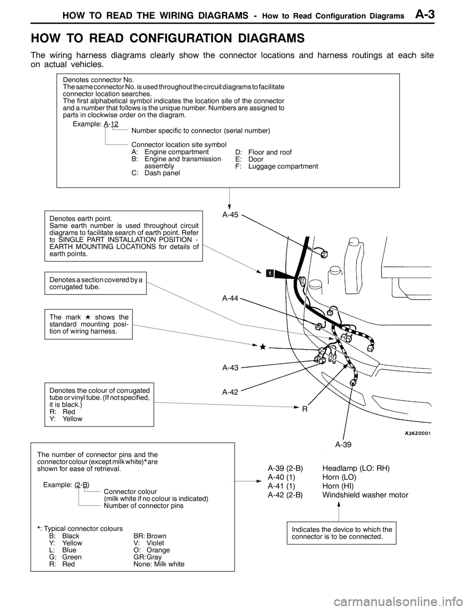
HOW TO READ CONFIGURATION DIAGRAMS
The wiring harness diagrams clearly show the connector locations and harness routings at each site
on actual vehicles.
Denotes connector No.
The same connector No. is used throughout the circuit diagrams to facilitate
connector location searches.
The first alphabetical symbol indicates the location site of the connector
and a number that follows is the unique number. Numbers are assigned to
parts in clockwise order on the diagram.
A-43
Example: A-12
Number specific to connector (serial number)
Connector location site symbol
A: Engine compartment
B: Engine and transmission
assembly
C: Dash panel
Denotes earth point.
Same earth number is used throughout circuit
diagrams to facilitate search of earth point. Refer
to SINGLE PART INSTALLATION POSITION -
EARTH MOUNTING LOCATIONS for details of
earth points.
Indicates the device to which the
connector is to be connected.
A-39 (2-B) Headlamp (LO: RH)
A-40 (1) Horn (LO)
A-41 (1) Horn (HI)
A-42 (2-B) Windshield washer motor
The number of connector pins and the
connector colour (except milk white)* are
shown for ease of retrieval.
Example: (2
-B)
Connector colour
(milk white if no colour is indicated)
Number of connector pins
*: Typical connector colours
B: Black
Y: Yellow
L: Blue
G: Green
R: Red
The markLshows the
standard mounting posi-
tion of wiring harness.
R
A-44
A-45
A-42
A-39
Denotes the colour of corrugated
tube or vinyl tube. (If not specified,
it is black.)
R: Red
Y: Yellow
Denotes a section covered by a
corrugated tube.
BR: Brown
V: Violet
O: Orange
GR: Gray
None: Milk whiteD: Floor and roof
E: Door
F: Luggage compartment
Page 90 of 1449

HOW TO READ THE WIRING DIAGRAMS -How to Read Circuit DiagramsA-4
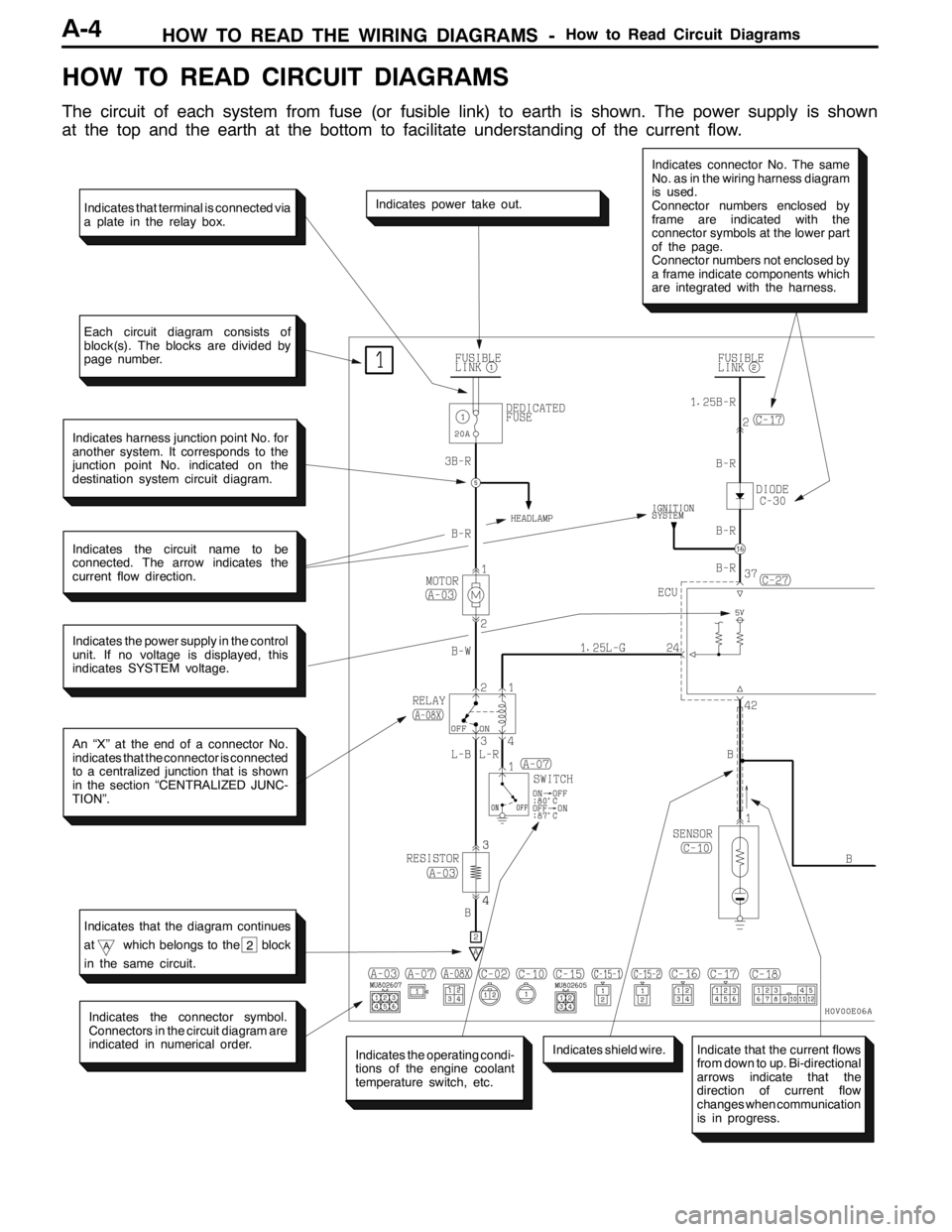
HOW TO READ CIRCUIT DIAGRAMS
The circuit of each system from fuse (or fusible link) to earth is shown. The power supply is shown
at the top and the earth at the bottom to facilitate understanding of the current flow.
Indicates the power supply in the control
unit. If no voltage is displayed, this
indicates SYSTEM voltage.
Indicates power take out.
Indicates connector No. The same
No. as in the wiring harness diagram
is used.
Connector numbers enclosed by
frame are indicated with the
connector symbols at the lower part
of the page.
Connector numbers not enclosed by
a frame indicate components which
are integrated with the harness.
Indicates harness junction point No. for
another system. It corresponds to the
junction point No. indicated on the
destination system circuit diagram.
Indicates the circuit name to be
connected. The arrow indicates the
current flow direction.
An “X” at the end of a connector No.
indicates that the connector is connected
to a centralized junction that is shown
in the section “CENTRALIZED JUNC-
TION”.
Indicates the operating condi-
tions of the engine coolant
temperature switch, etc.
Indicates the connector symbol.
Connectors in the circuit diagram are
indicated in numerical order.
Indicates shield wire.
Indicates that terminal is connected via
a plate in the relay box.
Each circuit diagram consists of
block(s). The blocks are divided by
page number.
Indicates that the diagram continues
at
Awhich belongs to the block
in the same circuit.2
Indicate that the current flows
from down to up. Bi-directional
arrows indicate that the
direction of current flow
changes when communication
is in progress.
Page 91 of 1449

HOW TO READ THE WIRING DIAGRAMS -How to Read Circuit DiagramsA-5
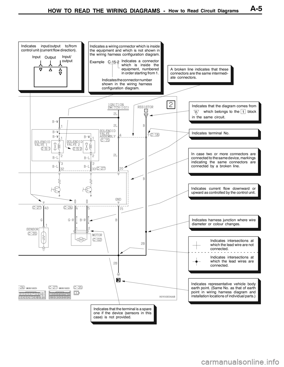
Indicates input/output to/from
control unit (current flow direction).
Input
OutputInput/
output
In case two or more connectors are
connected to the same device, markings
indicating the same connectors are
connected by a broken line.
Indicates current flow downward or
upward as controlled by the control unit.
Indicates harness junction where wire
diameter or colour changes.
Indicates intersections at
which the lead wire are not
connected.
Indicates intersections at
which the lead wires are
connected.
Indicates representative vehicle body
earth point. (Same No. as that of earth
point in wiring harness diagram and
installation locations of individual parts.)
Indicates that the terminal is a spare
one if the device (sensors in this
case) is not provided.
Indicates terminal No.
Indicates that the diagram comes from
Awhich belongs to the block
in the same circuit.1
A broken line indicates that these
connectors are the same intermedi-
ate connectors.
Indicates a wiring connector which is inside
the equipment and which is not shown in
the wiring harness configuration diagram.
Example C-15-2
Indicates the connector number
shown in the wiring harness
configuration diagram.Indicates a connector
which is inside the
equipment, numbered
in order starting from 1.
Page 97 of 1449

HOW TO READ THE WIRING DIAGRAMS -Abbreviation SymbolsHOW TO READ THE WIRING DIAGRAMS -Abbreviation SymbolsA-11
Name of switches and
relaysOperation Abbreviation
symbols
Dimmer passing
switch
LOLow beams ON
switch
HIHigh beams ON
PASS
Door lock actuatorLOCKDoor lock
UNLOCKDoor unlock
Headlamp leveling
switch
1Low beam light axis drops by one step
switch
2Low beam light axis drops by two step
3Low beam light axis drops by three step
4Low beam light axis drops by four step
Ignition switchACCWhen turned to the ACC (ACCESSORY) or ON position, the power
circuit will start
IG1Even when at the ST (START) position, the power circuit will start
IG2When at the ST (START) position, the power circuit will not start
functioning
Intercooler water spray
switch
MANUALWater is sprayed while the switch is being pressed
switch
AUTOWater is sprayed automatically according to driving conditions
Lighting switchTAILPosition, tail, licence plate and illumination lamps ON
HEADHeadlamps ON
OthersOFFSwitched OFF
ONSwitched ON
Power window switchUPWindow closes
DOWNWindow opens
AUTO UPWindow is easily closed with one action
AUTO DOWNWindow is easily opened with one action
LOCKPrevents all switches other than the main switch from operating the
power windows
Remote controlled
mirrorswitch
LHL.H. mirror operates
mirror switch
RHR.H. mirror operates
Room lamp switchDOORRoom lamp ON when a door is open
Turn signal switchLHL.H. signal lamps ON
RHR.H. signal lamps ON
Page 98 of 1449

HOW TO READ THE WIRING DIAGRAMS -Abbreviation SymbolsA-12
Name of switches and
relaysOperation Abbreviation
symbols
Windshield wiper
switch
MISTWiper operates once
switch
INTWiper operates intermittently
LOWiper operates at low speed
HIWiper operates at high speed
4. Other abbreviation symbols
Abbreviation
symbolsMeaningAbbreviation
symbolsMeaning
ECUElectronic control unitLCDLiquid crystal display
GNDEarthLHLeft hand
ILLIllumination lampLHDL.H. drive vehicles
INDIndicator lampRHRight hand
J/BJunction blockRHDR.H. drive vehicles
J/CJoint connector
Page 100 of 1449

B-2
S
PWGEE
IGNITION SYSTEM
L.H. drive vehicles 82.......................
R.H. drive vehicles 83.......................
CHARGING SYSTEM 84...................
ENGINE CONTROL SYSTEM
L.H. drive vehicles 86.......................
R.H. drive vehicles 94.......................
COOLING SYSTEM 102...................
HEADLAMP
L.H. drive vehicles 103......................
R.H. drive vehicles 106......................
TAIL LAMP, POSITION LAMP, LICENCE
PLATE LAMP AND LIGHTING MONITOR
BUZZER
L.H. drive vehicles 110......................
R.H. drive vehicles 114......................
ROOM LAMP AND LUGGAGE
COMPARTMENT LAMP
L.H. drive vehicles 118......................
R.H. drive vehicles 121......................
REAR FOG LAMP
L.H. drive vehicles 124......................
R.H. drive vehicles 127......................
HEADLAMP LEVELING SYSTEM
L.H. drive vehicles 130......................
R.H. drive vehicles 132......................
TURN-SIGNAL LAMP AND HAZARD
WARNING LAMP
L.H. drive vehicles 134......................
R.H. drive vehicles 138......................
BACK-UP LAMP
L.H. drive vehicles 142......................
R.H. drive vehicles 143......................
STOP LAMP
L.H. drive vehicles 144......................
R.H. drive vehicles 145......................
HORN 146................................
METER AND GAUGE
L.H. drive vehicles 148......................
R.H. drive vehicles 152......................
FUEL WARNING LAMP 156...............
OIL PRESSURE WARNING LAMP 157.....
BRAKE WARNING LAMP 157.............
POWER WINDOWS
L.H. drive vehicles 158......................
R.H. drive vehicles 164......................
CENTRAL DOOR LOCKING SYSTEM
L.H. drive vehicles 170......................
R.H. drive vehicles 172......................
HEATER AND MANUAL AIR CONDITIONER
L.H. drive vehicles 174......................
R.H. drive vehicles 180......................
DEFOGGER 185..........................
WINDSHIELD WIPER AND WASHER
L.H. drive vehicles 186......................
R.H. drive vehicles 189......................
REMOTE CONTROLLED MIRROR
L.H. drive vehicles 192......................
R.H. drive vehicles 193......................
CLOCK 194..............................
CIGARETTE LIGHTER AND ASHTRAY
ILLUMINATION LAMP 195.................
AUDIO SYSTEM 196......................