fuel filter MITSUBISHI LANCER EVOLUTION 2007 Service Repair Manual
[x] Cancel search | Manufacturer: MITSUBISHI, Model Year: 2007, Model line: LANCER EVOLUTION, Model: MITSUBISHI LANCER EVOLUTION 2007Pages: 1449, PDF Size: 56.82 MB
Page 662 of 1449

MPI -On-vehicle Service13A-130
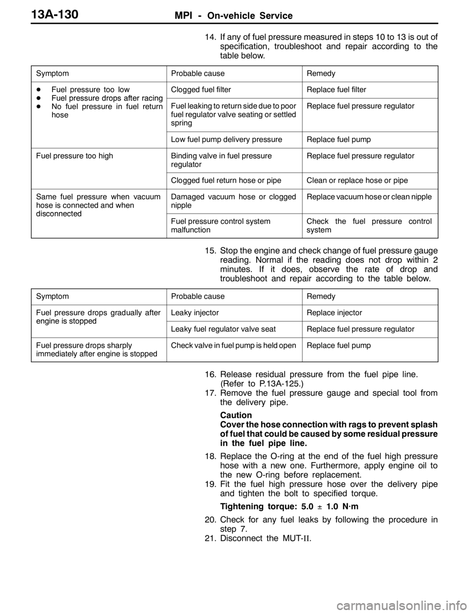
14. If any of fuel pressure measured in steps 10 to 13 is out of
specification, troubleshoot and repair according to the
table below.
SymptomProbable causeRemedy
DFuel pressure too low
DFuelpressuredropsafterracing
Clogged fuel filterReplace fuel filter
DFuelpressuredrops after racing
DNo fuel pressure in fuel return
hose
Fuel leaking to return side due to poor
fuel regulator valve seating or settled
springReplace fuel pressure regulator
Low fuel pump delivery pressureReplace fuel pump
Fuel pressure too highBinding valve in fuel pressure
regulatorReplace fuel pressure regulator
Clogged fuel return hose or pipeClean or replace hose or pipe
Same fuel pressure when vacuum
hose is connected and when
disconnected
Damaged vacuum hose or clogged
nippleReplace vacuum hose or clean nipple
disconnectedFuel pressure control system
malfunctionCheck the fuel pressure control
system
15. Stop the engine and check change of fuel pressure gauge
reading. Normal if the reading does not drop within 2
minutes. If it does, observe the rate of drop and
troubleshoot and repair according to the table below.
SymptomProbable causeRemedy
Fuel pressure drops gradually after
engineisstopped
Leaky injectorReplace injector
engineisstopped
Leaky fuel regulator valve seatReplace fuel pressure regulator
Fuel pressure drops sharply
immediately after engine is stoppedCheck valve in fuel pump is held openReplace fuel pump
16. Release residual pressure from the fuel pipe line.
(Refer to P.13A-125.)
17. Remove the fuel pressure gauge and special tool from
the delivery pipe.
Caution
Cover the hose connection with rags to prevent splash
of fuel that could be caused by some residual pressure
in the fuel pipe line.
18. Replace the O-ring at the end of the fuel high pressure
hose with a new one. Furthermore, apply engine oil to
the new O-ring before replacement.
19. Fit the fuel high pressure hose over the delivery pipe
and tighten the bolt to specified torque.
Tightening torque: 5.0±1.0 N·m
20. Check for any fuel leaks by following the procedure in
step 7.
21. Disconnect the MUT-II.
Page 682 of 1449

FUEL SUPPLY - General Information/On-vehicle Service13B-2
GENERAL INFORMATION
DThe steel fuel tank is located under the floor of the rear seats to provide increased safety and increase
the amount of luggage compartment space.
DThe fuel tank has been equipped with a valve assembly which incorporates a fuel cut-off valve to
prevent fuel from leaking out in the event of a collision for adjusting the pressure inside the fuel
tank.
DThe fuel pump module contains a fuel pump, fuel filter, and fuel pressure regulator.
ON-VEHICLE SERVICE
FUEL PUMP AND GAUGE ASSEMBLY (FUEL
PUMP)
1. FUEL PUMP OPERATION CHECK
Refer to GROUP 13A - On-vehicle service
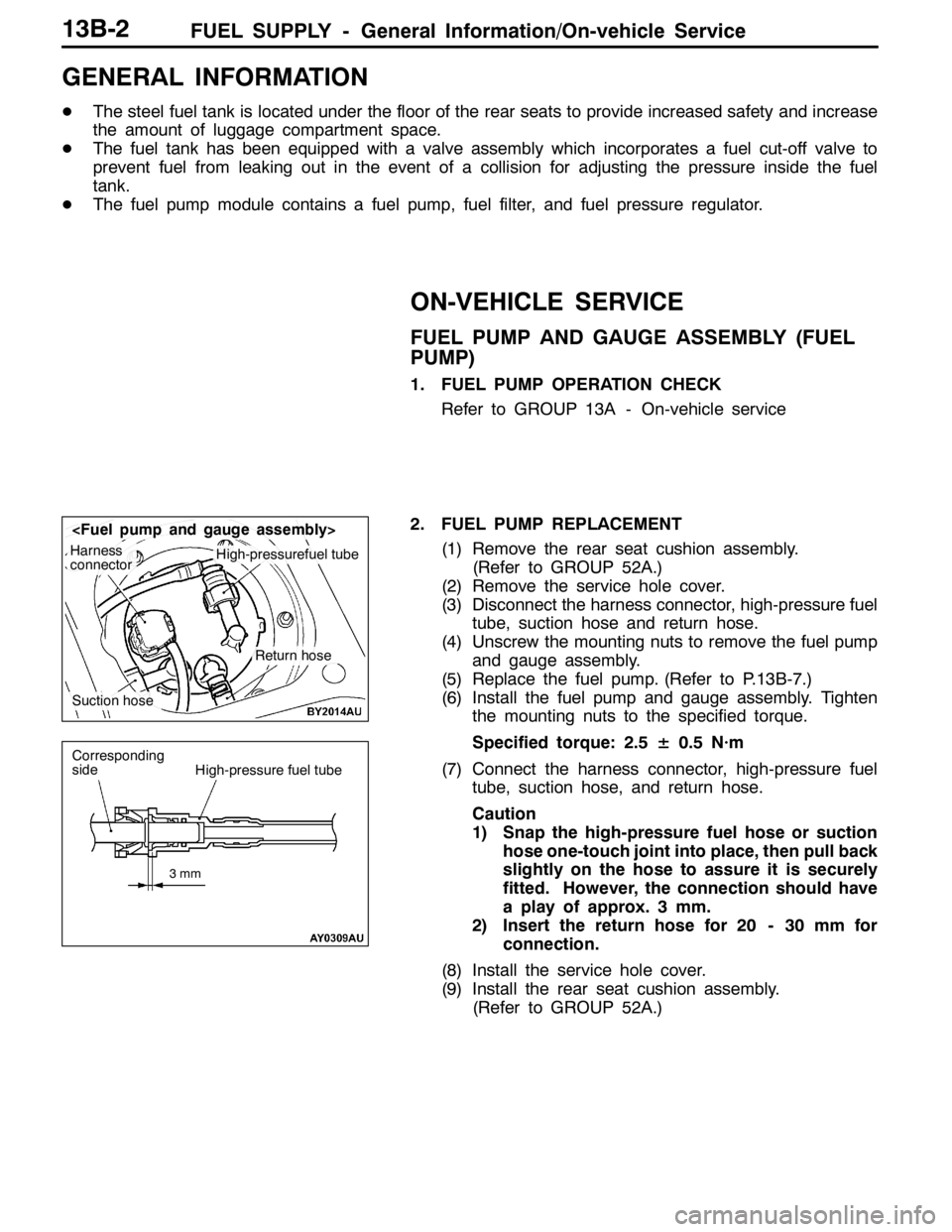
2. FUEL PUMP REPLACEMENT
(1) Remove the rear seat cushion assembly.
(Refer to GROUP 52A.)
(2) Remove the service hole cover.
(3) Disconnect the harness connector, high-pressure fuel
tube, suction hose and return hose.
(4) Unscrew the mounting nuts to remove the fuel pump
and gauge assembly.
(5) Replace the fuel pump. (Refer to P.13B-7.)
(6) Install the fuel pump and gauge assembly. Tighten
the mounting nuts to the specified torque.
Specified torque: 2.5± 0.5 N·m
(7) Connect the harness connector, high-pressure fuel
tube, suction hose, and return hose.
Caution
1) Snap the high-pressure fuel hose or suction
hose one-touch joint into place, then pull back
slightly on the hose to assure it is securely
fitted. However, the connection should have
a play of approx. 3 mm.
2) Insert the return hose for 20 - 30 mm for
connection.
(8) Install the service hole cover.
(9) Install the rear seat cushion assembly.
(Refer to GROUP 52A.)
Harness
connectorHigh-pressurefuel tube
Suction hose
Return hose
3mm
Corresponding
sideHigh-pressure fuel tube
Page 687 of 1449

FUEL SUPPLY - Fuel Tank13B-7
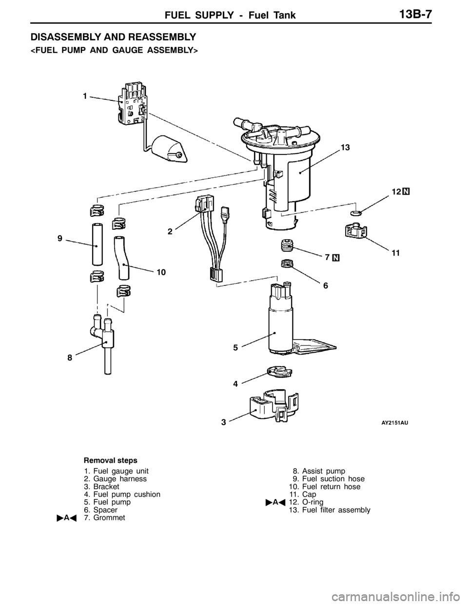
DISASSEMBLY AND REASSEMBLY
1
2
34 567
9
8101112 13
Removal steps
1. Fuel gauge unit
2. Gauge harness
3. Bracket
4. Fuel pump cushion
5. Fuel pump
6. Spacer
"AA7. Grommet8. Assist pump
9. Fuel suction hose
10. Fuel return hose
11. Cap
"AA12. O-ring
13. Fuel filter assembly
Page 688 of 1449

FUEL SUPPLY - Fuel Tank13B-8
236
1 4
5
1.2±0.2 N·m
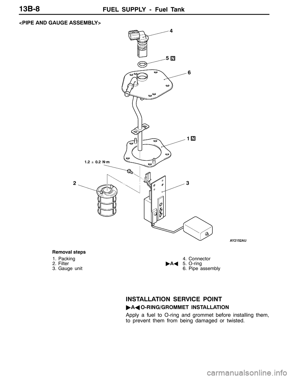
Removal steps
1. Packing
2. Filter
3. Gauge unit4. Connector
"AA5. O-ring
6. Pipe assembly
INSTALLATION SERVICE POINT
"AAO-RING/GROMMET INSTALLATION
Apply a fuel to O-ring and grommet before installing them,
to prevent them from being damaged or twisted.