oil filter MITSUBISHI LANCER EVOLUTION 2007 Service Repair Manual
[x] Cancel search | Manufacturer: MITSUBISHI, Model Year: 2007, Model line: LANCER EVOLUTION, Model: MITSUBISHI LANCER EVOLUTION 2007Pages: 1449, PDF Size: 56.82 MB
Page 461 of 1449

ENGINE OVERHAUL -Specifications11B-7
Items Tightening torque N·m
Water outlet fitting bolt10±1
Thermostat housing bolt23±4
Water inlet pipe bolt (M6)10±1
Water inlet pipe bolt (M8)13±2
Water pump bolt14±1
Knock sensor23±2
Rocker arm, camshaft
Cam position sensor bolt8.8±1.0
Cover bolt10±2
Cam position sensing cylinder bolt22±4
Cam position sensor support bolt14±1
Bearing cap bolt20±1
Oil delivery body bolt11±1
Cylinder head, valve
Cylinder head bolt78±2→Completely loosen→20±2→90_+90_
Oil pump, oil pan
Drain plug39±5
Oil pan bolt9±3
Oil screen bolt19±3
Baffle plate bolt22±4
Oil pressure switch19±3
Oil cooler bypass valve54±5
Relief plug44±5
Oil filter bracket bolt19±3
Plug cap23±3
Flange bolt36±3
Oil pump case bolt23±3
Oil pump cover bolt17±1
Oil pump cover screw10±2
Piston, connecting rod
Connecting rod cap nut20±2+90_-94_
Crankshaft, cylinder block
Flywheel bolt132±5
Rear plate bolt11±1
Bell housing cover bolt9±1
Rear oil seal case bolt11±1
Beam bearing cap bolt25±2+90_- 100_
Check valve32±2
Throttle body
Throttle position sensor bolt2.0±0.5
Turbocharger
Waste gate actuator bolt11.3±1.5
Page 501 of 1449

ENGINE OVERHAUL -Oil Pump and Oil Pan11B-47
OIL PUMP AND OIL PAN
REMOVAL AND INSTALLATION
2
1
Apply engine oil on
all sliding sections
before installing.
4 56
12 13
16187 20
38
9
10 1415
1719
1139±5N•m 54±5N•m19±3N•m
36±3N•m23±3N•m 17±1N•m 10±2N•m
9±3N•m 22±4N•m 23±3N•m
19±3N•m
44±5N•m 23±3N•m
25
24232221
26272930
31
28
19±3N•m
Removal steps
1. Drain plug
"NA2. Drain plug gasket
"MA3. Oil filter
AA""LA4. Oil pan
5. Oil screen
6. Oil screen gasket
7. Baffle plate
"KA8. Oil pressure switch
9. Oil cooler bypass valve
10. Relief plug
11. Gasket
12. Relief spring
13. Relief plunger
14. Oil filter bracket
15. Oil filter bracket gasket
AB""JA16. Plug cap
17. O-ringAC""IA18. Flange bolt
"HA19. Oil pump case
20. Oil pump case gasket
21. Oil pump cover
"GA22. Oil pump driven gear
"GA23. Oil pump drive gear
"FA24. Crankshaft front oil seal
"EA25. Counter balance shaft oil seal
"DA26. Oil pump oil seal
27. Counter balance shaft, right
28. Counter balance shaft, left
AD""CA29. Counter balance shaft front bearing
AE""BA30. Counter balance shaft rear bearing,
right
AE""AA31. Counter balance shaft rear bearing,
left
Page 506 of 1449

ENGINE OVERHAUL -Oil Pump and Oil Pan11B-52
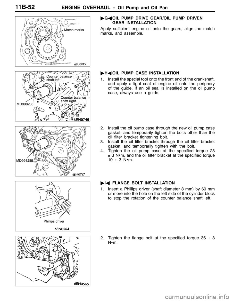
"GAOIL PUMP DRIVE GEAR/OIL PUMP DRIVEN
GEAR INSTALLATION
Apply sufficient engine oil onto the gears, align the match
marks, and assemble.
"HAOIL PUMP CASE INSTALLATION
1. Install the special tool onto the front end of the crankshaft,
and apply a light coat of engine oil onto the periphery
of the guide. If an oil seal is installed on the oil pump
case, always use a guide.
2. Install the oil pump case through the new oil pump case
gasket, and temporarily tighten the bolts other than the
oil filter bracket tightening bolt.
3. Install the oil filter bracket through the oil filter bracket
gasket, and temporarily tighten with the bolt.
4. Tighten the oil pump case at the specified torque 23
±3N•m, and the oil filter bracket at the specified torque
19±3N•m.
"IAFLANGE BOLT INSTALLATION
1. Insert a Phillips driver (shaft diameter 8 mm) by 60 mm
or more into the hole on the left side of the cylinder block
to stop the rotation of the counter balance shaft left.
2. Tighten the flange bolt at the specified torque 36±3
N•m.
Match marks
MD998285
Counter balance
shaft left
Counter balance
shaft right
MD998285
Phillips driver
Page 508 of 1449

ENGINE OVERHAUL -Oil Pump and Oil Pan11B-54
"MADRAIN PLUG GASKET INSTALLATION
Replace the gasket with a new part, and install at the direction
shown in the illustration.
Caution
Incorrect installation direction will lead to oil leaks.
"NAOIL FILTER INSTALLATION
1. Clean the installation surface on the cylinder block side.
2. Apply engine oil on the O-ring for the oil filter.
3. Screw in the oil filter, and tighten approx. 3/4 of a rotation
(approx. 14±2N•m) from where the O-ring contacts
the installation surface.
INSPECTION
1. COUNTER BALANCE SHAFT
(1) Make sure that the oil hole is not clogged.
(2) Check the journal (bearing section) for seizure or
damage, and check the state of contact with the
bearings. If any faults are found, replace the counter
balance shaft, bearing or oil pump case assembly.
2. OIL COOLER BYPASS VALVE
(1) The valve must move smoothly.
(2) The L dimension must be at the standard value at
a constant temperature, constant humidity state.
Standard value: 34.5 mm
(3) The protruded dimensions must be at the standard
value after submerging into 100_C oil.
Standard value: 40 mm
Drain plug
Oil pan
Oil pan side Gasket
Bracket side
L
Valve
Page 525 of 1449

12-1
ENGINE
LUBRICATION
CONTENTS
GENERAL INFORMATION 2..................
SERVICE SPECIFICATIONS 3.................
SEALANT 3..................................
LUBRICANTS 3..............................
SPECIAL TOOL 3............................ON-VEHICLE SERVICE 4.....................
Engine Oil Check 4............................
Engine Oil Replacement 4.......................
Oil Filter Replacement 5........................
Oil Pressure Check 5..........................
ENGINE OIL COOLER 7......................
Page 527 of 1449

ENGINE LUBRICATION -Service Specifications/Sealant/Lubricants/Special Tool12-3
SERVICE SPECIFICATIONS
ItemsStandard value
Oil pressure kPaat idle29 or more
at 3,500 r/min294 - 686
SEALANT
ItemsSpecified sealantRemark
Oil pressure switch3M ATD Part No. 8660 or equivalentSemi-drying sealant
LUBRICANTS
ItemsSpecifications
Engine oil ACEA classificationFor EuropeA1, A2, A3
Engine oil API classificationFor EuropeSG or higher
For General ExportSE or higher
Engine oil quantity LOil filter0.3
Oil cooler0.3
Total5.1
SPECIAL TOOL
ToolNumberNameUse
MD998054Oil pressure switch
wrenchRemoval and installation of oil pressure switch
Page 528 of 1449

ENGINE LUBRICATION -On-vehicle Service12-4
ON-VEHICLE SERVICE
ENGINE OIL CHECK
1. Pull out the level gauge slowly and check that the oil
level is in the illustrated range.
2. Check that the oil is not excessively dirty, that there is
no coolant or petrol mixed in, and that it has sufficient
viscosity.
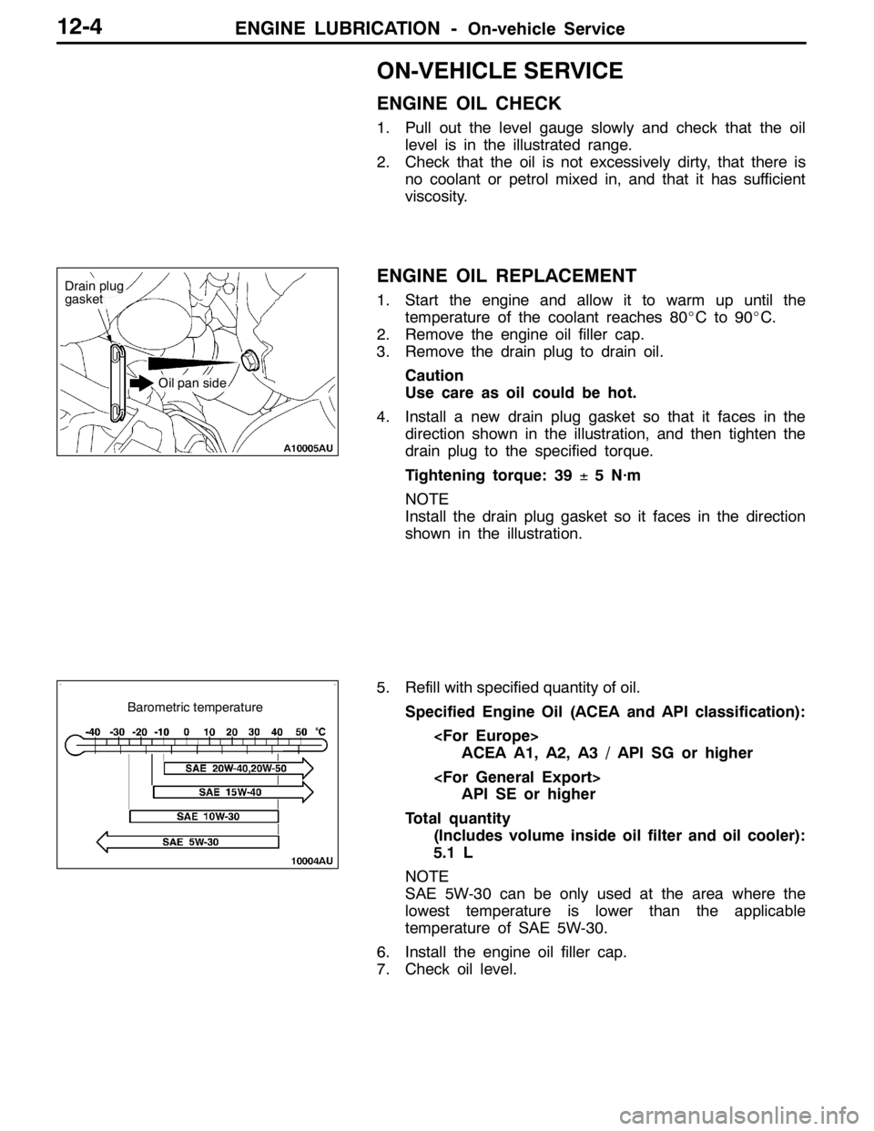
ENGINE OIL REPLACEMENT
1. Start the engine and allow it to warm up until the
temperature of the coolant reaches 80_Cto90_C.
2. Remove the engine oil filler cap.
3. Remove the drain plug to drain oil.
Caution
Use care as oil could be hot.
4. Install a new drain plug gasket so that it faces in the
direction shown in the illustration, and then tighten the
drain plug to the specified torque.
Tightening torque: 39±5 N·m
NOTE
Install the drain plug gasket so it faces in the direction
shown in the illustration.
5. Refill with specified quantity of oil.
Specified Engine Oil (ACEA and API classification):
ACEA A1, A2, A3 / API SG or higher
API SE or higher
Total quantity
(Includes volume inside oil filter and oil cooler):
5.1 L
NOTE
SAE 5W-30 can be only used at the area where the
lowest temperature is lower than the applicable
temperature of SAE 5W-30.
6. Install the engine oil filler cap.
7. Check oil level.
Drain plug
gasket
Oil pan side
Barometric temperature
Page 529 of 1449

ENGINE LUBRICATION -On-vehicle Service12-5
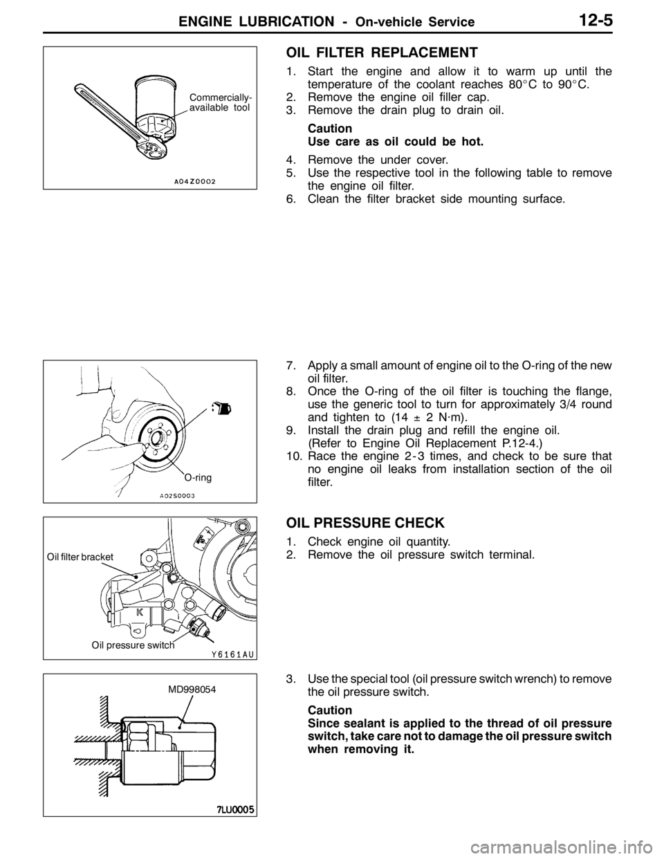
OIL FILTER REPLACEMENT
1. Start the engine and allow it to warm up until the
temperature of the coolant reaches 80_Cto90_C.
2. Remove the engine oil filler cap.
3. Remove the drain plug to drain oil.
Caution
Use care as oil could be hot.
4. Remove the under cover.
5. Use the respective tool in the following table to remove
the engine oil filter.
6. Clean the filter bracket side mounting surface.
7. Apply a small amount of engine oil to the O-ring of the new
oil filter.
8. Once the O-ring of the oil filter is touching the flange,
use the generic tool to turn for approximately 3/4 round
and tighten to (14±2 N·m).
9. Install the drain plug and refill the engine oil.
(Refer to Engine Oil Replacement P.12-4.)
10. Race the engine 2 - 3 times, and check to be sure that
no engine oil leaks from installation section of the oil
filter.
OIL PRESSURE CHECK
1. Check engine oil quantity.
2. Remove the oil pressure switch terminal.
3. Use the special tool (oil pressure switch wrench) to remove
the oil pressure switch.
Caution
Since sealant is applied to the thread of oil pressure
switch, take care not to damage the oil pressure switch
when removing it.
Commercially-
available tool
O-ring
Oil pressure switch
Oil filter bracket
MD998054
Page 662 of 1449

MPI -On-vehicle Service13A-130
14. If any of fuel pressure measured in steps 10 to 13 is out of
specification, troubleshoot and repair according to the
table below.
SymptomProbable causeRemedy
DFuel pressure too low
DFuelpressuredropsafterracing
Clogged fuel filterReplace fuel filter
DFuelpressuredrops after racing
DNo fuel pressure in fuel return
hose
Fuel leaking to return side due to poor
fuel regulator valve seating or settled
springReplace fuel pressure regulator
Low fuel pump delivery pressureReplace fuel pump
Fuel pressure too highBinding valve in fuel pressure
regulatorReplace fuel pressure regulator
Clogged fuel return hose or pipeClean or replace hose or pipe
Same fuel pressure when vacuum
hose is connected and when
disconnected
Damaged vacuum hose or clogged
nippleReplace vacuum hose or clean nipple
disconnectedFuel pressure control system
malfunctionCheck the fuel pressure control
system
15. Stop the engine and check change of fuel pressure gauge
reading. Normal if the reading does not drop within 2
minutes. If it does, observe the rate of drop and
troubleshoot and repair according to the table below.
SymptomProbable causeRemedy
Fuel pressure drops gradually after
engineisstopped
Leaky injectorReplace injector
engineisstopped
Leaky fuel regulator valve seatReplace fuel pressure regulator
Fuel pressure drops sharply
immediately after engine is stoppedCheck valve in fuel pump is held openReplace fuel pump
16. Release residual pressure from the fuel pipe line.
(Refer to P.13A-125.)
17. Remove the fuel pressure gauge and special tool from
the delivery pipe.
Caution
Cover the hose connection with rags to prevent splash
of fuel that could be caused by some residual pressure
in the fuel pipe line.
18. Replace the O-ring at the end of the fuel high pressure
hose with a new one. Furthermore, apply engine oil to
the new O-ring before replacement.
19. Fit the fuel high pressure hose over the delivery pipe
and tighten the bolt to specified torque.
Tightening torque: 5.0±1.0 N·m
20. Check for any fuel leaks by following the procedure in
step 7.
21. Disconnect the MUT-II.
Page 1123 of 1449

STEERING -On-vehicle Service37A-9
POWER STEERING FLUID LEVEL CHECK
1. Park the vehicle on a flat, level surface, start the engine,
and then turn the steering wheel several times to raise
the temperature of the fluid to approximately 50 - 60_C.
2. With the engine running, turn the wheel all the way to
the left and right several times.
3. Check the fluid in the oil reservoir for foaming or milkiness.
Check the difference of the fluid level when the engine
is stopped, and while it is running. If the change of the
fluid level is 5 mm or more, air bleeding should be done.
POWER STEERING FLUID REPLACEMENT
1. Raise the front wheels on a jack, and then support them
with rigid racks.
2. Disconnect the return hose connection.
3. Connect a vinyl hose to the return hose, and drain the
oil into a container.
4. Disconnect the ignition coil connectors. (Refer to
GROUP16 - Ignition System.)
5. While operating the starting motor intermittently, turn the
steering wheel all the way to the left and right several
times to drain all of the fluid.
6. Connect the return hoses securely, and then secure it
with the clip.
7. Fill the oil reservoir with specified fluid up to the lower
position of the filter, and then bleed air.
Specified fluid:
Automatic transmission fluid DEXRONII
Caution
Do not use ATF-SPIIM and ATF-SPIII.
POWER STEERING SYSTEM BLEEDING
1. Jack up the vehicle and support the front wheels with
rigid racks.
2. Disconnect the ignition coil connectors. (Refer to
GROUP16 - Ignition System.)
3. Cranking the engine with the starter several times
intermittently (during 15 to 20 seconds), turn the steering
wheel left and right fully five or six times.
Caution
(1) During the bleeding, refill the fluid so that the
level never falls below the lower position of the
filter.
(2) Be sure to bleed air only while cranking. If the
bleeding is done with the engine running, the air
will be broken up and absorbed into the fluid.
4. Connect the ignition coil connectors and idle the engine.
5. Turn the steering wheel left and right fully until no bubbles
comes out in the oil reservoir.
6. See that the fluid is not milky and that the fluid level
is up to the specified position on the level gauge.
7. See that the fluid level changes little when the steering
wheel is turned left and right.
8. Check difference in fluid levels between the engine
stopped and running.
Fluid level change: Within 5 mm
While engine
runningWhile engine
stopped
Return hose
Vinyl hose