transmission MITSUBISHI LANCER EVOLUTION 2007 Service Repair Manual
[x] Cancel search | Manufacturer: MITSUBISHI, Model Year: 2007, Model line: LANCER EVOLUTION, Model: MITSUBISHI LANCER EVOLUTION 2007Pages: 1449, PDF Size: 56.82 MB
Page 1 of 1449
00
11
12
13
14
15
16
17
21
22
25
26
27
31
32
33
34
35
36
37
42
51
52
54
55
General........................
Engine .........................
Engine Lubrication .............
Fuel ...........................
Engine Cooling .................
Intake and Exhaust ............
Engine Electrical ...............
Engine and Emission Control ....
Clutch .........................
Manual Transmission ...........
Propeller Shaft .................
Front Axle ......................
Rear Axle ......................
Wheel and Tyre .................
Power Plant Mount ..............
Front Suspension ...............
Rear Suspension ...............
Service Brakes .................
Parking Brakes .................
Steering ........................
Body ...........................
Exterior ........................
Chassis Electrical ..............
Electrical Wiring ................
Body Repair ....................
WORKSHOP
MANUAL
FOREWORD
This Workshop Manual contains procedures for
service mechanics, including removal, disassembly,
inspection, adjustment, reassembly and
installation. Use the following manuals in
combination with this manual as required.
TECHNICAL INFORMATION MANUAL N0104CT9A
All information, illustrations and product
descriptions contained in this manual are current
as at the time of publication. We, however, reserve
the right to make changes at any time without prior
notice or obligation.
The EVOLUTION-VII is sold exclusively through
RALLIART Inc. Since the EVOLUTION-VII is a
rally-based model, it will not be warranted and will
not be homologated for general production.
Therefore, any service matters on the
EVOLUTION-VII should be inquired to RALLIART
Inc. as usual.
EMitsubishi Motors Corporation May 2001
Interior and Supplemental
Restraint System (SRS) ........
Heater, Air Conditioner and
Ventilation .....................
Page 11 of 1449
BODY CONSTRUCTION -Body Construction CharacteristicsA-9
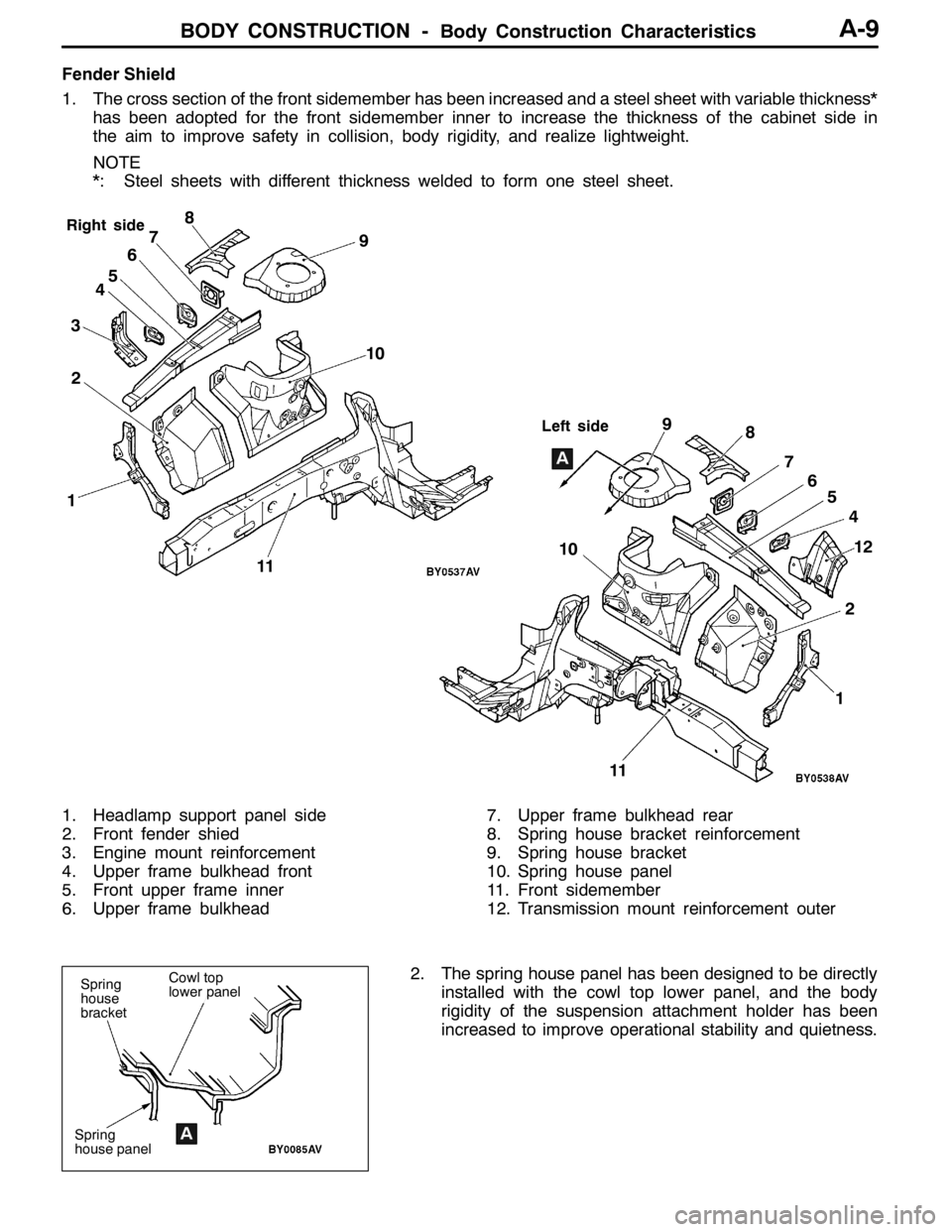
Fender Shield
1. The cross section of the front sidemember has been increased and a steel sheet with variable thickness*
has been adopted for the front sidemember inner to increase the thickness of the cabinet side in
the aim to improve safety in collision, body rigidity, and realize lightweight.
NOTE
*: Steel sheets with different thickness welded to form one steel sheet.
12 345678
9
1112
Right side
Left side
10
10
124 5 6 7 8 9
A
11
1. Headlamp support panel side
2. Front fender shied
3. Engine mount reinforcement
4. Upper frame bulkhead front
5. Front upper frame inner
6. Upper frame bulkhead7. Upper frame bulkhead rear
8. Spring house bracket reinforcement
9. Spring house bracket
10. Spring house panel
11. Front sidemember
12. Transmission mount reinforcement outer
2. The spring house panel has been designed to be directly
installed with the cowl top lower panel, and the body
rigidity of the suspension attachment holder has been
increased to improve operational stability and quietness.
Spring
house
bracket
Spring
house panelA
Cowl top
lower panel
Page 13 of 1449

BODY CONSTRUCTION -Body Construction Characteristics
A
713
12
B
11
712
A-11
Left side
23
7 8 456789
10
11
AB
310
1112
13
14 15 16 17
18
19
20 21 1
13
18
1. Suspension crossmember support bracket
2. Dash crossmember extension
3. Front sidemember rear
4. Pipe nut
5. Pipe support rear
6. Dash panel extension
7. Front sidemember inner
8. Front sidemember inner reinforcement rear
9. Front sidemember gusset rear
10. Front sidemember bulkhead rear
11. Front sidemember inner reinforcement12. Front sidemember outer
13. Front sidemember bulkhead A
14. Pipe
15. Square head bolt
16. Retainer
17. Pipe support front
18. Suspension crossmember bracket inner
19. Transmission mount reinforcement
20. Transmission mount bracket
21. Transmission mount reinforcement rear
Page 89 of 1449
HOW TO READ THE WIRING DIAGRAMS -How to Read Configuration DiagramsA-3
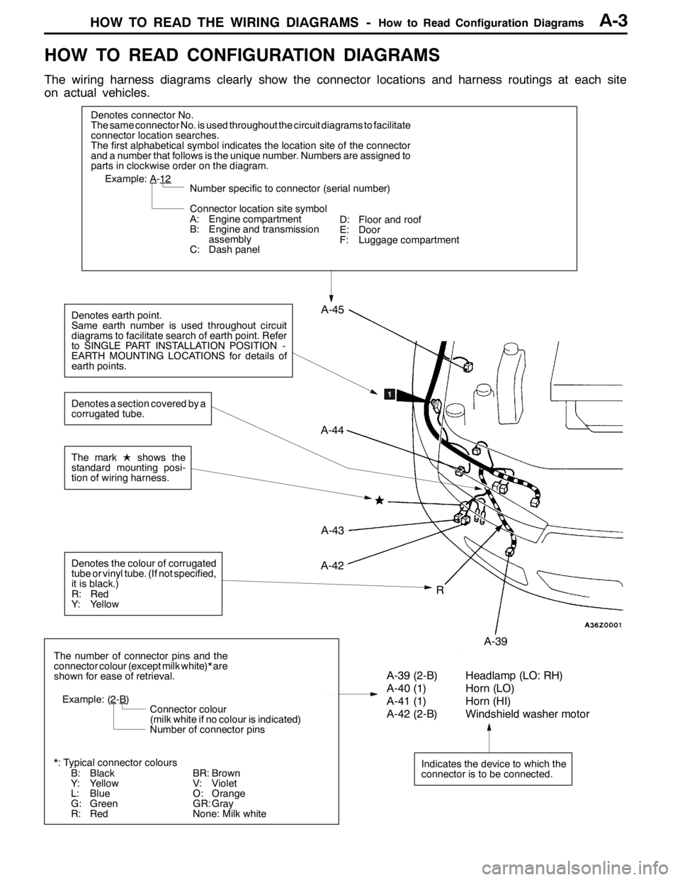
HOW TO READ CONFIGURATION DIAGRAMS
The wiring harness diagrams clearly show the connector locations and harness routings at each site
on actual vehicles.
Denotes connector No.
The same connector No. is used throughout the circuit diagrams to facilitate
connector location searches.
The first alphabetical symbol indicates the location site of the connector
and a number that follows is the unique number. Numbers are assigned to
parts in clockwise order on the diagram.
A-43
Example: A-12
Number specific to connector (serial number)
Connector location site symbol
A: Engine compartment
B: Engine and transmission
assembly
C: Dash panel
Denotes earth point.
Same earth number is used throughout circuit
diagrams to facilitate search of earth point. Refer
to SINGLE PART INSTALLATION POSITION -
EARTH MOUNTING LOCATIONS for details of
earth points.
Indicates the device to which the
connector is to be connected.
A-39 (2-B) Headlamp (LO: RH)
A-40 (1) Horn (LO)
A-41 (1) Horn (HI)
A-42 (2-B) Windshield washer motor
The number of connector pins and the
connector colour (except milk white)* are
shown for ease of retrieval.
Example: (2
-B)
Connector colour
(milk white if no colour is indicated)
Number of connector pins
*: Typical connector colours
B: Black
Y: Yellow
L: Blue
G: Green
R: Red
The markLshows the
standard mounting posi-
tion of wiring harness.
R
A-44
A-45
A-42
A-39
Denotes the colour of corrugated
tube or vinyl tube. (If not specified,
it is black.)
R: Red
Y: Yellow
Denotes a section covered by a
corrugated tube.
BR: Brown
V: Violet
O: Orange
GR: Gray
None: Milk whiteD: Floor and roof
E: Door
F: Luggage compartment
Page 99 of 1449

B-1
ELECTRICAL
WIRING
CONTENTS
WIRING HARNESS CONFIGURATION
DIAGRAMS 4.........................
OVERALL WIRING DIAGRAM
L.H. drive vehicles 4........................
R.H. drive vehicles 5........................
ENGINE COMPARTMENT
L.H. drive vehicles 6........................
R.H. drive vehicles 8........................
ENGINE AND TRANSMISSION
L.H. drive vehicles 10.......................
R.H. drive vehicles 14.......................
DASH PANEL
L.H. drive vehicles 18.......................
R.H. drive vehicles 24.......................
FLOOR AND ROOF
L.H. drive vehicles 30.......................
R.H. drive vehicles 32.......................
DOOR
L.H. drive vehicles 34.......................
R.H. drive vehicles 36.......................
LUGGAGE COMPARTMENT
L.H. drive vehicles 38.......................
R.H. drive vehicles 39.......................
SINGLE PART INSTALLATION
POSITION 40.........................
RELAY 40.................................
ECU 41...................................
SENSOR 43...............................
SOLENOID VALVE 46......................
INSPECTION CONNECTOR AND SPARE
CONNECTOR 47...........................
FUSIBLE LINK AND FUSE 48..............
EARTH CABLE 49.........................
EARTH 50.................................
CIRCUIT DIAGRAMS 54...............
J/B 54....................................
J/C
L.H. drive vehicles 56.......................
R.H. drive vehicles 62.......................
CENTRALIZED JUNCTION 68..............
POWER DISTRIBUTION SYSTEM 74........
STARTING SYSTEM 79....................
Page 108 of 1449
WIRING HARNESS CONFIGURATION DIAGRAMS
Connector
symbol
-01
thru
-37
B
B-37
B-34
B-23
B-01B-27B-26
Earth cable
B-21B-22
Connector colour code
B:Black
Y:Yellow
L:Blue
G:Green
R:Red
BR:Brown
V:Violet
O:Orange
GR:Gray
None: Milk white
B-10
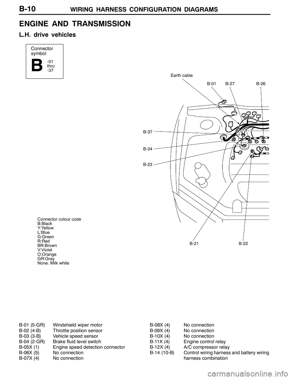
ENGINE AND TRANSMISSION
L.H. drive vehicles
B-01 (5-GR) Windshield wiper motor
B-02 (4-B) Throttle position sensor
B-03 (3-B) Vehicle speed sensor
B-04 (2-GR) Brake fluid level switch
B-05X (1) Engine speed detection connector
B-06X (5) No connection
B-07X (4) No connectionB-08X (4) No connection
B-09X (4) No connection
B-10X (4) No connection
B-11X (4) Engine control relay
B-12X (4) A/C compressor relay
B-14 (10-B) Control wiring harness and battery wiring
harness combination
Page 112 of 1449
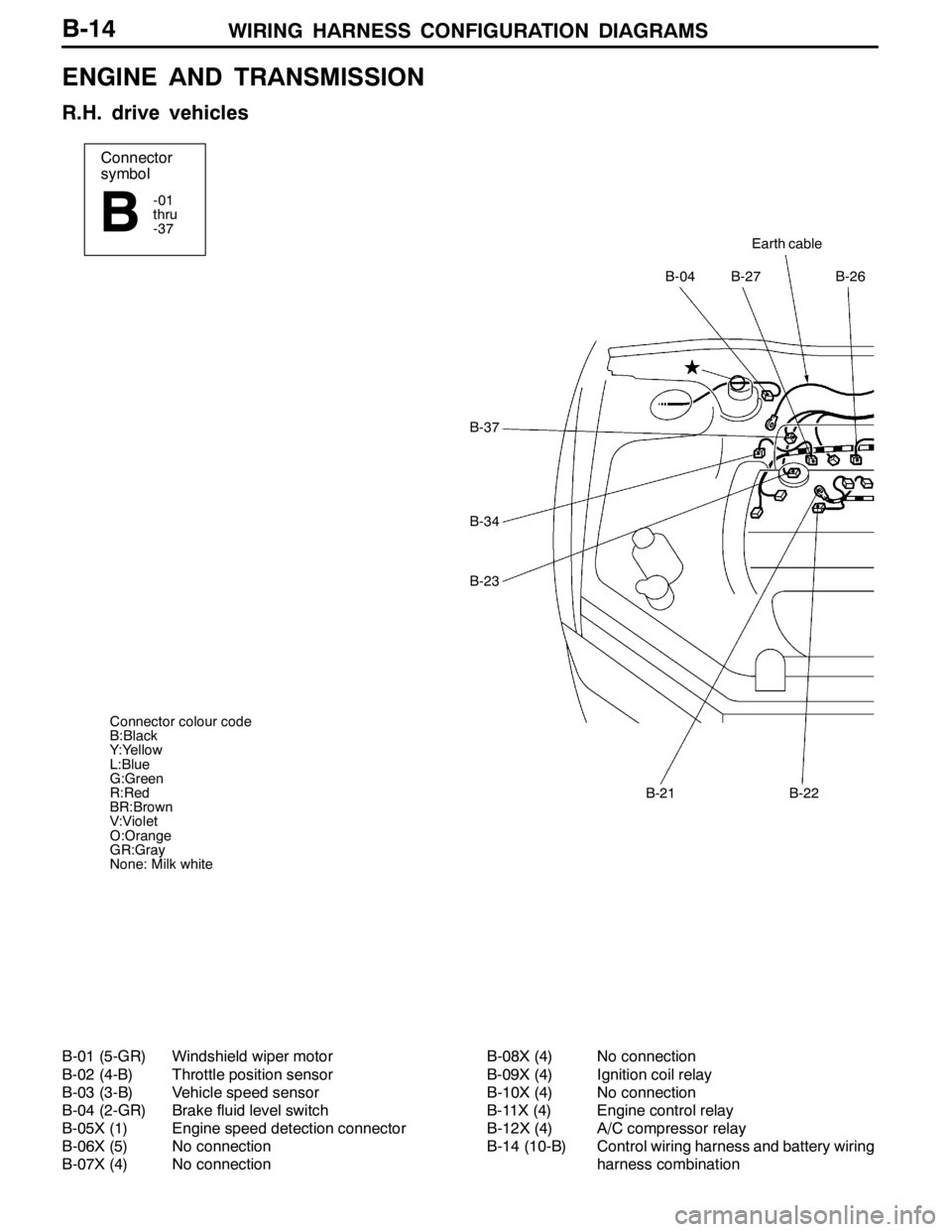
WIRING HARNESS CONFIGURATION DIAGRAMS
Connector
symbol
-01
thru
-37
B
Earth cable
B-27B-26B-04
B-22B-21
B-37
B-34
B-23
Connector colour code
B:Black
Y:Yellow
L:Blue
G:Green
R:Red
BR:Brown
V:Violet
O:Orange
GR:Gray
None: Milk white
B-14
ENGINE AND TRANSMISSION
R.H. drive vehicles
B-01 (5-GR) Windshield wiper motor
B-02 (4-B) Throttle position sensor
B-03 (3-B) Vehicle speed sensor
B-04 (2-GR) Brake fluid level switch
B-05X (1) Engine speed detection connector
B-06X (5) No connection
B-07X (4) No connectionB-08X (4) No connection
B-09X (4) Ignition coil relay
B-10X (4) No connection
B-11X (4) Engine control relay
B-12X (4) A/C compressor relay
B-14 (10-B) Control wiring harness and battery wiring
harness combination
Page 150 of 1449
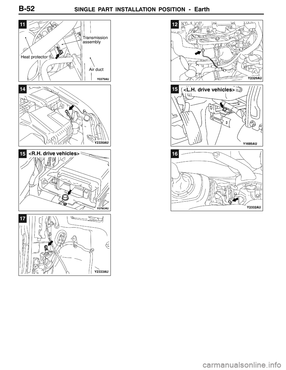
SINGLE PART INSTALLATION POSITION- Earth
11
Heat protector
Transmission
assembly
Air duct
12
1415
15
17
B-52
Page 380 of 1449

GENERAL -How to Use This Manual00-2
HOW TO USE THIS MANUAL
SCOPE OF MAINTENANCE, REPAIR
AND SERVICING EXPLANATIONS
This manual provides explanations, etc. concerning
procedures for the inspection, maintenance, repair
and servicing of the subject model. Note, however,
that for engine and transmission-related component
parts, this manual covers only on-vehicle
inspections, adjustments, and the removal and
installation procedures for major components.
For detailed information concerning the inspection,
checking, adjustment, disassembly and reassembly
of the engine, transmission and major components
after they have been removed from the vehicle,
please refer to separate manuals covering the
engine and the transmission.
ON-VEHICLE SERVICE
“On-vehicle Service” is procedures for performing
inspections and adjustments of particularly
important locations with regard to the construction
and for maintenance and servicing, but other
inspection (for looseness, play, cracking, damage,
etc.) must also be performed.
INSPECTION
Under this title are presented inspection and
checking procedures to be performed by using
special tools and measuring instruments and by
feeling, but, for actual maintenance and servicing
procedures, visual inspections should always be
performed as well.
INDICATION OF DESTINATION
General Export and GCC are used for convenience
to indicate destination.
NOTE
(1) “General Export” means territories other than
Europe, GCC, Australia, New Zealand, the
U.S.A. and Canada.
(2) “GCC” indicates countries that are members
of the (Persian) Gulf Cooperation Council of
nations.
(3) In some instances, vehicles with other
specifications may be shipped to some
countries.
DEFINITION OF TERMS
STANDARD VALUE
Indicates the value used as the standard for judging
the quality of a part or assembly on inspection
or the value to which the part or assembly is
corrected and adjusted. It is given by tolerance.
LIMIT
Shows the standard for judging the quality of a
part or assembly on inspection and means the
maximum or minimum value within which the part
or assembly must be kept functionally or in strength.
It is a value established outside the range of
standard value.
REFERENCE VALUE
Indicates the adjustment value prior to starting the
work (presented in order to facilitate assembly and
adjustment procedures, and so they can be
completed in a shorter time).
CAUTION
Indicates the presentation of information particularly
vital to the worker during the performance of
maintenance and servicing procedures in order to
avoid the possibility of injury to the worker, or
damage to component parts, or a reduction of
component or vehicle function or performance, etc.
INDICATION OF TIGHTENING TORQUE
Tightening torques (units: N·m) are set to take into
account the central value and the allowable
tolerance. The central value is the target value,
and the allowable tolerance provides the checking
range for tightening torques. If bolts and nuts are
not provided with tightening torques, refer to
P.00-28.
Page 381 of 1449

GENERAL -How to Use This Manual00-3
MODEL INDICATIONS
The following abbreviations are used in this manual for classification of model types.
MPI: Indicates the multipoint injection, or engine equipped with the multipoint injection.
DOHC: Indicates an engine with the double overhead camshaft, or a model equipped with such an
engine.
M/T: Indicates the manual transmission, or models equipped with the manual transmission.
A/C: Indicates the air conditioner.