wheel alignment MITSUBISHI LANCER EVOLUTION 2007 Service Repair Manual
[x] Cancel search | Manufacturer: MITSUBISHI, Model Year: 2007, Model line: LANCER EVOLUTION, Model: MITSUBISHI LANCER EVOLUTION 2007Pages: 1449, PDF Size: 56.82 MB
Page 813 of 1449
MANUAL TRANSMISSION - Troubleshooting
TROUBLESHOOTING
BASIC TROUBLESHOOTING CONDITIONS
Refer to GROUP 00 - How to Use Troubleshooting/Inspection Service Points.
NOTE
Before starting the troubleshooting procedure, make sure that the following items have been checked
okay.
DIs the appropriate steering wheel installed at the center of the steering column shaft correctly?
DAre the tire, wheel size, specifications, air pressure, balance, and wear state normal?
DIs the wheel alignment normal?
DHas the engine, suspension, etc. been remodeled in such a way that it will affect the ACD and AYC
systems?
DIAGNOSIS FUNCTION
READING DIAGNOSIS CODE
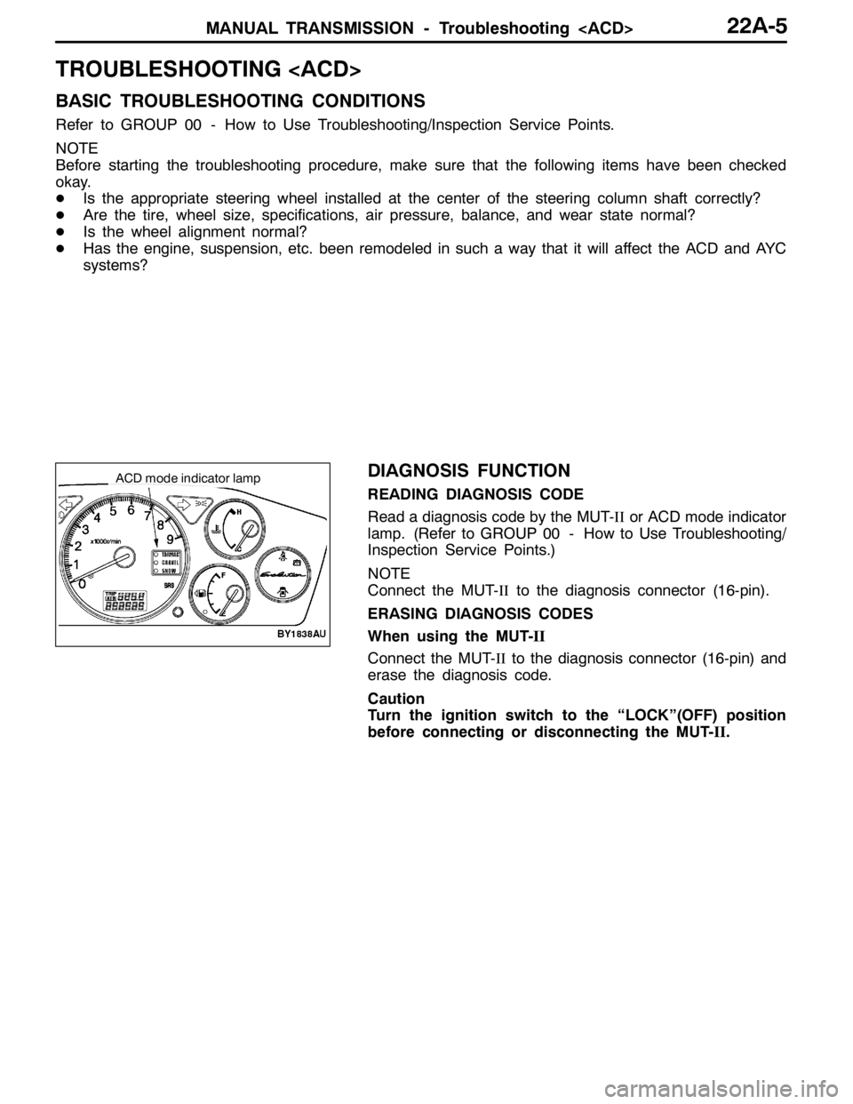
Read a diagnosis code by the MUT-IIor ACD mode indicator
lamp. (Refer to GROUP 00 - How to Use Troubleshooting/
Inspection Service Points.)
NOTE
Connect the MUT-IIto the diagnosis connector (16-pin).
ERASING DIAGNOSIS CODES
When using the MUT-II
Connect the MUT-IIto the diagnosis connector (16-pin) and
erase the diagnosis code.
Caution
Turn the ignition switch to the “LOCK”(OFF) position
before connecting or disconnecting the MUT-II.
ACDmode indicator lamp
Page 954 of 1449

REAR AXLE -Special Tools/Troubleshooting
NumberNameO.D.mm
BoxMB990551Box–
CBaseMB990989Base–
ABCBase
MB990990Tool A25A
Tool
MB990991Tool B28
ToolMB990992Tool C31
Installer adapterBrass bar
Bar (one-touch type) AB
C
Toolbox
Tool numberO.D.mmTool numberO.D.mm
AMB99092639AMB99093363.5
MB99092745MB99093467.5
MB99092849.5MB99093571.5
MB99092951MB99093675.5
MB99093054MB99093779
MB99093157BMB990938-
MB99093261CMB990939-
TROUBLESHOOTING
BASIC TROUBLESHOOTING CONDITIONS
Refer to GROUP 00 – How to Use Troubleshooting/Inspection Service Points.
NOTE
Before starting the troubleshooting procedure, make sure that the following items have been checked
okay.
DThe correct steering wheel has been properly installed in the neutral position of the steering column
shaft.
DTire and wheel sizes are correct with correct specifications. Inflation pressure, balance, and wear
conditions are okay.
DWheel alignment is correct.
DThe engine, suspension, and other parts have not been remodeled so as to affect the AYC system.
DIAGNOSIS FUNCTION
READING THE DIAGNOSIS CODES
Read the diagnosis code using MUT-IIor ACD mode indicator
lamp. (Refer to GROUP 00 – How to Use Troubleshooting/
Inspection Service Points.)
NOTE
Connect the MUT-IIto the 16-pin diagnosis connector.
Page 969 of 1449
REAR AXLE -On-vehicle Service27B-23
3. If the limit value is exceeded, loosen the flange nut and
then tighten it to the specified torque 225±25 N·m and
check the rear hub rotary sliding resistance again.
4. Replace the rear hub assembly if an adjustment cannot
be made to within the limit.
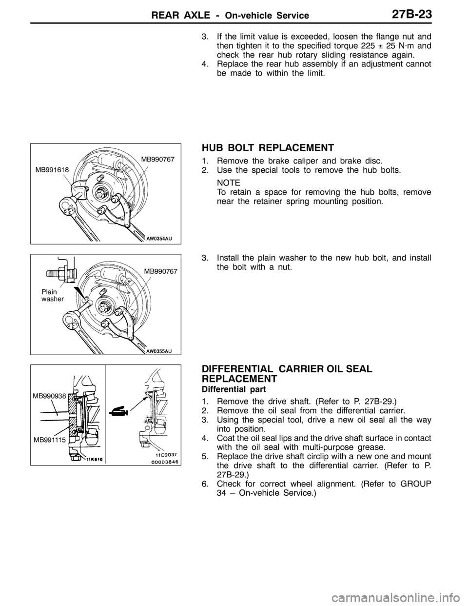
HUB BOLT REPLACEMENT
1. Remove the brake caliper and brake disc.
2. Use the special tools to remove the hub bolts.
NOTE
To retain a space for removing the hub bolts, remove
near the retainer spring mounting position.
3. Install the plain washer to the new hub bolt, and install
the bolt with a nut.
DIFFERENTIAL CARRIER OIL SEAL
REPLACEMENT
Differential part
1. Remove the drive shaft. (Refer to P. 27B-29.)
2. Remove the oil seal from the differential carrier.
3. Using the special tool, drive a new oil seal all the way
into position.
4. Coat the oil seal lips and the drive shaft surface in contact
with the oil seal with multi-purpose grease.
5. Replace the drive shaft circlip with a new one and mount
the drive shaft to the differential carrier. (Refer to P.
27B-29.)
6. Check for correct wheel alignment. (Refer to GROUP
34 – On-vehicle Service.)
MB991618MB990767
Plain
washerMB990767
MB990938
MB991115
Page 970 of 1449
REAR AXLE -On-vehicle Service27B-24
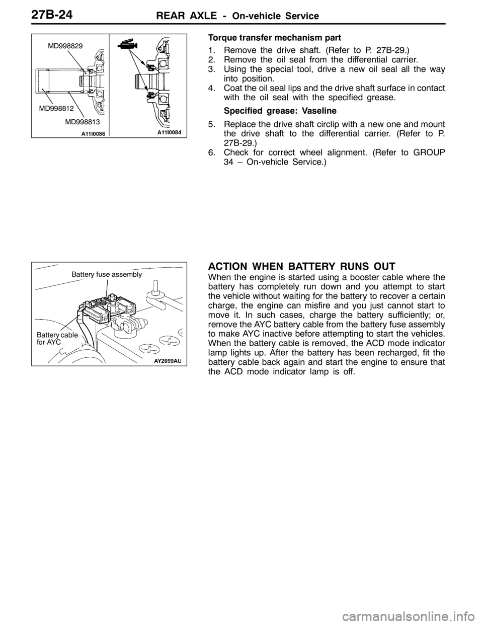
Torque transfer mechanism part
1. Remove the drive shaft. (Refer to P. 27B-29.)
2. Remove the oil seal from the differential carrier.
3. Using the special tool, drive a new oil seal all the way
into position.
4. Coat the oil seal lips and the drive shaft surface in contact
with the oil seal with the specified grease.
Specified grease: Vaseline
5. Replace the drive shaft circlip with a new one and mount
the drive shaft to the differential carrier. (Refer to P.
27B-29.)
6. Check for correct wheel alignment. (Refer to GROUP
34 – On-vehicle Service.)
ACTION WHEN BATTERY RUNS OUT
When the engine is started using a booster cable where the
battery has completely run down and you attempt to start
the vehicle without waiting for the battery to recover a certain
charge, the engine can misfire and you just cannot start to
move it. In such cases, charge the battery sufficiently; or,
remove the AYC battery cable from the battery fuse assembly
to make AYC inactive before attempting to start the vehicles.
When the battery cable is removed, the ACD mode indicator
lamp lights up. After the battery has been recharged, fit the
battery cable back again and start the engine to ensure that
the ACD mode indicator lamp is off.
MD998829
MD998813 MD998812
Battery fuse assembly
Battery cable
for AYC
Page 975 of 1449
REAR AXLE -Drive Shaft27B-29
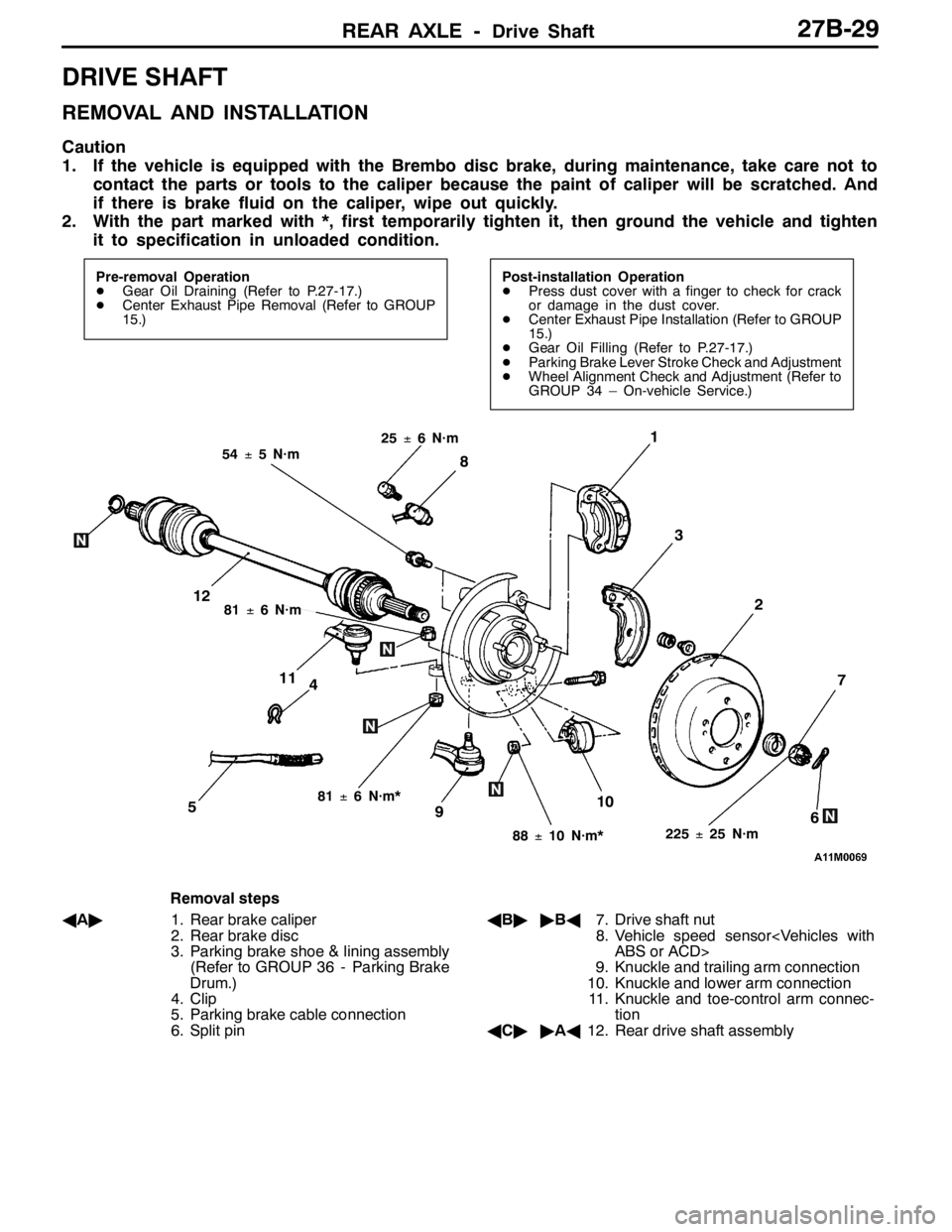
DRIVE SHAFT
REMOVAL AND INSTALLATION
Caution
1. If the vehicle is equipped with the Brembo disc brake, during maintenance, take care not to
contact the parts or tools to the caliper because the paint of caliper will be scratched. And
if there is brake fluid on the caliper, wipe out quickly.
2. With the part marked with *, first temporarily tighten it, then ground the vehicle and tighten
it to specification in unloaded condition.
Pre-removal Operation
DGear Oil Draining (Refer to P.27-17.)
DCenter Exhaust Pipe Removal (Refer to GROUP
15.)Post-installation Operation
DPress dust cover with a finger to check for crack
or damage in the dust cover.
DCenter Exhaust Pipe Installation (Refer to GROUP
15.)
DGear Oil Filling (Refer to P.27-17.)
DParking Brake Lever Stroke Check and Adjustment
DWheel Alignment Check and Adjustment (Refer to
GROUP 34 – On-vehicle Service.)
4
1
3
7
6510
2
8
9
11
12
225±25 N·m
54±5 N·m
88±10 N·m*
81±6 N·m*
81±6 N·m
25±6 N·m
Removal steps
AA"1. Rear brake caliper
2. Rear brake disc
3. Parking brake shoe & lining assembly
(Refer to GROUP 36 - Parking Brake
Drum.)
4. Clip
5. Parking brake cable connection
6. Split pinAB""BA7. Drive shaft nut
8. Vehicle speed sensor
9. Knuckle and trailing arm connection
10. Knuckle and lower arm connection
11. Knuckle and toe-control arm connec-
tion
AC""AA12. Rear drive shaft assembly
Page 1011 of 1449

WHEEL AND TYRE -Troubleshooting31-3
TROUBLESHOOTING
SymptomProbable causeRemedyReference page
Rapid wear at
shouldersUnder-inflation
or lack of rotationAdjust the tyre
pressure.31-6
Rapid wear at
centreOver-inflation or
lack of rotation
Cracked treadsUnder-inflationAdjust the tyre
pressure.31-6
Wear on one
sideExcessive
camberInspect the
camber.Refer to
GROUP 33A -
On-vehicle
Service.
Feathered edgeIncorrect toe-inAdjust the toe-in.
Bald spotsUnbalanced
wheelAdjust the
imbalanced
wheels.31-4
Scalloped wearLack of rotation of tyres or worn or
out-of-alignment suspensionRotate the tyres
and check the
front suspension
alignment.Refer to
GROUP 33A -
On-vehicle
Service.
Page 1022 of 1449

POWER PLANT MOUNT - Crossmember32-8
CROSSMEMBER
REMOVAL AND INSTALLATION
Caution
1. Before removing the steering wheel and air bag module assembly, always refer to GROUP
52B - Service Precautions, Air bag Module and Clock Spring. Also, set the front wheels so
that they are facing straight forward, and remove the ignition key. If you fail to do this, the
SRS clock spring will be damaged, causing the SRS air bag to be inoperative and serious
injury.
2. *
1: Indicates parts which should be initially tightened, and then fully tightened after placing
the vehicle horizontally and loading the full weight of the engine on the vehicle body.
3. *
2: Indicates parts which should be temporarily tightened, and then fully tightened with the
vehicle on the ground in the unladen condition.
Caution
If the vehicle is equipped the Brembo disc brake, during maintenance, take care not to contact
the parts or tools to the caliper because the paint of caliper will be scratched.
Pre-removal Operations
DUnder Cover Removal
(Refer to GROUP 51 - Front Bumper.)
DCentermember, Crossmember Bar Removal
(Refer to P.32-6.)
DFront Exhaust Pipe Removal
(Refer to GROUP 15.)
DSteering Wheel Air Bag Module Assembly Removal
(Refer to GROUP 37A.)
DPower Steering Fluid Draining
(Refer to GROUP 37A - On-vehicle Service.)Post-installation Operations
DCentermember, Crossmember Bar Installation
(Refer to P.32-6.)
DFront Exhaust Pipe Installation
(Refer to GROUP 15.)
DSteering Wheel Air Bag Module Assembly
Installation (Refer to GROUP 37A.)
DPower Steering Fluid Supplying
(Refer to GROUP 37A - On-vehicle Service.)
DPower Steering Fluid Line Bleeding
(Refer to GROUP 37A - On-vehicle Service.)
DPress the dust cover with a finger to check whether
the dust cover is cracked or damaged.
DChecking Steering Wheel Position with Wheels
Straight Ahead
DFront Wheel Alignment Check and Adjustment
(Refer to GROUP 37A - On-vehicle Service.)
DUnder Cover Installation
(Refer to GROUP 51 - Front Bumper.)
Page 1027 of 1449

33A-1
FRONT
SUSPENSION
CONTENTS
GENERAL INFORMATION 2..................
SERVICE SPECIFICATIONS 3.................
SPECIAL TOOLS 3...........................
ON-VEHICLE SERVICE 4.....................
Wheel Alignment Check and Adjustment 4.......Ball Joint Dust Cover Check 5..................
STRUT ASSEMBLY 6.........................
LOWER ARM ASSEMBLY 9..................
STABILIZER BAR 12.........................
CROSSMEMBER BAR 15.....................
Page 1030 of 1449
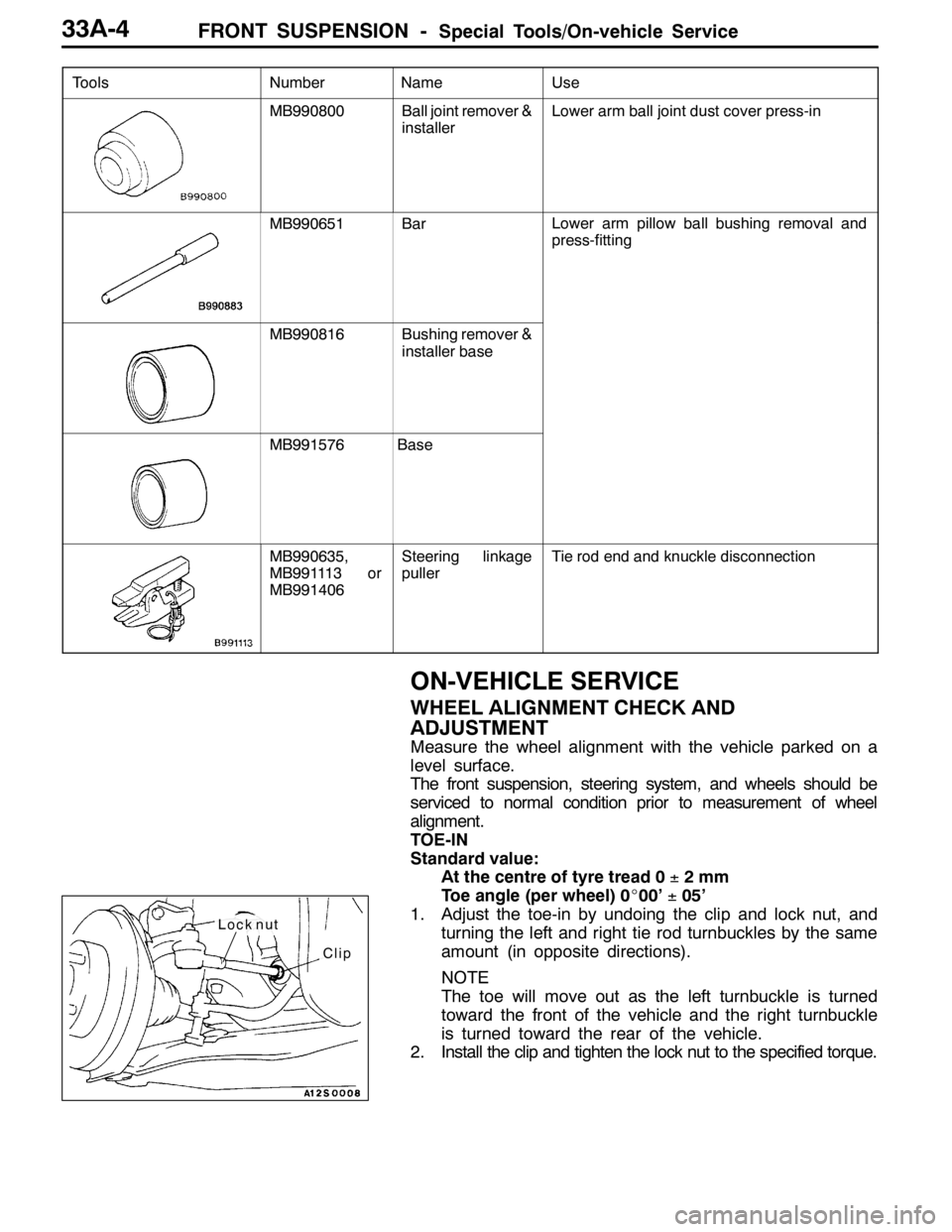
FRONT SUSPENSION -Special Tools/On-vehicle Service33A-4
Tools UseName Number
MB990800Ball joint remover &
installerLower arm ball joint dust cover press-in
MB990651BarLower arm pillow ball bushing removal and
press-fitting
MB990816Bushing remover &
installer base
MB991576Base
MB990635,
MB991113 or
MB991406Steering linkage
pullerTie rod end and knuckle disconnection
ON-VEHICLE SERVICE
WHEEL ALIGNMENT CHECK AND
ADJUSTMENT
Measure the wheel alignment with the vehicle parked on a
level surface.
The front suspension, steering system, and wheels should be
serviced to normal condition prior to measurement of wheel
alignment.
TOE-IN
Standard value:
At the centre of tyre tread 0±2mm
Toe angle (per wheel) 0_00’±05’
1. Adjust the toe-in by undoing the clip and lock nut, and
turning the left and right tie rod turnbuckles by the same
amount (in opposite directions).
NOTE
The toe will move out as the left turnbuckle is turned
toward the front of the vehicle and the right turnbuckle
is turned toward the rear of the vehicle.
2. Install the clip and tighten the lock nut to the specified torque.
Clip
Lock nut
Page 1031 of 1449
FRONT SUSPENSION -On-vehicle Service33A-5
Tightening torque: 52±2 N·m
3. Confirm that the toe-in is at the standard value.
4. Use a turning radius gauge to check that the steering
angle is at the standard value.
Standard value:
Inner wheels31_45’±1_30’
Outer wheels (for reference)27_15’
TOE-OUT ANGLE ON TURNS
To check the steering linkage, especially after the vehicle
has been involved in an accident or if an accident is presumed,
it is advisable to check the toe-out angle on turns in addition
to the wheel alignment.
Conduct this test on the left turn as well as on the right turn.
Standard value:
ItemsSpecifications
Toe-out angle on turns
(inner wheel when outer wheel at 20_)22_00’±1_30’
CAMBER, CASTER AND KINGPIN INCLINATION
Standard value:
ItemsSpecifications
Camber
(Selectable from 2 options)-1_00’±30’* or - 2_00’±30’*
Caster3_55’±30’*
Kingpin inclination13_45’±1_30’
NOTE
1. *: difference between right and left wheels must be less
than 30’
2. Caster and kingpin inclination are preset at the factory
and cannot be adjusted.
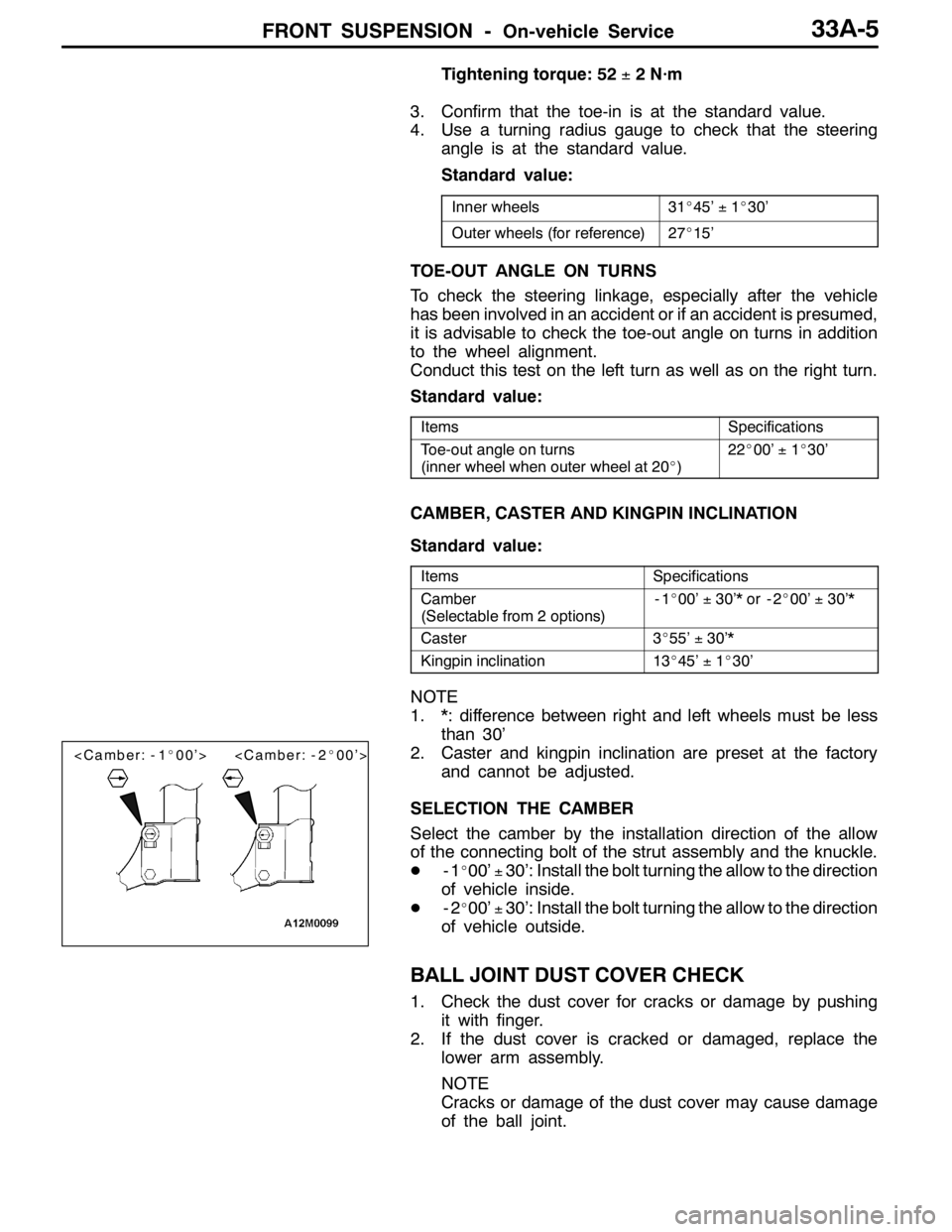
SELECTION THE CAMBER
Select the camber by the installation direction of the allow
of the connecting bolt of the strut assembly and the knuckle.
D-1
_00’±30’: Install the bolt turning the allow to the direction
of vehicle inside.
D-2
_00’±30’: Install the bolt turning the allow to the direction
of vehicle outside.
BALL JOINT DUST COVER CHECK
1. Check the dust cover for cracks or damage by pushing
it with finger.
2. If the dust cover is cracked or damaged, replace the
lower arm assembly.
NOTE
Cracks or damage of the dust cover may cause damage
of the ball joint.