ESP MITSUBISHI LANCER EVOLUTION 2014 10.G User Guide
[x] Cancel search | Manufacturer: MITSUBISHI, Model Year: 2014, Model line: LANCER EVOLUTION, Model: MITSUBISHI LANCER EVOLUTION 2014 10.GPages: 338, PDF Size: 40.99 MB
Page 95 of 338
Door locks 5-34 Features and controls
5
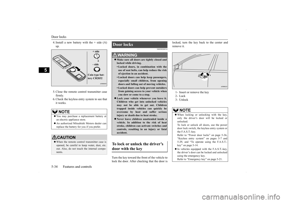
4. Install a new battery with the + side (A) up. 5. Close the remote control transmitter case firmly. 6. Check the keyless entry system to see thatit works.
N00509200518
Turn the key toward the front of the vehicle tolock the door. After checking that the door is
locked, turn the key back to the center and remove it.
NOTE
You may purchase a replacement battery at an electric appliance store. An authorized Mitsubishi Motors dealer can replace the battery for you if you prefer.CAUTION When the remote control transmitter case is opened, be careful to keep water, dust, etc. out. Also, do not touch the internal compo- nents.
+ side - side
Coin type bat- tery CR2032
Door locks
WA R N I N G Make sure all doors are tightly closed and locked while driving.• Locked doors, in combination with theuse of seat belts, can help reduce the risk of ejection in an accident.• Locked doors can help keep passengers,especially small children, from opening doors and falling out of moving vehicles.• Locked doors can help prevent outsidersfrom gaining access to your vehicle whenyou slow or come to a stop.
Lock your vehicle whenever you leave it. Children who get into unlocked vehicles may not be able to get out. Children trapped inside vehicles can quickly beovercome by heat and suffer serious injury or death due to heat stroke. Never leave children unattended inside a vehicle. In addition to the risk of heat stroke, children can activate switches andcontrols, resulting in an injury or fatal accident.
To lock or unlock the driver’s door with the key
1- Insert or remove the key 2- Lock 3- Unlock
NOTE
When locking or unlocking with the key, only the driver’s door will be locked or unlocked.To lock or unlock all doors, use the power door lock switch, the keyless entry system or the F.A.S.T.-key.Refer to “Power door locks” on page 5-36, “Keyless entry system” on pages 5-7 and 5-29, and “To operate using the F.A.S.T.-key” on page 5-14. In vehicles equipped with the F.A.S.T.-key, the driver’s door can be locked and unlocked using the emergency key. Refer to “Emergency key” on page 5-21.
BK0200800US.bo
ok 34 ページ 2013年2月14日 木曜日 午後2時28分
Page 98 of 338
“Child safety locks” for rear door
Features and controls 5-37
5
N00509400233
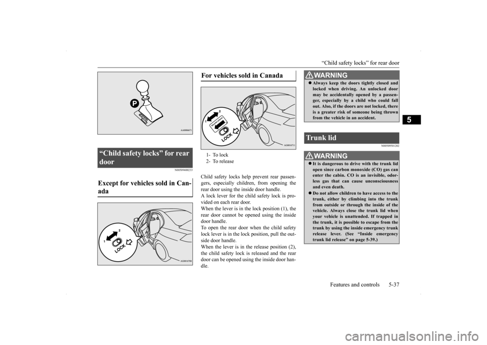
Child safety locks help prevent rear passen- gers, especially children, from opening therear door using the inside door handle. A lock lever for the child safety lock is pro- vided on each rear door.When the lever is in the lock position (1), the rear door cannot be
opened using the inside
door handle.To open the rear door when the child safety lock lever is in the lock position, pull the out- side door handle.When the lever is in th
e release position (2),
the child safety lock is released and the rear door can be opened using the inside door han-dle.
N00509501202
“Child safety locks” for rear door Except for vehicles sold in Can- ada
For vehicles sold in Canada 1- To lock 2- To release
WA R N I N G Always keep the doors tightly closed and locked when driving. An unlocked door may be accidentally opened by a passen- ger, especially by a child who could fall out. Also, if the doors are not locked, thereis a greater risk of someone being thrown from the vehicle in an accident.
Trunk lid
WA R N I N G It is dangerous to drive with the trunk lid open since carbon monoxide (CO) gas can enter the cabin. CO is an invisible, odor- less gas that can cause unconsciousnessand even death. Do not allow children to have access to the trunk, either by climbing into the trunk from outside or through the inside of the vehicle. Always clos
e the trunk lid when
your vehicle is unattended. If trapped in the trunk, it is possible to escape from the trunk by using the inside emergency trunk release lever. (See “Inside emergency trunk lid release” on page 5-39.)
BK0200800US.bo
ok 37 ページ 2013年2月14日 木曜日 午後2時28分
Page 100 of 338
Inside emergency trunk lid release
Features and controls 5-39
5
N00509800178
The emergency trunk lid release is designed to provide a way to open the trunk lid from inside the trunk. It was developed to help pre- vent death and serious injuries to childrenwho might become locked inside a vehicle trunk.
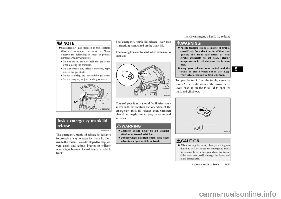
The emergency trunk lid release lever (see illustration) is mounted on the trunk lid. The lever glows in the dark after exposure to sunlight. You and your family should familiarize your- selves with the location and operation of the emergency trunk lid release lever. Childrenshould be taught not to play in or aroundvehicles.
To open the trunk from the inside, move the lever (A) in the direction of the arrow on thelever. Push up on the trunk lid to open the trunk and climb out.
NOTE
Gas struts (A) are installed in the locations illustrated to support the trunk lid. Please observe the following in order to prevent damage or faulty operation. • Do not touch, push or pull the gas struts when closing the trunk lid. • Do not attach any plastic material, tape, etc., to the gas struts. • Do not tie string, etc., around the gas struts. • Do not hang any object on the gas struts.
Inside emergency trunk lid release
WA R N I N G Children should never be left unsuper- vised in or around vehicles. Unsupervised children could lock them- selves in an open vehicle or trunk.
People trapped inside a vehicle or trunk, even if only for a short period of time, can quickly die from suffocation or heat stroke, especially on hot days. Interior temperatures in vehicles can rise in min-utes. Keep your vehicle doors locked and the trunk lid closed when not in use. Keep your vehicle keys away from children.CAUTION When loading the trunk, place your things so that they will not touch the emergency trunk lid release lever when you close the trunk. Otherwise you could damage the lever and make it unusable.WA R N I N G
BK0200800US.bo
ok 39 ページ 2013年2月14日 木曜日 午後2時28分
Page 103 of 338
Power windows 5-42 Features and controls
5
Use the following procedure to test the sys- tem: 1. Lower the driver’s window.
2. Arm the system as explained in “Armed stage”. 3. Make sure that the theft-alarm indicator comes on and flashes for approximately20 seconds. 4. Wait a few seconds and then unlock the driver’s side door by using the inside doorlock knob and open the door. 5. Check to be sure that the horn sounds intermittently and the headlights blink onand off when the door is opened.6. Disarm the system by unlocking all doors by the keyless entry system or the F.A.S.T.-key operation.
N00510800266
N00548700114
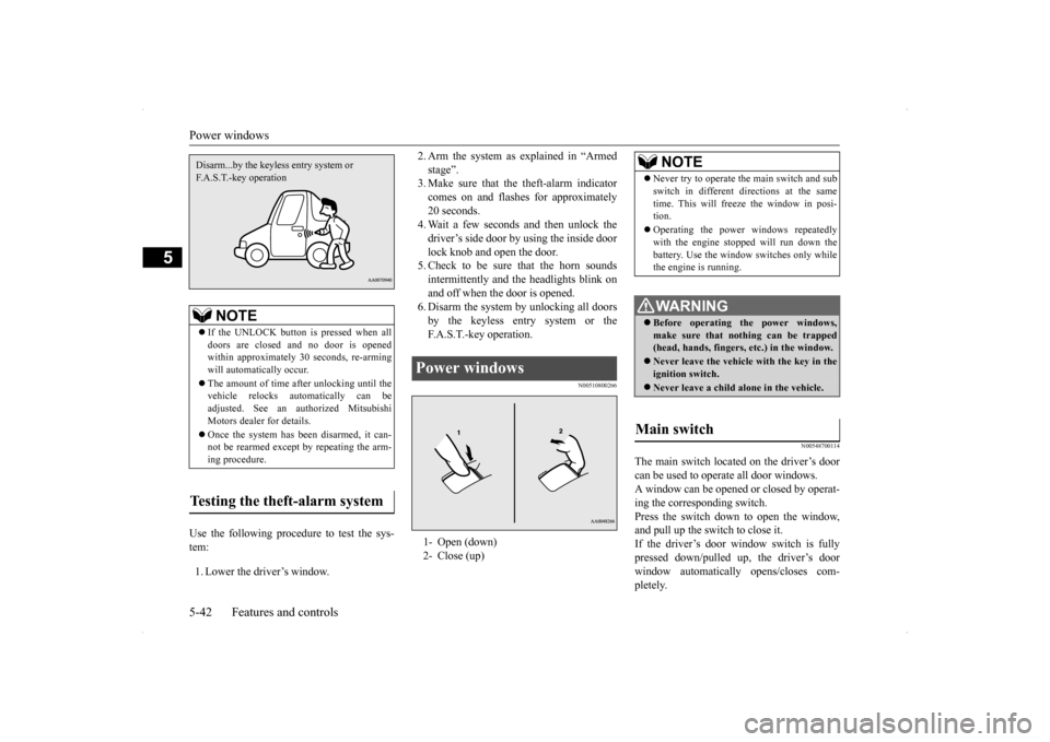
The main switch located on the driver’s door can be used to operate all door windows. A window can be opened or closed by operat- ing the corresponding switch.Press the switch down to open the window, and pull up the switch to close it. If the driver’s door window switch is fullypressed down/pulled up, the driver’s door window automatically opens/closes com- pletely.
NOTE
If the UNLOCK button is pressed when all doors are closed and no door is opened within approximately 30 seconds, re-armingwill automatically occur. The amount of time after unlocking until the vehicle relocks automatically can be adjusted. See an authorized Mitsubishi Motors dealer for details. Once the system has been disarmed, it can- not be rearmed except by repeating the arm-ing procedure.
Testing the theft-alarm system Disarm...by the keyless entry system or F.A.S.T.-key operation
Power windows 1- Open (down) 2- Close (up)
NOTE
Never try to operate the main switch and sub switch in different directions at the same time. This will freeze the window in posi- tion. Operating the power windows repeatedly with the engine stopped will run down the battery. Use the window switches only whilethe engine is running. WA R N I N G Before operating the power windows, make sure that nothing can be trapped(head, hands, fingers, etc.) in the window. Never leave the vehicle with the key in the ignition switch. Never leave a child alone in the vehicle.
Main switch
BK0200800US.bo
ok 42 ページ 2013年2月14日 木曜日 午後2時28分
Page 104 of 338
Power windows
Features and controls 5-43
5
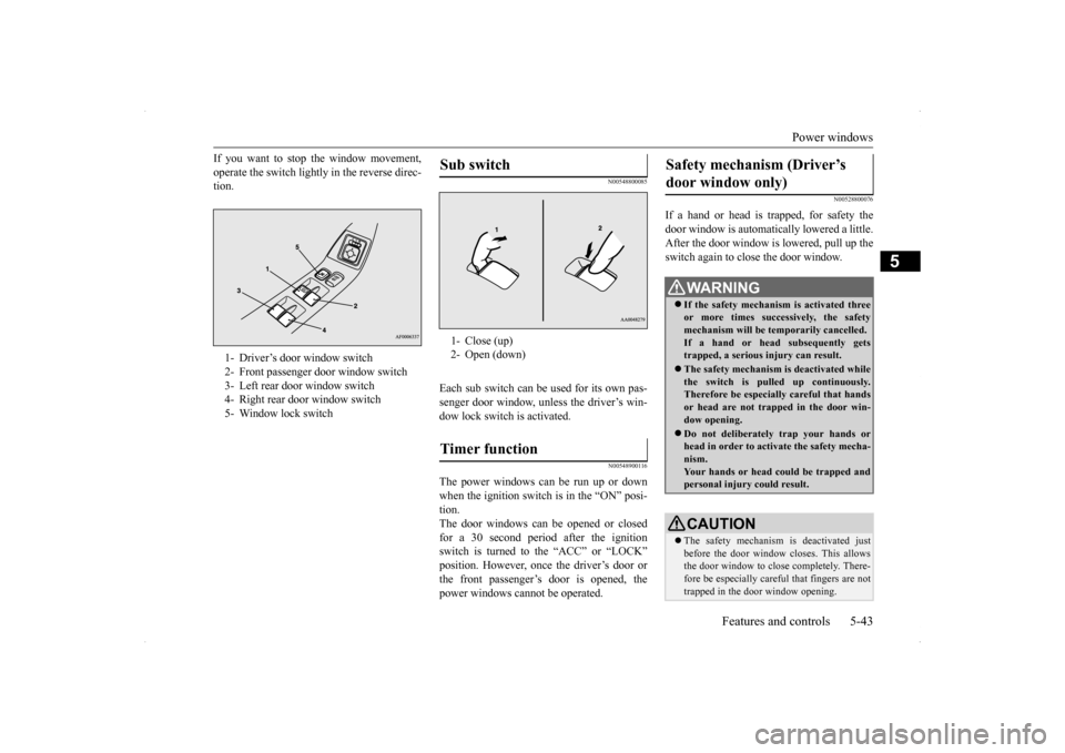
If you want to stop the window movement, operate the switch lightly in the reverse direc- tion.
N00548800085
Each sub switch can be used for its own pas-senger door window, unless the driver’s win- dow lock switch is activated.
N00548900116
The power windows can be run up or down when the ignition switch is in the “ON” posi- tion.The door windows can be opened or closed for a 30 second period after the ignition switch is turned to the “ACC” or “LOCK”position. However, once the driver’s door or the front passenger’s door is opened, the power windows cannot be operated.
N00528800076
If a hand or head is trapped, for safety thedoor window is automatically lowered a little. After the door window is lowered, pull up the switch again to close the door window.
1- Driver’s door window switch 2- Front passenger door window switch3- Left rear door window switch 4- Right rear door window switch 5- Window lock switch
Sub switch 1- Close (up) 2- Open (down)Timer function
Safety mechanism (Driver’s door window only)
WA R N I N G If the safety mechanism is activated three or more times successively, the safetymechanism will be temporarily cancelled. If a hand or head subsequently gets trapped, a serious injury can result. The safety mechanism is deactivated while the switch is pulled up continuously.Therefore be especially careful that hands or head are not trapped in the door win- dow opening. Do not deliberately trap your hands or head in order to activate the safety mecha-nism. Your hands or head could be trapped and personal injury could result.CAUTION The safety mechanism is deactivated just before the door window closes. This allowsthe door window to close completely. There- fore be especially careful that fingers are not trapped in the door window opening.
BK0200800US.bo
ok 43 ページ 2013年2月14日 木曜日 午後2時28分
Page 106 of 338
Sunroof (if so equipped)
Features and controls 5-45
5
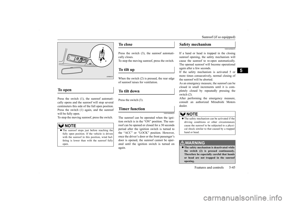
Press the switch (1), the sunroof automati- cally opens and the sunroof will stop several centimeters this side of the full open position. Press the switch (1) again, and the sunroofwill be fully open.To stop the moving sunroo
f, press the switch.
Press the switch (3), the sunroof automati- cally closes.To stop the moving sunroof, press the switch. When the switch (2) is pressed, the rear edge of sunroof raises for ventilation. Press the switch (3).
N00544800029
The sunroof can be oper
ated when the igni-
tion switch is in the “ON” position. The sun- roof can be opened or closed for a 30 secondsperiod after the ignition
switch is turned to
the “ACC” or “LOCK” position. However, once the driver’s door or the front passenger’sdoor is opened, the sunroof cannot be oper- ated until the ignition switch is turned on again.
N00544900059
If a hand or head is trapped in the closingsunroof opening, the safety mechanism willcause the sunroof to re-open automatically. The opened sunroof will become operational again after a few seconds.If the safety mechanism is activated 5 or more times consecutively, normal closing of the sunroof will be aborted.As an emergency measure, the sunroof can beclosed in small increments until it is com- pletely closed by repeatedly pressing the switch (2).After performing the emergency measure, consult an authorized Mitsubishi Motors dealer.
To open
NOTE
The sunroof stops just before reaching the fully open position. If the vehicle is driven with the sunroof in this position, wind buf- feting is lower than with the sunroof fullyopen.
To close
To tilt up
To tilt down
Timer function
Safety mechanism
NOTE
The safety mechanism can be activated if the driving conditions or other circumstances cause the sunroof to be subjected to a physi-cal shock similar to that caused by a trapped hand or head.WA R N I N G The safety mechanism is deactivated while the switch (2) is pressed continuously. Therefore be especially careful that handsor head are not trapped in the sunroof opening.
BK0200800US.bo
ok 45 ページ 2013年2月14日 木曜日 午後2時28分
Page 107 of 338
Sunroof (if so equipped) 5-46 Features and controls
5
N00545000028
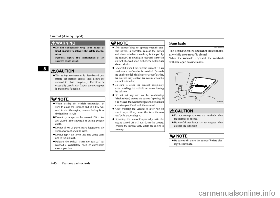
The sunshade can be opened or closed manu- ally while the sunroof is closed.When the sunroof is opened, the sunshade will also open automatically.
Do not deliberately trap your hands or head in order to activate the safety mecha- nism. Personal injury and malfunction of the sunroof could result.CAUTION The safety mechanism is deactivated just before the sunroof closes. This allows the sunroof to close completely. Therefore be especially careful that fingers are not trappedin the sunroof opening.NOTE
When leaving the vehicle unattended, be sure to close the sunroof and if a key wasused to start the engine, remove the key from the ignition switch. Do not try to operate the sunroof if it is fro- zen closed (after snowfall or during extreme cold). Do not sit on or place heavy luggage on the sunroof or roof opening edge. Do not apply any force that may cause dam- age to the sunroof. Release the switch when the sunroof has reached a completely open or completely closed position.WA R N I N G
If the sunroof does not operate when the sun- roof switch is operated, release the switch and check whether some
thing is trapped by
the sunroof. If nothing is trapped, have the sunroof checked at an authorized MitsubishiMotors dealer. Be careful when tilting
up the sunroof if a ski
carrier or a roof carrier is installed. Depend- ing on the model of ski car
rier or roof carrier,
the sunroof may contact the carrier when thesunroof is tilted up. Be sure to close the sunroof completely when washing the vehicle or when leaving the vehicle. Do not put any wax on the weatherstrip (black rubber) around the sunroof opening. If it is waxed, the weatherstrip cannot maintaina weatherproof seal with the sunroof. After washing the vehicle or after rain be sure to wipe off any water that is on the sun- roof before operating it. Operating the sunroof repeatedly with the engine turned off will run down the battery. Operate the sunroof only while the engine isrunning.NOTE
Sunshade
CAUTION Do not attempt to close the sunshade when the sunroof is opened. Be careful that hands are not trapped when closing the sunshade.NOTE
Be sure to tilt down the sunroof before clos- ing the sunshade.
BK0200800US.bo
ok 46 ページ 2013年2月14日 木曜日 午後2時28分
Page 119 of 338
Twin Clutch SST (Sportronic Shif
t Transmission) (if so equipped)
5-58 Features and controls
5
N00513100156
The table below shows the maximum rec- ommended driving speed for in each gear.Do not drive near or at these speeds forprolonged periods of time. Do not use the gearshift lever as a han- drest. This can result in premature wear of the transaxle shift forks.
N00539700017
The Twin Clutch SST is a transmission that, through integrated control of the engine and transmission, is able to achieve both the smooth shifting of an automatic transaxle andthe acceleration and fuel economy close to amanual transaxle. In addition, the control mode can be selected from three types to suit the driving conditions.Together with manual shifting, the transmis- sion is capable of responding to a variety of driving circumstances. Twin Clutch SST control mode
P.5-62
Manual shift
P.5-64
N00539800063
As an additional safety precaution, models equipped with a Twin Clutch SST have a shift-lock device that holds the gearshift lever in the “P” (PARK) position. To move thegearshift lever from the “P” (PARK) position to another position, follow the steps below. 1. Press and hold the brake pedal down.
2. Move the gearshift lever to the desired position.
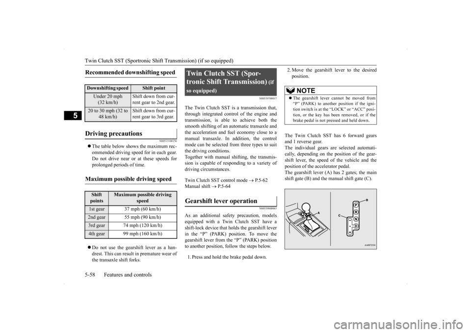
The Twin Clutch SST has 6 forward gears and 1 reverse gear.The individual gears are selected automati- cally, depending on the position of the gear- shift lever, the speed of the vehicle and theposition of the accelerator pedal. The gearshift lever (A) has 2 gates; the main shift gate (B) and the manual shift gate (C).
Recommended downshifting speed
Downshifting speed
Shift point
Under 20 mph (32 km/h)
Shift down from cur- rent gear to 2nd gear.
20 to 30 mph (32 to
48 km/h)
Shift down from cur- rent gear to 3rd gear.
Driving precautions
Maximum possible driving speed
Shift points
Maximum possible driving
speed
1st gear 37 mph (60 km/h)2nd gear 55 mph (90 km/h)3rd gear 74 mph (120 km/h)4th gear 99 mph (160 km/h)
Twin Clutch SST (Spor- tronic Shift Transmission)
(if
so equipped)Gearshift lever operation
NOTE
The gearshift lever cannot be moved from “P” (PARK) to another position if the igni- tion switch is at the “LOCK” or “ACC” posi-tion, or the key has been removed, or if the brake pedal is not pressed and held down.
BK0200800US.bo
ok 58 ページ 2013年2月14日 木曜日 午後2時28分
Page 130 of 338
Twin Clutch SST (Sportronic Shif
t Transmission) (if so equipped) Features and controls 5-69
5
position. This function assists engine braking efforts, reducing the need for using the ser- vice brakes.
N00541000046
For short waiting periods, such as at trafficlights, the vehicle can be left in gearshift lever position and held stationary with theservice brake.For longer waiting periods with the engine running, place the gearshift lever in the “N” (NEUTRAL) position and apply the parkingbrake, while holding the vehicle stationary with the service brake. Prior to moving off after having stopped thevehicle, make sure that the gearshift lever is in “D” (DRIVE) position or manual shift position.
N00541100018
To park the vehicle, first bring it to a com-plete stop, fully engage the parking brake, and then move the gearshift lever to the “P” (PARK) position.
N00541200077
If there is a malfunction in the Twin Clutch SST or engine electronic control module, the following may occur. Twin Clutch SST does not shift. Vehicle cannot move. Twin Clutch SST acceleration is slow. Vehicle does not creep. “Shift shock” is large. Shifting occurs at higher engine speed. Response is slow.
If any of these occurs, perform the following procedure. The temperature of Twin Clutch SST fluid is high. Refer to “Warning display” on page 5-60 and follow the appropriate measures. There could be a malfunction in the engine electronic control module.
Waiting
CAUTION Do not rev the engine unnecessarily while the vehicle is stationary. Unexpected acceler- ation may occur if the gearshift lever is in a position other than “P” (PARK) or “N” (NEUTRAL). Do not keep the vehicle in a stopped position on an uphill slope by depressing the acceler-ator pedal instead of the brake pedal. The transmission may be damaged and an accident may occur due to the following con-ditions.
• The Twin Clutch SST fluid temperature will rise and can cause transmission dam- age.• If the vehicle is kept in a stopped positionby depressing the accelerator pedal instead of the brake pedal, the vehicle will vibrate or the warning display will appear on the information screen in the multi-infor- mation display to alert the driver that theTwin Clutch SST fluid temperature has risen. After that, if the Twin Clutch SST fluid temperature rises even higher, the transmis- sion protection control will operate. If this occurs, the vehicle may suddenly reverse as if the gearshift lever was in the “N” (NEUTRAL) position and cause anaccident. If the warning display appears or the transmission protection control operates, refer to “When warning display is showing” on page 5-60.
Parking
CAUTION
What to do if the following occur with the Twin Clutch SST
When warning display is showing When the engine malfunction indicator (“SERVICE ENGINE SOON” or “Checkengine light”) comes on or blinking
BK0200800US.bo
ok 69 ページ 2013年2月14日 木曜日 午後2時28分
Page 132 of 338
S-AWC (Super-All Wheel Control)
Features and controls 5-71
5
N00541300036
S-AWC is an integrated vehicle dynamics control system that helps enhance drivingperformance, cornering performance, and vehicle stability over a wide range of driving conditions through integrated management ofthe ACD, the AYC, the anti-lock braking sys- tem, and the active stability control (ASC).
Please read this section in conjunction with the following sections. ACD (Active center differential system)
P.5-71AYC (Active yaw control system)
P.5-72
Anti-lock braking system
P.5-74
Active stability control (ASC)
P.5-76
N00541400011
The ACD is a system
that improves accelera-
tion performance and straight-ahead stabilityby regulating the differential limiting action
CAUTION Always use tires of the same size, same type, and same brand, and which have no wear dif- ferences. Using tires that differ in size, type, brands or the degree of wear, will increase the differential oil temperature, resulting inpossible damage to the driving system. Fur- ther, the drive train will be subjected to excessive loading, possibly leading to oilleakage, component seizure, or other serious problems.
To w i n g
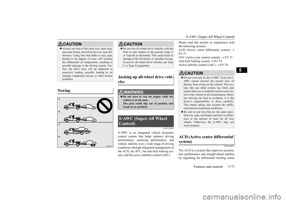
CAUTION Do not tow all-wheel dr
ive vehicles with the
front or rear wheels on the ground (Type A or Type B) as illustrated. This could result in damage to the drivetrain, or unstable towing. If you tow all-wheel drive vehicles, use TypeC or Type D equipment.
Jacking up all-wheel drive vehi- cles
WA R N I N G Do not start or run the engine while the vehicle is on the jack. The jack could slip out of position andresult in an accident.
S-AWC (Super-All Wheel Control)
CAUTION Do not over-rely on the S-AWC. Even the S- AWC cannot prevent the natural laws ofphysics from acting on the vehicle. This sys- tem, like any other system, has limits and cannot help you to maintain traction and con-trol of the vehicle in all circumstances. Reck- less driving can lead to accidents. It is the driver’s responsibility to drive carefully.This means taking into account the traffic, road and environmental conditions. Be sure to use tires that are the same speci- fied size, type, and brand, and have no differ- ence in the amount of wear for all fourwheels. Otherwise,
the S-AWC may not
work properly.
ACD (Active center differential system)
BK0200800US.bo
ok 71 ページ 2013年2月14日 木曜日 午後2時28分