stop start MITSUBISHI LANCER EVOLUTION 2014 10.G Owners Manual
[x] Cancel search | Manufacturer: MITSUBISHI, Model Year: 2014, Model line: LANCER EVOLUTION, Model: MITSUBISHI LANCER EVOLUTION 2014 10.GPages: 338, PDF Size: 40.99 MB
Page 35 of 338
Seat belts 4-10 Seat and restraint systems
4
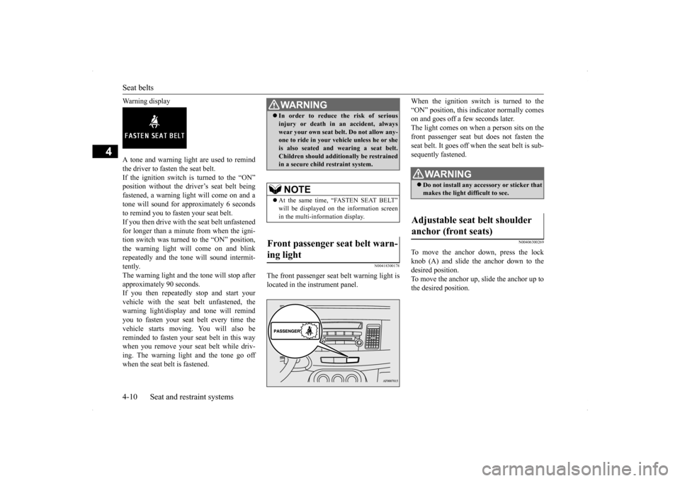
Warning display A tone and warning light are used to remind the driver to fasten the seat belt. If the ignition switch is turned to the “ON”position without the driver’s seat belt being fastened, a warning light will come on and a tone will sound for approximately 6 secondsto remind you to fasten your seat belt. If you then drive with the seat belt unfastened for longer than a minute from when the igni-tion switch was turned to the “ON” position, the warning light will come on and blink repeatedly and the tone will sound intermit-tently. The warning light and the tone will stop after approximately 90 seconds.If you then repeatedly stop and start your vehicle with the seat belt unfastened, the warning light/display and tone will remindyou to fasten your seat belt every time thevehicle starts moving. You will also be reminded to fasten your seat belt in this way when you remove your seat belt while driv-ing. The warning light and the tone go off when the seat belt is fastened.
N00418300178
The front passenger seat belt warning light is located in the instrument panel.
When the ignition switch is turned to the “ON” position, this indicator normally comes on and goes off a few seconds later. The light comes on when a person sits on thefront passenger seat but does not fasten the seat belt. It goes off when the seat belt is sub- sequently fastened.
N00406300269
To move the anchor down, press the lock knob (A) and slide the anchor down to the desired position.To move the anchor up, slide the anchor up to the desired position.
WA R N I N G In order to reduce the risk of serious injury or death in an accident, always wear your own seat belt. Do not allow any- one to ride in your vehicle unless he or she is also seated and wearing a seat belt.Children should additionally be restrained in a secure child restraint system.NOTE
At the same time, “FASTEN SEAT BELT” will be displayed on the information screen in the multi-information display.
Front passenger seat belt warn- ing light
WA R N I N G Do not install any accessory or sticker that makes the light difficult to see.
Adjustable seat belt shoulder anchor (front seats)
BK0200800US.bo
ok 10 ページ 2013年2月14日 木曜日 午後2時28分
Page 62 of 338
5
Features and controlsBreak-in period ................
.................................................................5-3
Keys .....................................................
.............................................5-3
Electronic immobilizer (Anti-theft starting system) .........................5-4 Keyless entry system (if so equipped) ..............................................5-7Free-hand Advanced Security Transmitter (F.A.S.T.-key) (if so equipped)................................
..................................................... 5-11
Door locks........................
...............................................................5-34
Power door locks .............
...............................................................5-36
“Child safety locks” for
rear door...................................................5-37
Trunk lid ....................................
.....................................................5-37
Inside emergency trunk lid
release .................................................5-39
Theft-alarm system ..........
...............................................................5-40
Power windows................
...............................................................5-42
Sunroof (if so equipped
) .........................................
........................5-44
Parking brake ...................
...............................................................5-47
Steering wheel tilt lock lever ..........................................................5-47Inside day/night rearview
mirror ....................................................5-48
Outside rearview mirr
ors ................................................................5-49
Ignition switch .................
...............................................................5-50
Steering wheel lock..........
...............................................................5-52
Starting and stopping the e
ngine ....................................................5-53
Turbocharger operation
...........................................
........................5-55
Clutch pedal operation (if so equipped)..........................................5-56Manual transaxle (if so equipped) ..................................................5-57 Twin Clutch SST (Sportronic Shif
t Transmission) (if so equipped)
...................................................................
..................................5-58
All-wheel drive system
...........................................
........................5-70
Cautions on handling of all-wheel drive vehicles ..........................5-70
S-AWC (Super-All Wheel
Control)................................................ 5-71
Anti-lock braking syst
em ......................................
......................... 5-74
Active stability control
(ASC) .....................
................................... 5-76
Limited-slip differenti
al.........................................
......................... 5-79
Service brake ..................
.................................................
............... 5-79
Brake assist system
................................................
......................... 5-80
Power steering system
...........................................
......................... 5-80
Cruise control .................
.................................................
............... 5-81
Tire pressure monitoring
system .................................................... 5-85
Instrument cluster .
.................................................
......................... 5-89
Multi-information disp
lay .....................................
......................... 5-91
Indicator light, warning light, and information screen display list
.................................................................
................................. 5-111
Indicators ..................................
.................................................... 5-121
Warning lights.................
.................................................
............. 5-122
Information screen disp
lay ...................................
....................... 5-123
Combination headlights and dimmer switch ............................... 5-125 Turn signal lever ...
.................................................
....................... 5-131
Hazard warning flasher
switch ..................................................... 5-131
Front fog light switch
............................................
....................... 5-131
Wiper and washer swit
ch ......................................
....................... 5-132
Electric rear window def
ogger switch .......................................... 5-136
Horn switch ..............................
.................................................... 5-137
Link System ..............................
.................................................... 5-137
Bluetooth
® 2.0 interface ...........
.................................................... 5-137
USB input terminal .........
.................................................
............. 5-158
Sun visors .................................
.................................................... 5-161
12 V power outlet ...........
.................................................
............. 5-162
BK0200800US.bo
ok 1 ページ 2013年2月14日 木曜日 午後2時28分
Page 78 of 338
Free-hand Advanced Security Transmit
ter (F.A.S.T.-key) (if so equipped)
Features and controls 5-17
5
N00513700077
Slowly turn the ignition switch to the “LOCK” position while pressing it. First, set the gearshift lever to the “P” (PARK) position, and then slowly turn theignition switch to the “LOCK” position while pressing it.
N00503500199
With the F.A.S.T.-key, warnings are given through buzzers and displays on the informa-tion screen in the multi-information display in order to prevent mistaken operations or vehicle theft.When a warning operates, be sure to check the vehicle and the F.A.S.T.-key. A warning is also displayed if there is a problem in theF. A . S . T. - k e y. If the following warning displays, contact an authorized Mitsubishi Motors dealer.
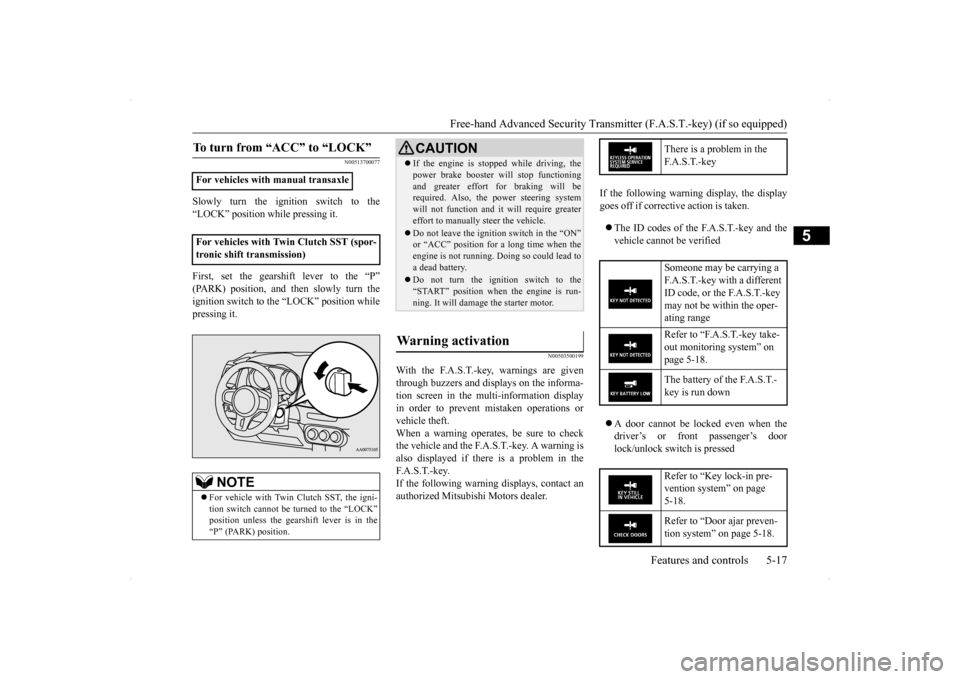
If the following warning display, the display goes off if corrective action is taken. The ID codes of the F.A.S.T.-key and the vehicle cannot be verified A door cannot be locked even when the driver’s or front passenger’s door lock/unlock switch is pressed
To turn from “ACC” to “LOCK”
For vehicles with manual transaxle For vehicles with Twin Clutch SST (spor- tronic shift transmission)
NOTE
For vehicle with Twin Clutch SST, the igni- tion switch cannot be turned to the “LOCK” position unless the gearshift lever is in the“P” (PARK) position.
CAUTION If the engine is stopped while driving, the power brake booster will stop functioning and greater effort for braking will be required. Also, the power steering system will not function and it will require greatereffort to manually steer the vehicle. Do not leave the ignition switch in the “ON” or “ACC” position for a long time when the engine is not running. Doing so could lead to a dead battery. Do not turn the ignition switch to the “START” position when the engine is run-ning. It will damage the starter motor.
Warning activation
There is a problem in the F. A . S . T. - k e y Someone may be carrying a F.A.S.T.-key with a different ID code, or the F.A.S.T.-key may not be within the oper- ating range Refer to “F.A.S.T.-key take- out monitoring system” on page 5-18. The battery of the F.A.S.T.- key is run down Refer to “Key lock-in pre- vention system” on page 5-18. Refer to “Door ajar preven- tion system” on page 5-18.
BK0200800US.bo
ok 17 ページ 2013年2月14日 木曜日 午後2時28分
Page 84 of 338

Free-hand Advanced Security Transmit
ter (F.A.S.T.-key) (if so equipped)
Features and controls 5-23
5
3. Insert the emergency key into the ignition switch, and slowly push and turn.
1. [For vehicles with manual transaxle] Push the emergency key in at the “ACC” position and keep it
depressed until it is
turned to the “LOCK” position, andremove. [For vehicles with Twin Clutch SST (sportronic shift transmission)]First, set the gearshift lever to the “P” (PARK) position, and then slowly turn the ignition switch to the “LOCK” positionwhile pressing it. 2. Install the cover of the ignition switch.
3. Reinsert the emergency key into the F. A . S . T. - k e y.
NOTE
When the ignition switch cannot be turned from the “LOCK” position to the “ACC” position, turn the ignition switch while turn-ing the steering wheel in both directions.
To turn from “ACC” to “LOCK”
NOTE
For vehicles with Twin Clutch SST, the emergency key cannot be removed unless thegearshift lever is set to the “P” (PARK) posi- tion.
NOTE
Always install the cover of the ignition switch when not using the emergency key.Not doing so could cause damage if foreign material such as dust
gets into the keyhole of
the ignition switch.CAUTION Do not turn the ignition switch to the LOCK position while the vehicle is moving. This will cause the steering wheel to lock, makingit impossible to operate the vehicle. If the engine is stopped while driving, the power brake booster will stop functioning and greater effort for braking will be required. Also, the power steering systemwill not function and it will require greater effort to manually steer the vehicle. Do not leave the ignition switch in the “ON” or “ACC” position for a long time when the engine is not running. The battery will rundown. Do not turn the ignition switch to the “START” position when the engine is run- ning. It will damage the starter motor.
BK0200800US.bo
ok 23 ページ 2013年2月14日 木曜日 午後2時28分
Page 101 of 338
Theft-alarm system 5-40 Features and controls
5
N00510201270
The theft-alarm system is designed to provide protection from unauthorized entry into thevehicle. This system is operated in three stages: the first is the “armed” stage, the sec- ond is the “alarm” stage, and third is the “dis-armed” stage. If triggered, the system provides both audible and visual alarm sig- nals. Park the vehicle and stop the engine. Arm the system as described below. 1. Turn the ignition switch to the “LOCK” position.Also, if a key was used to start the engine, remove the key from the ignition switch. 2. Make sure that the trunk lid and enginehood are closed.
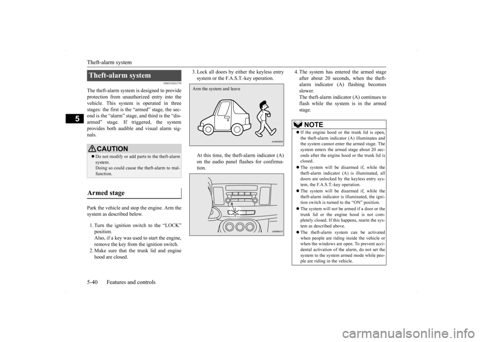
3. Lock all doors by either the keyless entry system or the F.A.S.T.-key operation. At this time, the theft-alarm indicator (A) on the audio panel flashes for confirma- tion.
4. The system has entered the armed stage after about 20 seconds, when the theft- alarm indicator (A) flashing becomes slower.The theft-alarm indicator (A) continues to flash while the system is in the armed stage.
Theft-alarm system
CAUTION Do not modify or add parts to the theft-alarm system.Doing so could cause the theft-alarm to mal- function.
Armed stage
Arm the system and leave
NOTE
If the engine hood or the trunk lid is open, the theft-alarm indicator (A) illuminates andthe system cannot enter the armed stage. The system enters the armed stage about 20 sec- onds after the engine hood or the trunk lid isclosed. The system will be disarmed if, while the theft-alarm indicator (A) is illuminated, all doors are unlocked by the keyless entry sys- tem, the F.A.S.T.-key operation. The system will be disarmed if, while the theft-alarm indicator is illuminated, the igni-tion switch is turned to the “ON” position. The system will not be
armed if a door or the
trunk lid or the engine hood is not com- pletely closed. If this happens, rearm the sys- tem as described above. The theft-alarm system can be activated when people are riding inside the vehicle or when the windows are open. To prevent acci- dental activation of the alarm, do not set thesystem to the system armed mode while peo- ple are riding in the vehicle.
BK0200800US.bo
ok 40 ページ 2013年2月14日 木曜日 午後2時28分
Page 113 of 338
![MITSUBISHI LANCER EVOLUTION 2014 10.G Owners Manual Steering wheel lock 5-52 Features and controls
5
N00512500010
[For vehicles equipped with the F.A.S.T.- key]For information on operations for vehiclesequipped with the F.A.S.T.-key, refer to “F.A.S. MITSUBISHI LANCER EVOLUTION 2014 10.G Owners Manual Steering wheel lock 5-52 Features and controls
5
N00512500010
[For vehicles equipped with the F.A.S.T.- key]For information on operations for vehiclesequipped with the F.A.S.T.-key, refer to “F.A.S.](/img/19/7475/w960_7475-112.png)
Steering wheel lock 5-52 Features and controls
5
N00512500010
[For vehicles equipped with the F.A.S.T.- key]For information on operations for vehiclesequipped with the F.A.S.T.-key, refer to “F.A.S.T.-key: Steering wheel lock” on page 5-19. [Except for vehicles equipped with the F. A . S . T. - k e y ]
Remove the key at the “LOCK” position. Turn the steering wheel until it is locked. Turn the key to the “ACC” position while moving the steering wheel slightly.
NOTE
For vehicles with a Twin Clutch SST, the key cannot be removed unless the gearshift lever is set to the “P” (PARK) position, whichallows the ignition switch to turn to the “LOCK” position.CAUTION Do not remove the ignition key from the ignition switch while driving. The steering wheel will lock, causing loss of control. If the engine is turned off while driving, the power brake booster will stop functioning and braking efficiency will be reduced. Also,the power steering system will not function and it will require greater effort to manually steer the vehicle. Do not leave the key in the “ON” position for a long time when the engine is not running.This will cause the battery to run down.Twin Clutch SST
Do not turn the key to the “START” position when the engine is running. It will damage the starter motor.
Steering wheel lock
CAUTION
To l o c k To u n l o c k
CAUTION Remove the key when leaving the vehicle.NOTE
If the front wheels are turned, the anti-theft lock may sometimes make it difficult to turn the key from “LOCK” position to “ACC” position. Firmly turn the steering wheel tothe left or to the right as you turn the key.
BK0200800US.bo
ok 52 ページ 2013年2月14日 木曜日 午後2時28分
Page 114 of 338
Starting and stopping the engine Features and controls 5-53
5
N00542100073
Do not operate the starter motor continu- ously for longer than
15 seconds as this
could run the battery down or damage thestarter motor. If the engine does not start,turn the ignition switch back to the “LOCK” position, wait a few seconds, and then try again. Trying repeatedly withthe engine or starter motor still turning will damage the starter mechanism. If the engine will not start because the bat- tery is weak or discharged, refer to “Jump-starting the engine” (on page 8-2) for instructions. The engine is warmed up enough for driv- ing when the bar graph of engine coolant temperature display starts to move. Driv-ing before the bar graph moves may cause deterioration of turbocharger performance and driveability. A longer warm up periodwill only consume extra fuel. On vehicles equipped with the Twin Clutch SST, the following may occur afterthe engine is started, but they do not indi- cate an abnormality.
• You may hear operational sounds of the Twin Clutch SST and you may feel vibration in the vehicle body. • If you shift the gearshift lever into the“N” (NEUTRAL) position and depress the accelerator pedal, increases in the engine speed will be limited.
N00542200133
[For vehicles equipped with the F.A.S.T.-key]
For information on operation for vehicles equipped with the F.A.S.T.-key, refer to “F.A.S.T.-key: Starting the engine” on page 5-19. [Except for vehicles equipped with the F. A . S . T. - k e y ] Your vehicle is equipped with an electroni- cally controlled fuel injection system, whichautomatically controls the release of fuel. There is usually no need to depress the accel- erator pedal when starting the engine.The starter should not be run for more than 15seconds at a time. To prevent battery drain, wait a few seconds between attempts to restart the engine. 1. Make sure all occupants are properly seated with seat belts fastened. 2. Insert the ignition key. 3. Make sure the parking brake is applied.4. Press and hold the brake pedal down with your right foot. 5. Press and hold the clutch pedal all the waydown (manual transaxle).
Starting and stopping the engine Tips for starting
WA R N I N G Never run the engine in a closed or poorly ventilated area any longer than is neededto move your vehicle out of the area. Car- bon monoxide gas, which is odorless and extremely poisonous, could build up andcause serious injury or death.CAUTION Do not push-start the vehicle.Do not run the engine
at high rpms or drive
at high speeds until the engine has had a chance to warm up. Release the ignition switch as soon as the engine starts. Otherwise, the starter motorwill be damaged.
Starting the engine
NOTE
For models equipped with a manual trans- axle, the starter will not operate unless the clutch pedal is fully depressed (Clutch inter-lock). This is a safety feature.
BK0200800US.bo
ok 53 ページ 2013年2月14日 木曜日 午後2時28分
Page 115 of 338

Starting and stopping the engine 5-54 Features and controls
5
6. On vehicles with manual transaxle, place the gearshift lever in the “N” (Neutral) position. On vehicles with Twin Clutch SST, makesure the gearshift lever is in the “P” (PARK) position. 7. Turn the ignition switch to the “ON” posi- tion and make certain that all warninglights are functioning properly before starting the engine. 8. Turn the ignition switch to the “START”position without pressing the accelerator pedal. Release the key when the engine starts.
After several attempts, you may experience that the engine still does not start.
1. Make sure that all electric devices, such as lights, air conditioning blower and rear window defogger, are turned off. 2. While depressing the brake pedal on vehi-cles equipped with Twin Clutch SST or the clutch pedal on the vehicles equipped with manual transaxle, press the accelera-tor pedal halfway and hold it there, then crank the engine. Release the accelerator pedal, immediately after the engine starts.3. If the engine still will not start, the enginecould be flooded with too much gasoline. While depressing the brake pedal on vehi- cles equipped with Twin Clutch SST orthe clutch pedal on the vehicles equipped with manual transaxle, push the accelera- tor pedal all the way down and hold itthere, then crank the engine for 5 to 6 sec- onds. Return the ignition switch to the “LOCK” position and release the acceler-ator pedal. Wait a few seconds, and then crank the engine again for 5 to 6 seconds while depressing the brake pedal or theclutch pedal, but do not push the accelera- tor pedal. Release the ignition key if the engine starts. If the engine fails to start,repeat these procedures. If the engine still will not start, contact your local Mitsubi- shi Motors dealer or a repair facility ofyour choice for assistance.
When the ambient temperature is -22 °F (-30 °C) or lower, it may not be possible to start from a standstill even with the gearshift lever in the “D” (DRIVE) position.This phenomenon occurs because the trans- mission has not warmed up sufficiently; it does not indicate a problem. If it occurs,place the gearshift lever in the “P” (PARK)position and let the engine idle for at least 10 minutes. The transmission will warm up, and you willbe able to start normally. Do not leave the vehicle during warm-up operation.
N00547600031
At high altitude locations, the idle speed maybe higher. This is done in order to stabilizethe idle speed when the power steering sys- tem and other systems operate. It does not indicate a malfunction.
N00542300075
1. Bring the vehicle to a complete stop.
NOTE
On vehicles with Twin Clutch SST, the starter will not operate unless the gearshift lever is in the “P” (PARK) position or thegearshift lever is in the “N” (NEUTRAL) position with the brake pedal depressed. For safety reasons, start the engine in the “P”(PARK) position so that the wheels are locked.
When the engine is hard to start
Startability of Twin Clutch SST vehicle with ambient temperature of -22 °F (-30 °C) or lower Idle speed in high altitude area Stopping the engine
BK0200800US.bo
ok 54 ページ 2013年2月14日 木曜日 午後2時28分
Page 116 of 338
Turbocharger operation
Features and controls 5-55
5
2. Fully engage the parking brake while depressing the brake pedal. 3. For vehicles with a manual transaxle, turn the ignition switch to the “LOCK” posi-tion to stop the engine, and then move the gearshift lever to the 1st (on a uphill) or “R” (Reverse) (on a downhill) position.For vehicles with Twin Clutch SST, place the gearshift lever in the “P” (PARK) position, and then turn the ignition switchto the “LOCK” position to stop theengine.
N00537300077
NOTE
For vehicles with Twin Clutch SST, the engine will stop and the vehicle power will turn off approximately 1 second after the ignition switch is turned to the “LOCK” position. The reason for this is that, in the time from when the ignition switch is turned to the“LOCK” position until the engine stops, the gears inside the Twin Clutch SST disengage so that the engine will start smoothly thenext time it is started. Two clutches installed in the Twin Clutch SST alternately engage and disengage toachieve smooth shifting. In addition, the gear on the side with the free clutch is engaged, therefore, quick shifting isperformed. If the engine was stopped with the gear engaged like this, it would provide resistancethe next time the engine is started. Therefore, the gear disengages in the approximately 1- second period until the engine stops. For vehicles with Twin Clutch SST, do not operate the gearshift lever or the acceleratorpedal for approximately 1 second until the engine stops.
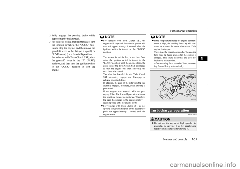
If the temperature inside the engine compart- ment is high, the cooling fans (A) will con- tinue to operate for some time even if the engine is stopped. Therefore, the operation sound of the coolingfans may be heard even after the engine is stopped. This sound is normal and does not indicate a malfunction.After operating for a period of time, the cool- ing fans will stop automatically.
Turbocharger operation
CAUTION Do not run the engine at high speeds (for example, by revving it or by accelerating rapidly) immediately after starting it.NOTE
BK0200800US.bo
ok 55 ページ 2013年2月14日 木曜日 午後2時28分
Page 117 of 338
Clutch pedal operation (if so equipped) 5-56 Features and controls
5
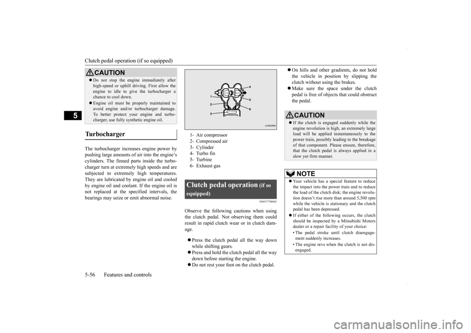
The turbocharger increases engine power by pushing large amounts of air into the engine’s cylinders. The finned parts inside the turbo-charger turn at extremely high speeds and are subjected to extremely high temperatures. They are lubricated by engine oil and cooledby engine oil and coolan
t. If the engine oil is
not replaced at the specified intervals, the bearings may seize or emit abnormal noise.
N00537700042
Observe the following cautions when usingthe clutch pedal. Not observing them couldresult in rapid clutch wear or in clutch dam- age. Press the clutch pedal all the way down while shifting gears. Press and hold the clutch pedal all the way down before starting the engine. Do not rest your foot on the clutch pedal.
On hills and other gradients, do not hold the vehicle in position by slipping the clutch without using the brakes. Make sure the space under the clutch pedal is free of objects that could obstruct the pedal.
Do not stop the engine immediately after high-speed or uphill driv
ing. First allow the
engine to idle to give the turbocharger a chance to cool down. Engine oil must be properly maintained to avoid engine and/or turbocharger damage. To better protect your engine and turbo-charger, use fully synthetic engine oil.
Turbocharger
CAUTION
1- Air compressor 2- Compressed air3- Cylinder 4- Turbo fin 5- Turbine6- Exhaust gasClutch pedal operation
(if so
equipped)
CAUTION If the clutch is engaged suddenly while the engine revolution is high, an extremely large load will be applied instantaneously to the power train, possibly leading to the breakageof that component. Please ensure, therefore, that the clutch pedal is always applied in a slow yet firm manner.NOTE
Your vehicle has a special feature to reduce the impact into the power train and to reduce the load of the clutch disk; the engine revolu-tion doesn’t rise more than around 5,500 rpm while the vehicle is stationary and the clutch pedal has been depressed. If either of the following occurs, the clutch should be inspected by a Mitsubishi Motors dealer or a repair facility of your choice: • The pedal stroke until clutch disengage- ment suddenly increases. • The engine revs when the clutch is not dis- engaged.
BK0200800US.bo
ok 56 ページ 2013年2月14日 木曜日 午後2時28分