ignition MITSUBISHI LANCER EVOLUTION 2015 10.G Owners Manual
[x] Cancel search | Manufacturer: MITSUBISHI, Model Year: 2015, Model line: LANCER EVOLUTION, Model: MITSUBISHI LANCER EVOLUTION 2015 10.GPages: 338, PDF Size: 43.12 MB
Page 248 of 338
Automatic air conditioning with
Celsius scale (if so equipped)
Comfort controls 7-9
7
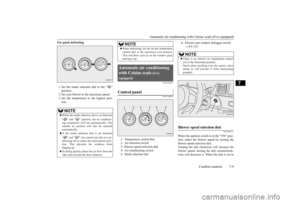
For quick defrosting 1. Set the mode selection dial to the “ ” position. 2. Set your blower to the maximum speed. 3. Set the temperature to the highest posi-tion.
N00731500255 N00711800483
N00736900111
When the ignition switch is in the “ON” posi- tion, select the blower speed by turning the blower speed selection dial.Turning the dial clockwise will increase the blower speed; turning the dial counterclock- wise will decrease it. When the dial is set to
NOTE
While the mode selection dial is set between “ ” and “ ” position, the air condition- ing compressor will run automatically. The outside air position will also be selectedautomatically. If the mode selection dial is set between “ ” and “ ” you cannot turn the air con- ditioning off or select the recirculation posi-tion. This prevents the windows from fogging up. To defog quickly, direct
the air flow from the
side vents toward the door windows.
When defrosting, do not set the temperature control dial to the maximum cool position. This will blow cool air on the window glass and fog it up.
Automatic air conditioning with Celsius scale
(if so
equipped)Control panel
1- Temperature control dial 2- Air selection switch 3- Blower speed selection dial 4- Air conditioning switch5- Mode selection dial
NOTE
6- Electric rear window defogger switch
P.5-135NOTE
There is an interior air temperature sensor (A) in the illustrated position.Never place anything over the sensor, since doing so will prevent it from functioning properly.
Blower speed selection dial
BK0210800US.bo
ok 9 ページ 2014年4月8日 火曜日 午前11時28分
Page 259 of 338
If the vehicle breaks down 8-2 For emergencies
8
N00836300190
If your vehicle breaks down on the road, move to the shoulder and turn on the hazardwarning flashers. If there is no shoulder, or the shoulder is not safe, drive in the right lane slowly, with the hazard lights flashing, untilyou come to a safe stopping place. Keep the flashers flashing. If the engine stops, there will be no power assist to the steering and brakes, making these difficult to use. The brake booster will not work, so the brakes will not grip well. The brake pedalwill be harder to press than usual. Since there is no power steering assist, the steering wheel will be hard to turn.
Get help from your passengers, bystanders, etc. to push the vehicl
e and move it to a safe
zone.
N00836400670
If the engine cannot be started because the battery is weak or dead, you can start it withthe battery from another vehicle using jumper cables.
1. Take off any metal jewelry such as watch bands or bracelets that might make an accidental electrical contact. 2. Position the vehicles close enoughtogether so that the jumper cables can reach, but be sure the vehicles aren’t touching each other. 3. You could be injured if the vehicles move. Set the parking brake firmly on each vehi- cle. Put an automatic transaxle, Twin Clutch SST or CVT in “P” (PARK) or amanual transaxle in “N” (Neutral). Turn the ignition switch to the “LOCK” posi- tion.
If the vehicle breaks down If the engine stops/fails When the engine fails at the intersection
Jump-starting the engine
WA R N I N G Follow the procedure described in this sec- tion when using the jump cable to start the engine. Failure to follow these instructions can cause serious injury or death.CAUTION Do not try to start your vehicle by pushing or towing. Vehicles with Twin Clutch SST can- not be started this way. Pushing or towing avehicle that has a manual transaxle may overheat and damage the catalytic converter. Also, there is more ri
sk of an accident when
a vehicle is being pushed or towed.NOTE
Although the battery in your vehicle is located in the trunk (refer to page 9-11), use the joint terminal in the engine compartment to jump start the engine.
CAUTION Check the other vehicle. It must have a 12- volt battery. If the other system isn’t 12-volt, both systems can be damaged.WA R N I N G Turn the ignition switch to the “LOCK” position on both vehicles. Make sure that the cables or your clothes cannot be caught by the fan or drive belt. Personalinjury could result. NOTE
Turn off all lights, heater, and other electrical loads. This will avoid sparks and help saveboth batteries.
BK0210800US.bo
ok 2 ページ 2014年4月8日 火曜日 午前11時28分
Page 263 of 338
How to change a tire 8-6 For emergencies
8
N00836900763
Before changing a tire, first stop your vehicle in a safe, flat location. 1. Park the vehicle on level and stable ground. 2. Set the parking brake firmly.3. On vehicles with manual transaxle, turn the ignition switch to the “LOCK” posi- tion, and move the gearshift lever to the“R” (Reverse) position. On vehicles with Twin Clutch SST, move the gearshift lever to the “P” (PARK)position, and turn the ignition switch to the “LOCK” position. 4. Turn on the hazard flashers and set up awarning triangle, flashing signal light, etc., at an adequate distance from the vehicle, and have all your passengersleave the vehicle.
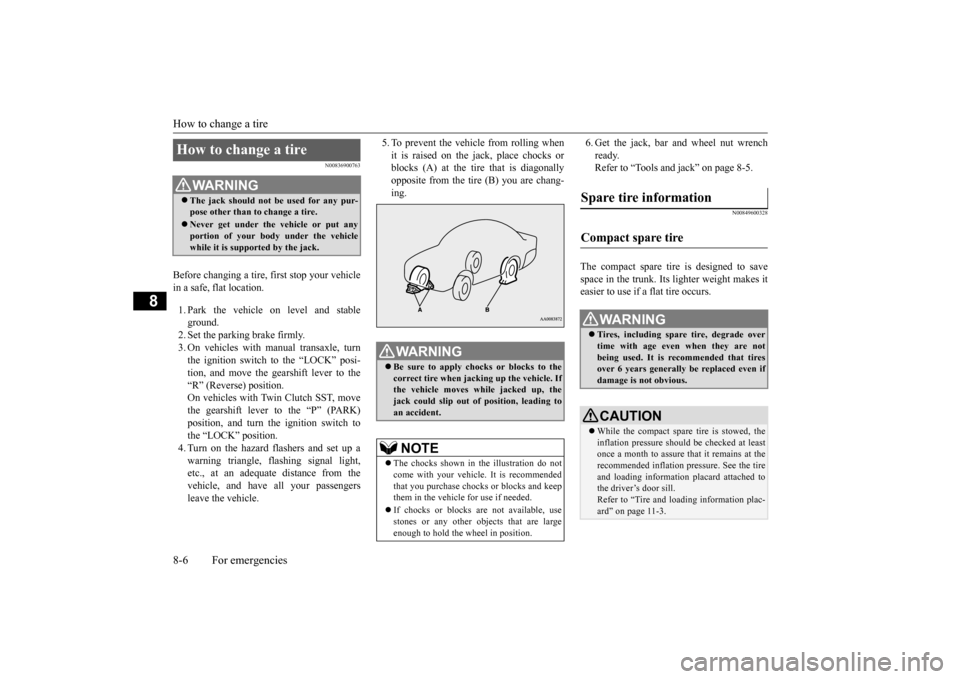
5. To prevent the vehicle from rolling when it is raised on the jack, place chocks or blocks (A) at the tire that is diagonally opposite from the tire (B) you are chang-ing.
6. Get the jack, bar and wheel nut wrench ready. Refer to “Tools and jack” on page 8-5.
N00849600328
The compact spare tire is designed to save space in the trunk. Its lighter weight makes it easier to use if a flat tire occurs.
How to change a tire
WA R N I N G The jack should not be used for any pur- pose other than to change a tire. Never get under the vehicle or put any portion of your body under the vehicle while it is supported by the jack.
WA R N I N G Be sure to apply chocks or blocks to the correct tire when jacking up the vehicle. Ifthe vehicle moves while jacked up, the jack could slip out of position, leading to an accident.NOTE
The chocks shown in the illustration do not come with your vehicle. It is recommended that you purchase chocks or blocks and keepthem in the vehicle for use if needed. If chocks or blocks are not available, use stones or any other objects that are large enough to hold the wheel in position.
Spare tire information Compact spare tire
WA R N I N G Tires, including spare tire, degrade over time with age even when they are notbeing used. It is recommended that tires over 6 years generally be replaced even if damage is not obvious.CAUTION While the compact spare tire is stowed, the inflation pressure should be checked at least once a month to assure that it remains at the recommended inflation pressure. See the tire and loading information placard attached tothe driver’s door sill. Refer to “Tire and loading information plac- ard” on page 11-3.
BK0210800US.bo
ok 6 ページ 2014年4月8日 火曜日 午前11時28分
Page 280 of 338
Manual transaxle oil (if so equipped) Vehicle care and maintenance 9-9
9
N00938200165
Whenever the manual transaxle oil level is checked, add oil to maintain the proper level, if necessary. Refill or change the oil according to the table.
N00938300049
The Twin Clutch Sportronic shift transmis-sion (Twin Clutch SST) should be maintained and serviced by an authorized Mitsubishi Motors dealer or a repair facility of yourchoice to obtain the best performance and longest life. It is impor
tant that the transmis-
sion fluid is kept at the correct level.
Use only Mitsubishi Motors Genuine SSTF-I to ensure optimum transmission performance. Mitsubishi Motors Corporation does not rec- ommend the addition of any fluid additives to the transmission.
N00938400255
Whenever the transfer oil level is checked,add oil as necessary to maintain the proper level. Fill or change the oil according to thetable.
N00915200243
Whenever the oil level is checked, add oil asnecessary to maintain the proper level.Fill or change oil according to the table.
N00915300013
Remove the lid on the trunk room right side trim. Check the fluid level in the reservoir 90 min-utes or more after turning the ignition switch to the “LOCK” position. Check to make certain that the AWC controlfluid level is always between the “MAX” and “MIN” level markings on the fluid reservoir and refill the fluid, if necessary.
Manual transaxle oil
(if so
equipped)Oil type
Lubricant
Mitsubishi Motors Genuine NEW MULTI GEAR OIL API
Classification GL-3
Viscosity range
SAE 75W-80
Twin Clutch Sportronic shift transmission (Twin Clutch SST) fluid
(if so equipped)
Fluid type
CAUTION Using the improper transmission fluid may damage the transaxle.
Special additives
Transfer oil Oil type Lubri- cant
Mitsubishi Motors Genuine LSD
gear oil or equivalent
Rear axle oil Oil type Lubri- cant
For differen- tial mecha- nism
Mitsubishi Motors Genuine LSD gear
oil
For torque transfer mechanism
MITSUBISHI MOTORS Genu- ine ATF SP III
AWC control fluid To check the fluid level
BK0210800US.bo
ok 9 ページ 2014年4月8日 火曜日 午前11時28分
Page 292 of 338
General maintenance
Vehicle care and maintenance 9-21
9
N00940900244
Spark plugs must fire properly for good engine performance and emission-control.Do not reuse them by cleaning or regapping. Change them at the mileage listed in the “WARRANTY AND MAINTENANCEMANUAL”.
N00941000053
Check the hose surfaces for any heat andmechanical damage, hard and brittle rubber,cracking, tears, cuts and abrasions. Pay spe- cial attention to the hoses closest to high heat sources such as the exhaust manifold. Checkall the hose connections, such as clamps and couplings, to make sure
they are secure and
that there are no leaks. If you see any wear ordamage, replace the hoses immediately.
N00950100050
Have the valve clearance checked at anauthorized Mitsubishi Motors dealer at themileage specified in the “WARRANTY AND MAINTENANCE MANUAL”. If the engine sounds abnormally loud, haveadjustments made by an authorized Mitsubishi Motors dealer.
N00941300085
Check these regularly for damage or leaks in the fuel lines and connections. Check the fuel tank filler cap for damage or looseness. Pay special attention to the fuel lines closest to
high heat sources such as the exhaust mani- fold.
N00941400116
If the fuel-vapor vent line is clogged or dam- aged, the fuel-vapor mixture will escape, pol- luting the air.Have the system checked at an authorized Mitsubishi Motors dealer at the mileage spec- ified in the “WARRANTY AND MAINTE-NANCE MANUAL”.
N00941500159
The next pages list the maintenance servicerecommended by Mitsubishi Motors Corpo- ration. In addition to the general maintenance that needs to be performed at the times listed,
NOTE
To meet government regulations and pro- mote cleaner air, your vehicle is equipped with an onboard diagnostic system (OBD). The engine electronic control module that controls OBD functions stores various data(especially about the exhaust emissions). This data will be erased if the battery cable is disconnected, which could make a rapiddiagnosis difficult. Do not disconnect the battery cable when the engine malfunction indicator (“SERVICE ENGINE SOON” or“Check engine light”) is on.
Spark plugs
NOTE
Use the spark plugs listed under “Engine specifications” on page 11-4 or plugs that are exactly the same. Other plugs could causeengine damage, performance problems or radio noise.
Fuel hoses Intake valve clearance Fuel system (tank, pipe line and connection, and fuel tank filler cap)
WA R N I N G If you see a fuel leak or if you smell fuel, do not run the engine. Any spark (includ- ing from the ignition), flame or smokingmaterial could cause an explosion or fire. Call an authorized Mitsubishi Motors dealer or a repair facility of your choicefor assistance.
Evaporative emission control system (except evaporative emission canister) General maintenance
BK0210800US.bo
ok 21 ページ 2014年4月8日 火曜日 午前11時28分
Page 296 of 338
Fuses
Vehicle care and maintenance 9-25
9
* - Fusible link Some fuses may not be installed on your vehicle, depending on the vehicle modelor specifications. The table above shows the main equip- ment corresponding to each fuse.
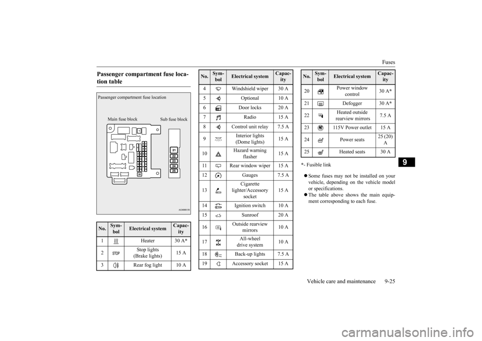
Passenger compartment fuse loca- tion table No.
Sym- bol
Electrical system
Capac-ity
1 Heater 30 A
*
2
Stop lights (Brake lights)
15 A
3 Rear fog light 10 APassenger compartment fuse location
Main fuse block
Sub fuse block
4 Windshield wiper 30 A 5 Optional 10 A 6 Door locks 20 A 7Radio15 A8 Control unit relay 7.5 A 9
Interior lights (Dome lights)
15 A
10
Hazard warning
flasher
15 A
11 Rear window wiper 15 A 12 Gauges 7.5 A 13
Cigarette
lighter/Accessory
socket
15 A
14 Ignition switch 10 A 15 Sunroof 20 A 16
Outside rearview
mirrors
10 A
17
All-wheel drive system
10 A
18 Back-up lights 7.5 A 19 Accessory socket 15 ANo.
Sym- bol
Electrical system
Capac-ity
20
Power window
control
30 A
*
21 Defogger 30 A
*
22
Heated outside rearview mirrors
7.5 A
23 115V Power outlet 15 A24 Power seats
25 (20) A
25 Heated seats 30 ANo.
Sym- bol
Electrical system
Capac-ity
BK0210800US.bo
ok 25 ページ 2014年4月8日 火曜日 午前11時28分
Page 297 of 338
Fuses 9-26 Vehicle care and maintenance
9
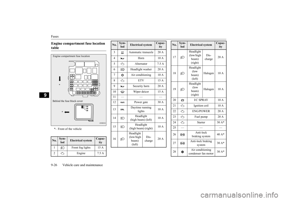
Engine compartment fuse location table * - Front of the vehicle
No.
Sym- bol
Electrical system
Capac-ity
1 Front fog lights 15 A 2 Engine 7.5 AEngine compartment fuse location
*
Behind the fuse block cover
*
3 Automatic transaxle 20 A 4 Horn 10 A 5 Alternator 7.5 A 6 Headlight washer 20 A 7 Air conditioning 10 A8 ETV 15 A 9 Security horn 20 A 10 Wiper deicer 15 A 11 — — — 12 Power gate 30 A 13
Daytime running
lights
10 A
14
Headlight
(high beam) (left)
10 A
15
Headlight
(high beam) (right)
10 A
16
Headlight (low/high beam) (left)
Dis- charge
20 A
No.
Sym- bol
Electrical system
Capac-ity
17
Headlight (low/high beam) (right)
Dis- charge
20 A
18
Headlight (low beam) (left)
Halogen 10 A
19
Headlight (low beam) (right)
Halogen 10 A
20 I/C SPRAY 10 A 21 Ignition coil 10 A 22 ENG/POWER 20 A 23 Fuel pump 20 A24 Starter 30 A
*
25 — — — 26
Anti-lock
braking system
40 A
*
27
Anti-lock braking
system
30 A
*
28
Air conditioning condenser fan motor
30 A
*
No.
Sym- bol
Electrical system
Capac-ity
BK0210800US.bo
ok 26 ページ 2014年4月8日 火曜日 午前11時28分
Page 298 of 338
Fuses
Vehicle care and maintenance 9-27
9
* - Fusible link Some fuses may not be installed on your vehicle, depending on the vehicle model or specifications. The table above shows the main equip- ment corresponding to each fuse.
There are no 7.5 A, 25 A or 30 A spare fuses. If a fuse of one of
these capacities blows,
replace it temporarily by borrowing one of the fuses indicated below.7.5 A: 10 A spare fuse 25 A: 20 A spare fuse 30 A: 30 A audio amplifier fuseReplace the borrowed fuse with a fuse that has the correct capacity as soon as possible.
N00901100052 N00954900027
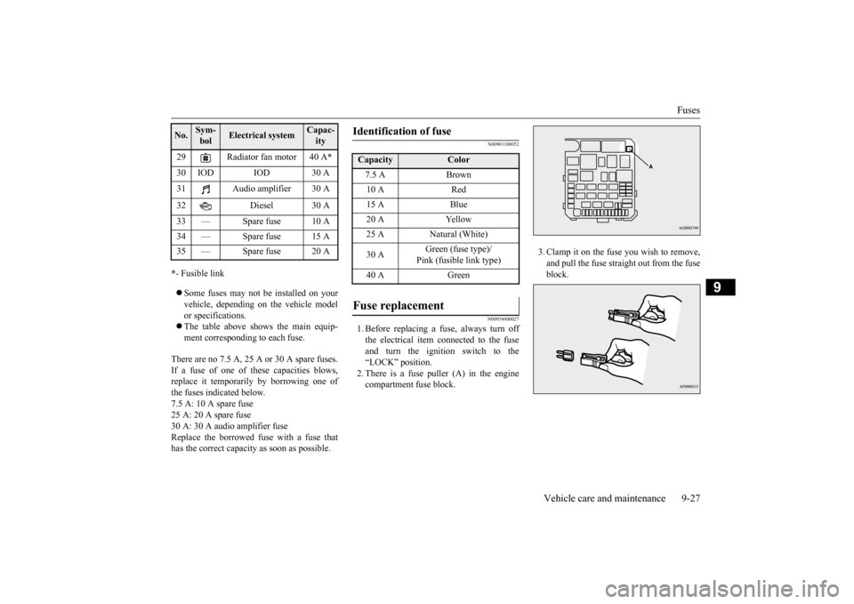
1. Before replacing a fuse, always turn off the electrical item connected to the fuse and turn the ignition switch to the“LOCK” position. 2. There is a fuse puller (A) in the engine compartment fuse block.
3. Clamp it on the fuse you wish to remove, and pull the fuse straight out from the fuse block.
29 Radiator fan motor 40 A
*
30 IOD IOD 30 A 31 Audio amplifier 30 A 32 Diesel 30 A 33 — Spare fuse 10 A 34 — Spare fuse 15 A35 — Spare fuse 20 ANo.
Sym- bol
Electrical system
Capac-ity
Identification of fuse Capacity
Color
7.5 A Brown10 A Red15 A Blue20 A Yellow25 A Natural (White) 30 A
Green (fuse type)/ Pink (fusible link type)
40 A Green
Fuse replacement
BK0210800US.bo
ok 27 ページ 2014年4月8日 火曜日 午前11時28分
Page 332 of 338
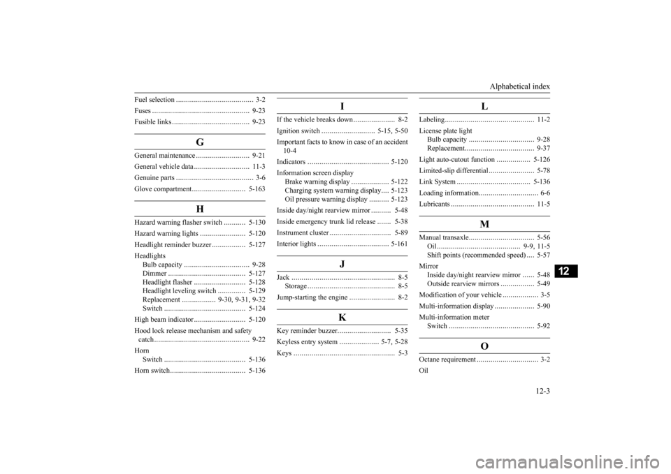
Alphabetical index
12-3
12
Fuel selection
....................
...................
3-2
Fuses
.........................
........................
9-23
Fusible links
..................
.....................
9-23
G
General maintenance
...........................
9-21
General vehicle data
............................
11-3
Genuine parts
....................
...................
3-6
Glove compartment
...........................
5-163
H
Hazard warning flasher switch
...........
5-130
Hazard warning lights
.......................
5-120
Headlight reminder buzzer
.................
5-127
Headlights
Bulb capacity
................
.................
9-28
Dimmer
....................
...................
5-127
Headlight flasher
..........................
5-128
Headlight leveling switch
..............
5-129
Replacement
.................
9-30
, 9-31
, 9-32
Switch
......................
...................
5-124
High beam indicator
..........................
5-120
Hood lock release mechanism and safety catch
........................
........................
9-22
Horn
Switch
......................
...................
5-136
Horn switch
...................
...................
5-136
I
If the vehicle breaks down
.....................
8-2
Ignition switch
...........................
5-15
, 5-50
Important facts to know in case of an accident 10-4 Indicators
....................
.....................
5-120
Information screen display
Brake warning display
...................
5-122
Charging system warning display
....
5-123
Oil pressure warning display
..........
5-123
Inside day/night rearview mirror
..........
5-48
Inside emergency trunk lid release
.......
5-38
Instrument cluster
................
...............
5-89
Interior lights
...................
.................
5-161
J
Jack
............................
........................
8-5
Storage
........................
....................
8-5
Jump-starting the engine
.......................
8-2
K
Key reminder buzzer
...........................
5-35
Keyless entry system
....................
5-7
, 5-28
Keys
...........................
........................
5-3
L
Labeling
........................
.....................
11-2
License plate light
Bulb capacity
................
.................
9-28
Replacement
..................
.................
9-37
Light auto-cutout function
.................
5-126
Limited-slip differential
.......................
5-78
Link System
..................
...................
5-136
Loading information
..............................
6-6
Lubricants
.....................
.....................
11-5
M
Manual transaxle
................
.................
5-56
Oil
.....................
.....................
9-9
, 11-5
Shift points (recommended speed)
....
5-57
Mirror
Inside day/night rearview mirror
......
5-48
Outside rearview mirrors
.................
5-49
Modification of your vehicle
..................
3-5
Multi-information display
....................
5-90
Multi-information meter
Switch
......................
.....................
5-92
O
Octane requirement
...............
................
3-2
Oil
BK0210800US.bo
ok 3 ページ 2014年4月8日 火曜日 午前11時28分