battery MITSUBISHI LANCER EVOLUTION IX 2005 User Guide
[x] Cancel search | Manufacturer: MITSUBISHI, Model Year: 2005, Model line: LANCER EVOLUTION IX, Model: MITSUBISHI LANCER EVOLUTION IX 2005Pages: 364, PDF Size: 14.38 MB
Page 70 of 364
MPI – ON-VEHICLE SERVICING13A-30
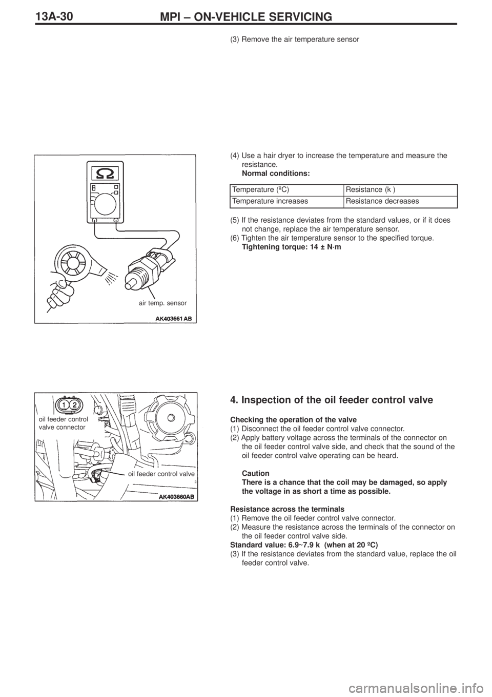
(3) Remove the air temperature sensor
(4) Use a hair dryer to increase the temperature and measure the
resistance.
Normal conditions:
air temp. sensor
Temperature (ºC)Resistance (kΩ)
Temperature increasesResistance decreases
(5) If the resistance deviates from the standard values, or if it does
not change, replace the air temperature sensor.
(6) Tighten the air temperature sensor to the specified torque.
Tightening torque: 14 ± N·m
4. Inspection of the oil feeder control valve
Checking the operation of the valve
(1) Disconnect the oil feeder control valve connector.
(2) Apply battery voltage across the terminals of the connector on
the oil feeder control valve side, and check that the sound of the
oil feeder control valve operating can be heard.
Caution
There is a chance that the coil may be damaged, so apply
the voltage in as short a time as possible.
Resistance across the terminals
(1) Remove the oil feeder control valve connector.
(2) Measure the resistance across the terminals of the connector on
the oil feeder control valve side.
Standard value: 6.9~7.9 kΩ (when at 20 ºC)
(3) If the resistance deviates from the standard value, replace the oil
feeder control valve.oil feeder control
valve connector
oil feeder control valve
Page 142 of 364
GENERAL INFORMATION - HOW TO READ THE WIRING DIAGRAMS0-4
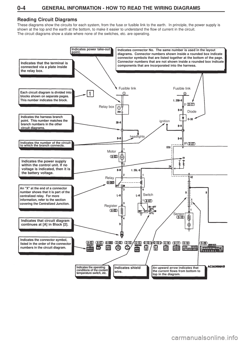
Reading Circuit Diagrams
These diagrams show the circuits for each system, from the fuse or fusible link to the earth. In principle, the power supply is
shown at the top and the earth at the bottom, to make it easier to understand the flow of current in the circuit.
The circuit diagrams show a state where none of the switches, etc. are operating.
Indicates power take-out
point.Indicates connector No. The same number is used in the layout
diagrams. Connector numbers shown inside a rounded box indicate
connector symbols that are listed together at the bottom of the page.
Connector numbers that are not shown inside a rounded box indicate
components that are incorporated into the harness.
Indicates that the terminal is
connected via a plate inside
the relay box.
Each circuit diagram is divided into
blocks shown on separate pages.
This number indicates the block.
Indicates the harness branch
point. This number matches the
branch numbers in the other
circuit diagrams.
Indicates the number of the circuit
to which the branch connects.
Indicates the power supply
within the control unit. If no
voltage is indicated, then it is
the battery voltage.
An "X" at the end of a connector
number shows that it is part of the
centralized relay. For more
information, refer to the section
covering the Centralized Junction.
Indicates that circuit diagram
continues at [A] in Block [2].
Indicates the connector symbol,
listed in the order of the connector
numbers in the circuit diagram.
Indicates the operating
conditions of the coolant
temperature switch, etc.Indicates shield
wire.An upward arrow indicates that
the current flows from bottom to
top in the diagram.
RegisterRelayMotor Relay boxFusible link
Fusible link
Diode
Sensor Switch
headlightsignition
Page 153 of 364

LAYOUT DIAGRAMS - GENERAL LAYOUT DIAGRAM1-3
Front
harness (RH)Control panelInstrument
panel harnessRoof harness
Floor harness (RH)
Battery
harness
Front harness (LH)
Front door
harness *Floor
harness (LH)Fuel harnessRear door harness *
Note :
1. This diagram shows the main wiring harnesses only.
2. The * symbol indicates that the harness is also fitted on the right-hand side.
General Layout Diagram
Page 156 of 364
LAYOUT DIAGRAMS - ENGINE / TRANSMISSION1-6
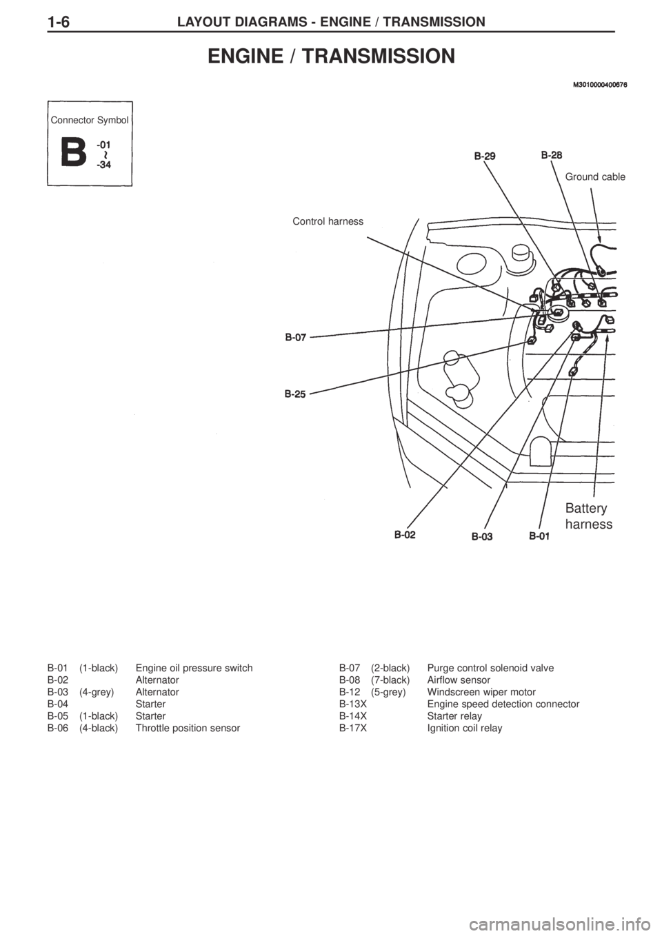
B-01 (1-black) Engine oil pressure switch
B-02 Alternator
B-03 (4-grey) Alternator
B-04 Starter
B-05 (1-black) Starter
B-06 (4-black) Throttle position sensorB-07 (2-black) Purge control solenoid valve
B-08 (7-black) Airflow sensor
B-12 (5-grey) Windscreen wiper motor
B-13X Engine speed detection connector
B-14X Starter relay
B-17X Ignition coil relay
ENGINE / TRANSMISSION
Connector Symbol
Control harnessGround cable
Battery
harness
Page 157 of 364
1-7
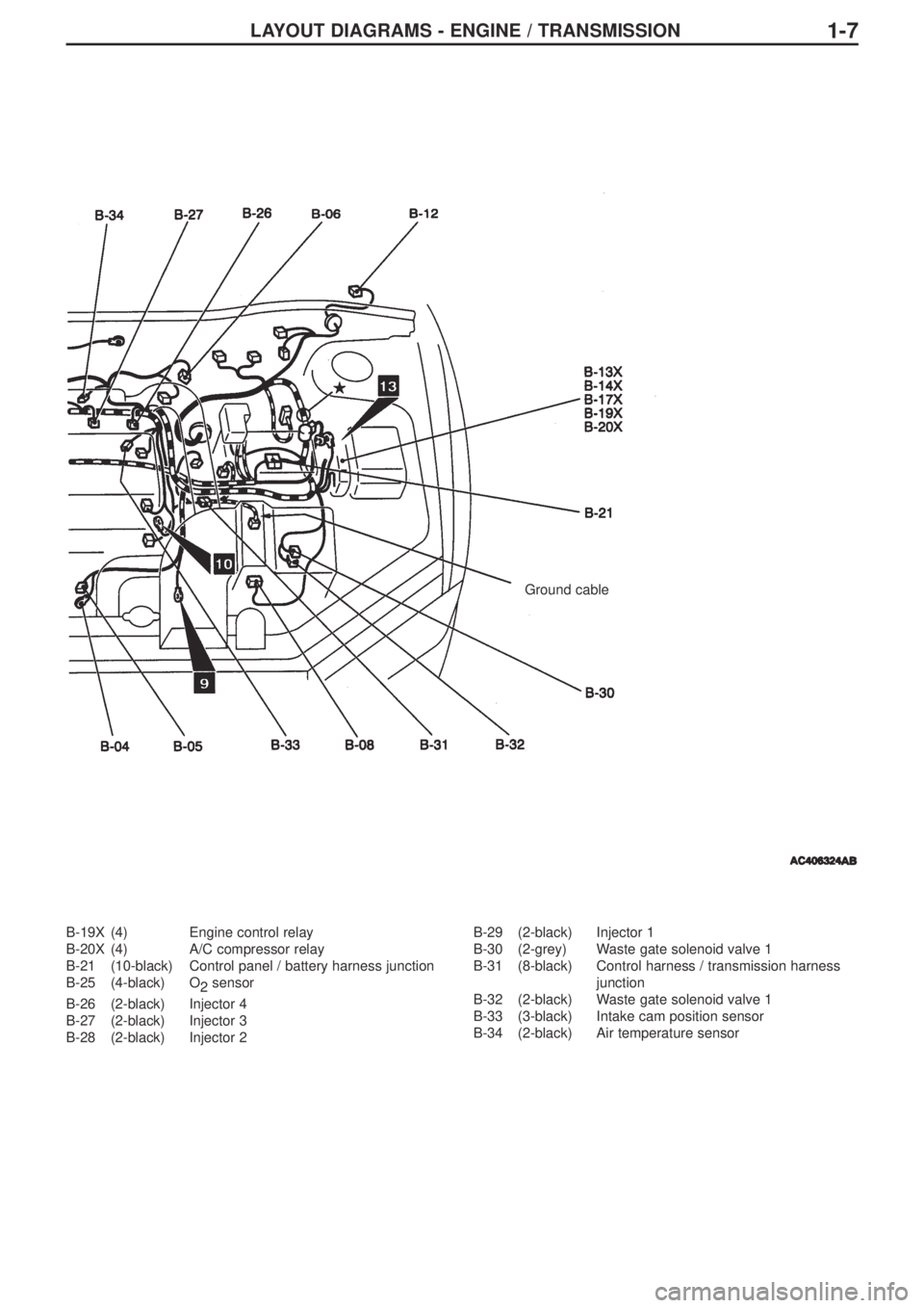
B-19X (4) Engine control relay
B-20X (4) A/C compressor relay
B-21 (10-black) Control panel / battery harness junction
B-25 (4-black) O
2sensor
B-26 (2-black) Injector 4
B-27 (2-black) Injector 3
B-28 (2-black) Injector 2B-29 (2-black) Injector 1
B-30 (2-grey) Waste gate solenoid valve 1
B-31 (8-black) Control harness / transmission harness
junction
B-32 (2-black) Waste gate solenoid valve 1
B-33 (3-black) Intake cam position sensor
B-34 (2-black) Air temperature sensor
LAYOUT DIAGRAMS - ENGINE / TRANSMISSION
Ground cable
Page 158 of 364
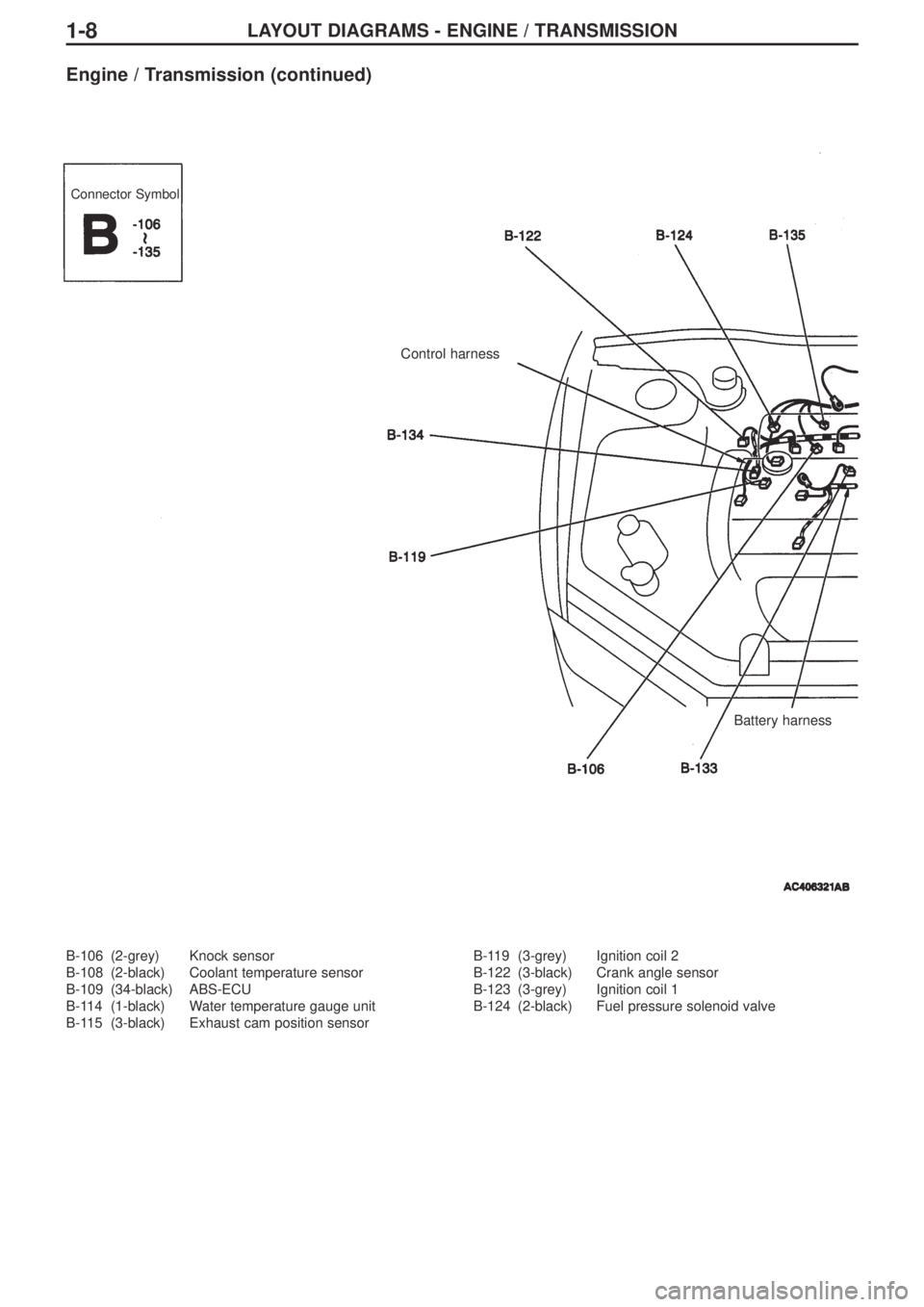
LAYOUT DIAGRAMS - ENGINE / TRANSMISSION1-8
B-106 (2-grey) Knock sensor
B-108 (2-black) Coolant temperature sensor
B-109 (34-black) ABS-ECU
B-114 (1-black) Water temperature gauge unit
B-115 (3-black) Exhaust cam position sensorB-119 (3-grey) Ignition coil 2
B-122 (3-black) Crank angle sensor
B-123 (3-grey) Ignition coil 1
B-124 (2-black) Fuel pressure solenoid valve
Engine / Transmission (continued)
Connector Symbol
Control harness
Battery harness
Page 181 of 364
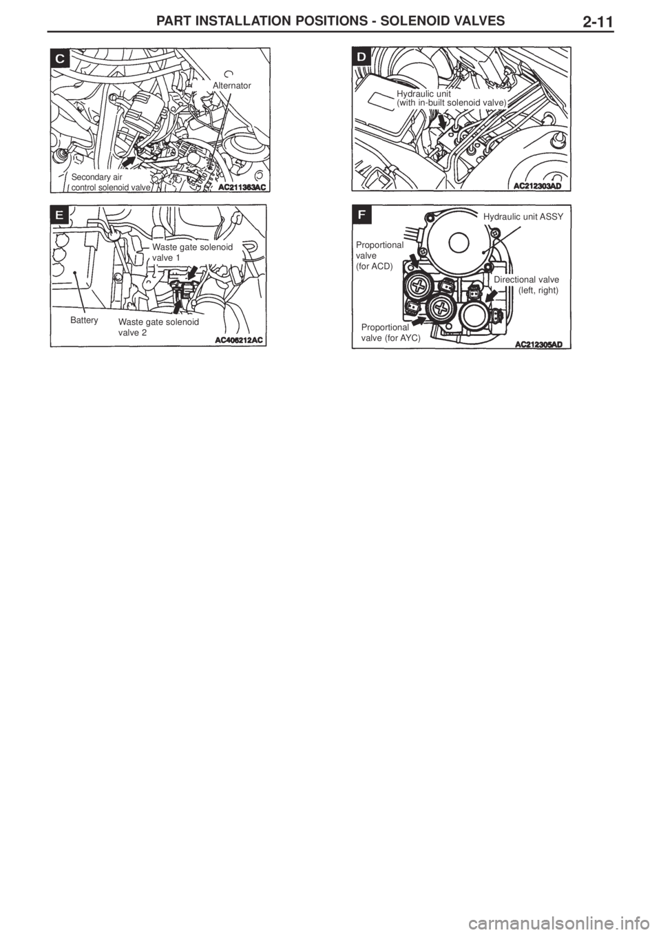
PART INSTALLATION POSITIONS - SOLENOID VALVES2-11
Alternator
Secondary air
control solenoid valve
Hydraulic unit
(with in-built solenoid valve)
Waste gate solenoid
valve 1
Waste gate solenoid
valve 2 Battery Hydraulic unit ASSY
Proportional
valve
(for ACD)
Proportional
valve (for AYC)Directional valve
(left, right)
Page 198 of 364
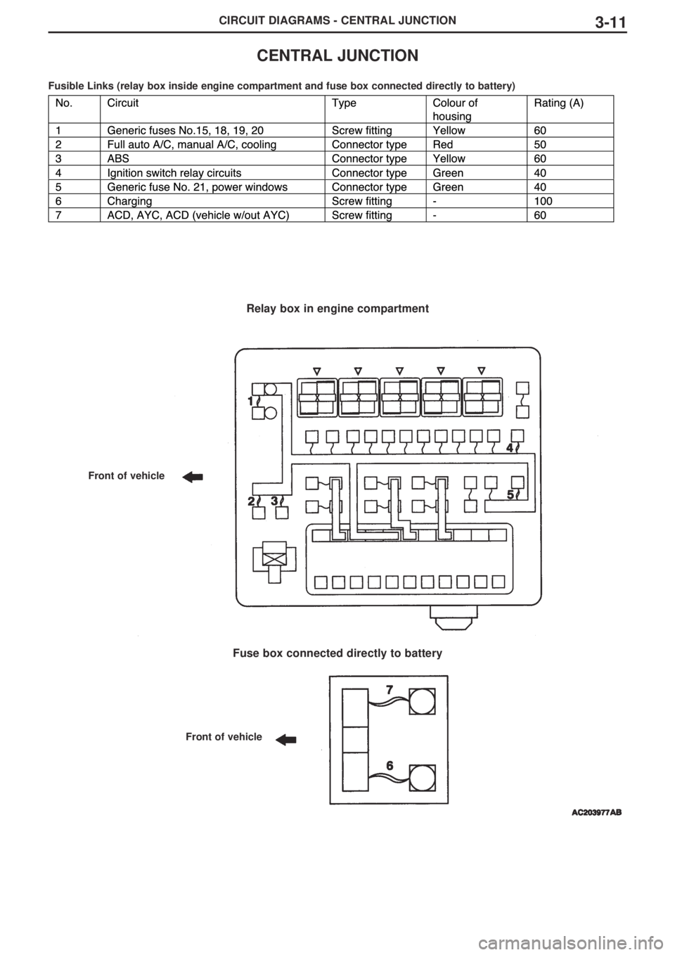
CIRCUIT DIAGRAMS - CENTRAL JUNCTION3-11
CENTRAL JUNCTION
Fusible Links (relay box inside engine compartment and fuse box connected directly to battery)
Relay box in engine compartment
Fuse box connected directly to battery
Front of vehicle
Front of vehicle
Page 205 of 364
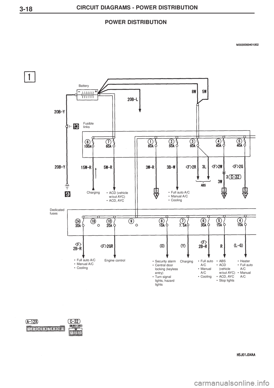
3-18CIRCUIT DIAGRAMS - POWER DISTRIBUTION
Battery
Fusible
links
Charging
Charging •ACD (vehicle
w/out AYC)
•ACD, AYC•Full auto A/C
•Manual A/C
•Cooling
Dedicated
fuses
•Full auto A/C
•Manual A/C
•CoolingEngine control
•Security alarm
•Central door
locking (keyless
entry)
•Turn signal
lights, hazard
lights•Full auto
A/C
•Manual
A/C
•Cooling•ABS
•ACD
(vehicle
w/out AYC)
•ACD, AYC
•Stop lights•Heater
•Full auto
A/C
•Manual
A/C
POWER DISTRIBUTION
Page 210 of 364
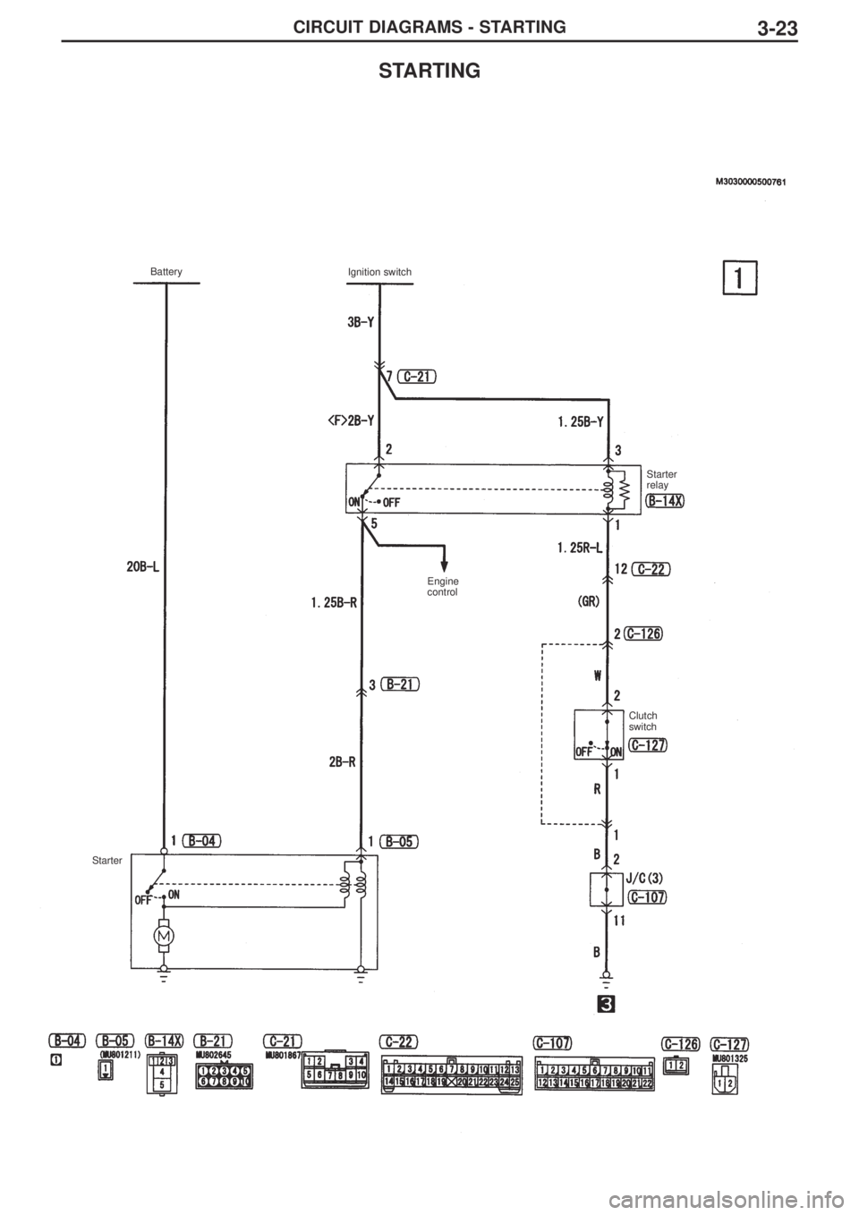
CIRCUIT DIAGRAMS - STARTING3-23
STARTING
Battery
Ignition switch
Engine
controlStarter
relay
Clutch
switch
Starter