fuse diagram MITSUBISHI LANCER EVOLUTION IX 2005 Workshop Manual
[x] Cancel search | Manufacturer: MITSUBISHI, Model Year: 2005, Model line: LANCER EVOLUTION IX, Model: MITSUBISHI LANCER EVOLUTION IX 2005Pages: 364, PDF Size: 14.38 MB
Page 142 of 364
GENERAL INFORMATION - HOW TO READ THE WIRING DIAGRAMS0-4
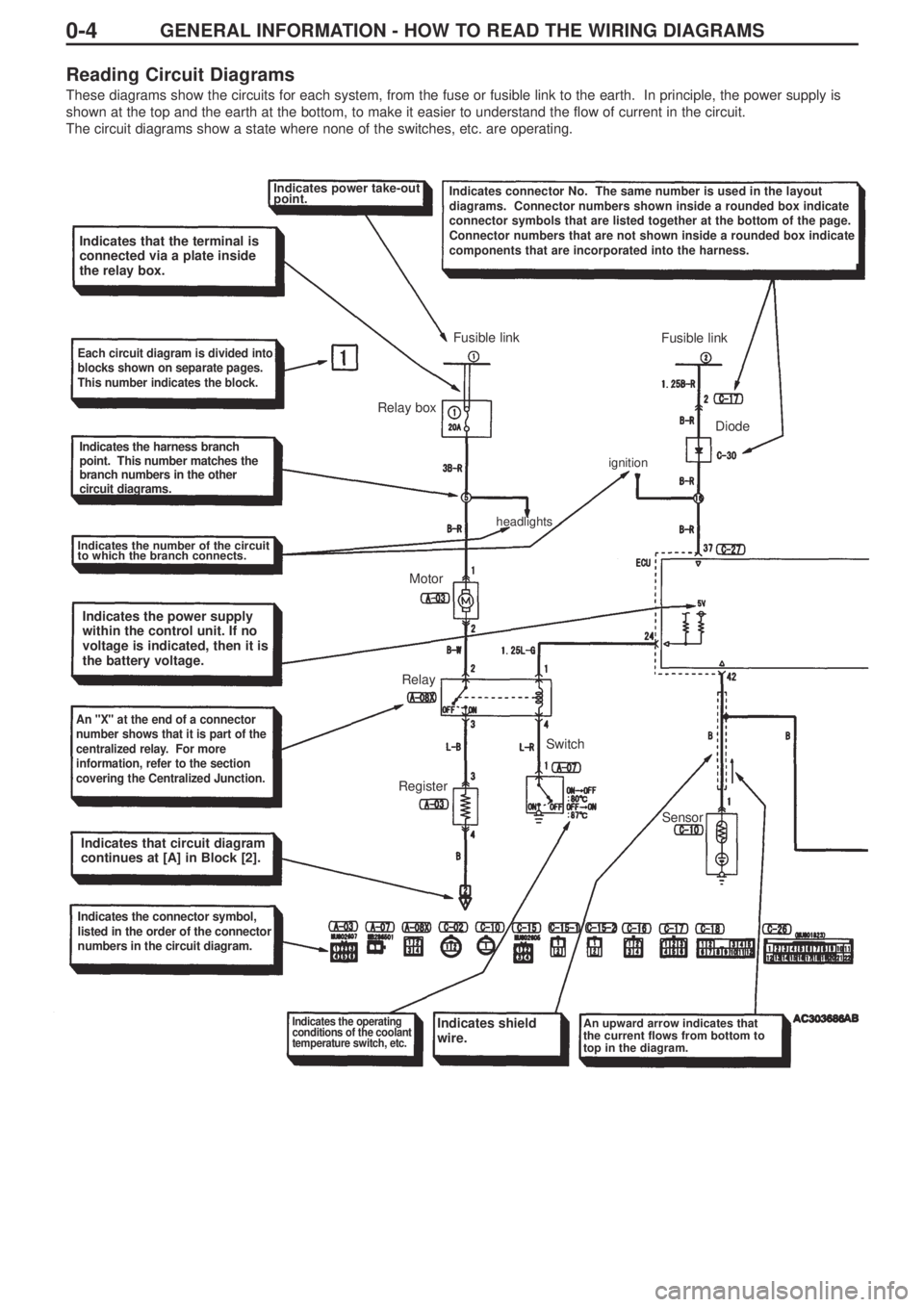
Reading Circuit Diagrams
These diagrams show the circuits for each system, from the fuse or fusible link to the earth. In principle, the power supply is
shown at the top and the earth at the bottom, to make it easier to understand the flow of current in the circuit.
The circuit diagrams show a state where none of the switches, etc. are operating.
Indicates power take-out
point.Indicates connector No. The same number is used in the layout
diagrams. Connector numbers shown inside a rounded box indicate
connector symbols that are listed together at the bottom of the page.
Connector numbers that are not shown inside a rounded box indicate
components that are incorporated into the harness.
Indicates that the terminal is
connected via a plate inside
the relay box.
Each circuit diagram is divided into
blocks shown on separate pages.
This number indicates the block.
Indicates the harness branch
point. This number matches the
branch numbers in the other
circuit diagrams.
Indicates the number of the circuit
to which the branch connects.
Indicates the power supply
within the control unit. If no
voltage is indicated, then it is
the battery voltage.
An "X" at the end of a connector
number shows that it is part of the
centralized relay. For more
information, refer to the section
covering the Centralized Junction.
Indicates that circuit diagram
continues at [A] in Block [2].
Indicates the connector symbol,
listed in the order of the connector
numbers in the circuit diagram.
Indicates the operating
conditions of the coolant
temperature switch, etc.Indicates shield
wire.An upward arrow indicates that
the current flows from bottom to
top in the diagram.
RegisterRelayMotor Relay boxFusible link
Fusible link
Diode
Sensor Switch
headlightsignition
Page 165 of 364
LAYOUT DIAGRAMS - INSTRUMENT PANEL1-15
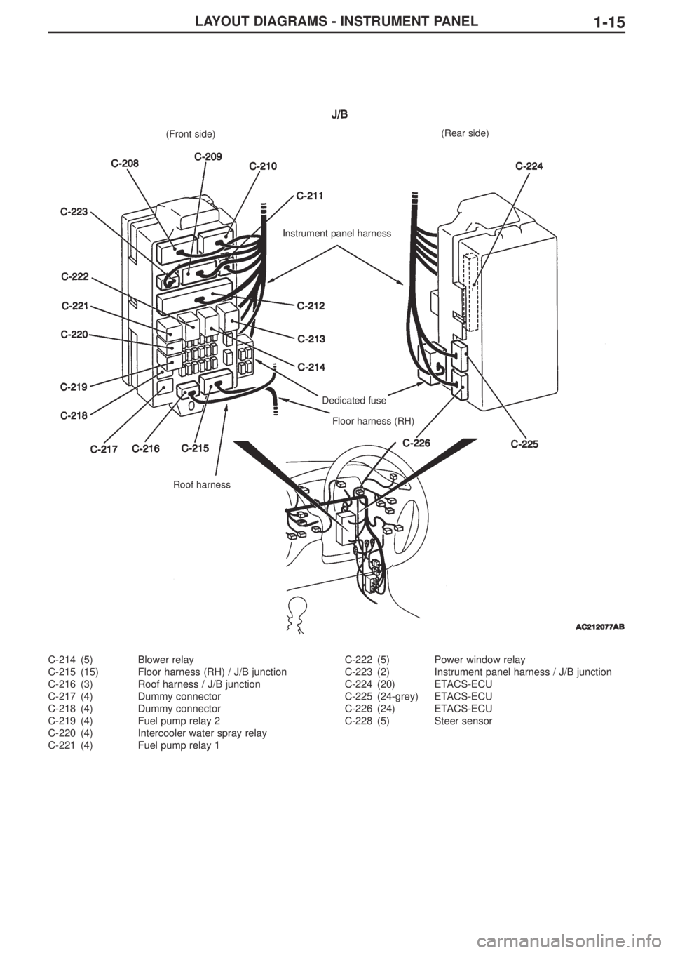
C-214 (5) Blower relay
C-215 (15) Floor harness (RH) / J/B junction
C-216 (3) Roof harness / J/B junction
C-217 (4) Dummy connector
C-218 (4) Dummy connector
C-219 (4) Fuel pump relay 2
C-220 (4) Intercooler water spray relay
C-221 (4) Fuel pump relay 1C-222 (5) Power window relay
C-223 (2) Instrument panel harness / J/B junction
C-224 (20) ETACS-ECU
C-225 (24-grey) ETACS-ECU
C-226 (24) ETACS-ECU
C-228 (5) Steer sensor
(Front side)
Instrument panel harness
Dedicated fuse
Floor harness (RH)
Roof harness(Rear side)
Page 191 of 364
CIRCUIT DIAGRAMS - J/B3-4
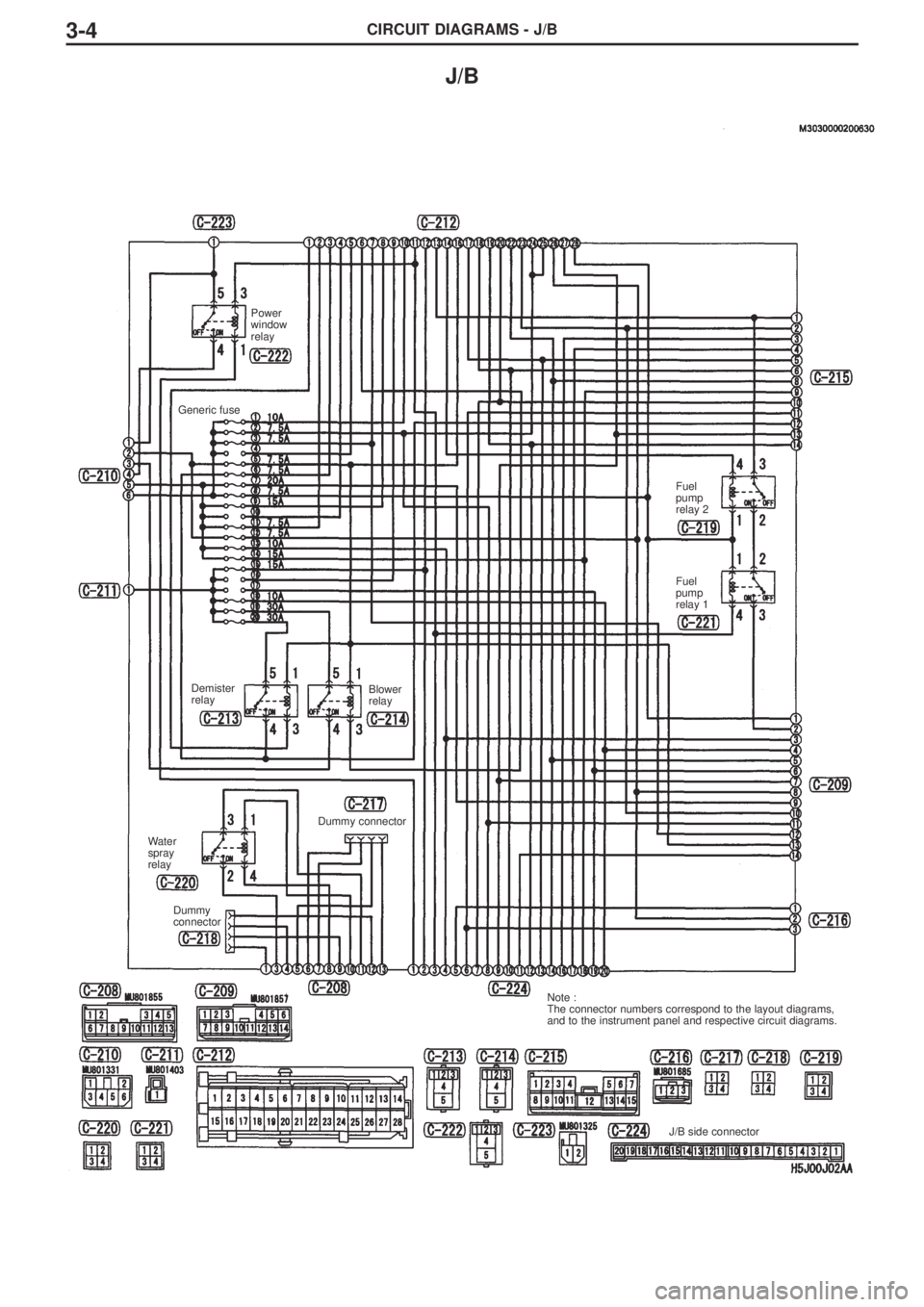
J/B
Power
window
relay
Water
spray
relay
Dummy
connectorDummy connector
J/B side connector Note :
The connector numbers correspond to the layout diagrams,
and to the instrument panel and respective circuit diagrams. Demister
relayBlower
relayFuel
pump
relay 2
Fuel
pump
relay 1 Generic fuse
Page 192 of 364
CIRCUIT DIAGRAMS - J/B3-5
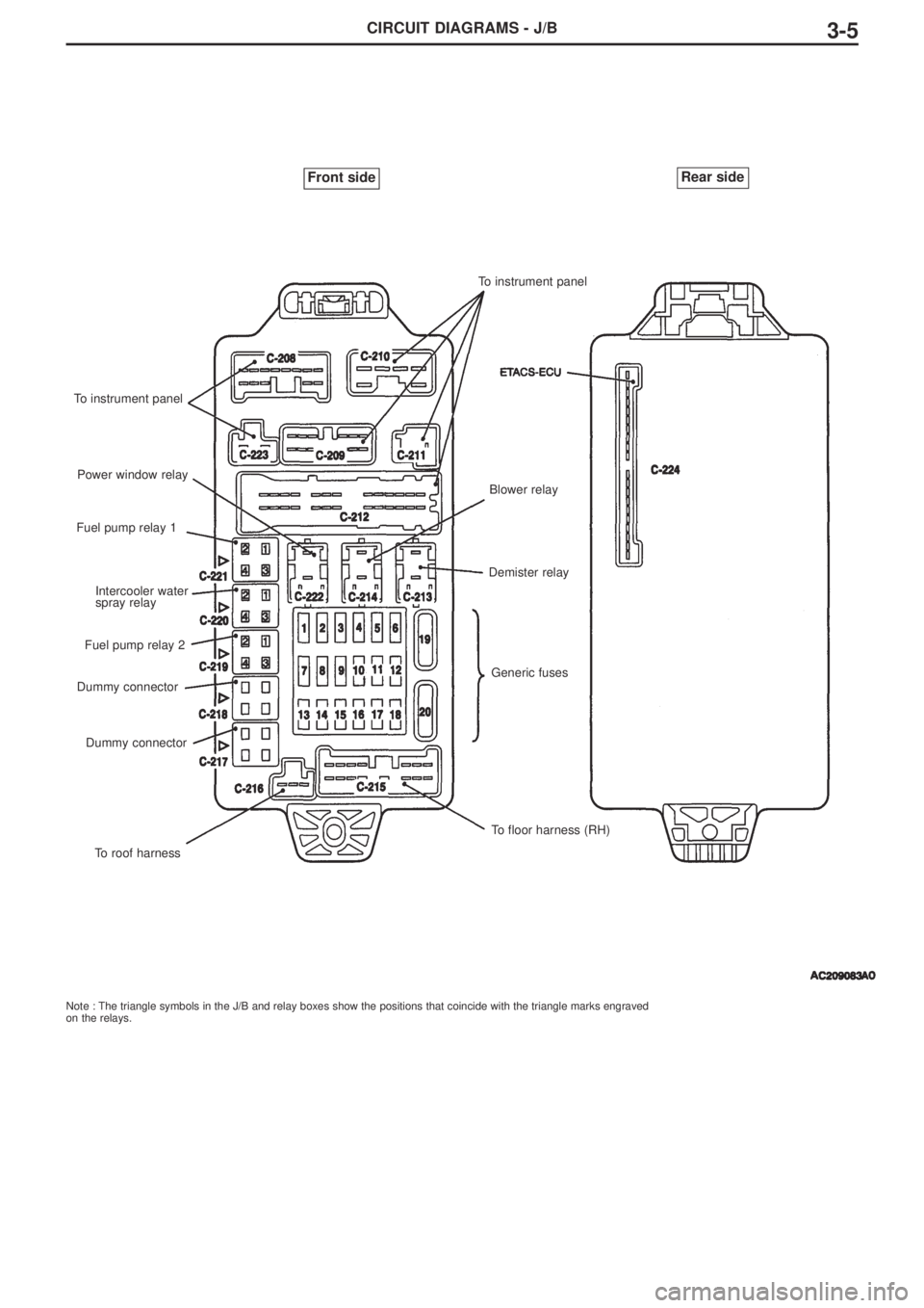
Note : The triangle symbols in the J/B and relay boxes show the positions that coincide with the triangle marks engraved
on the relays.
Front sideRear side
To instrument panel
Power window relay
Fuel pump relay 1
Intercooler water
spray relay
Fuel pump relay 2
Dummy connector
Dummy connector
To roof harnessTo instrument panel
Blower relay
Demister relay
Generic fuses
To floor harness (RH)
Page 193 of 364
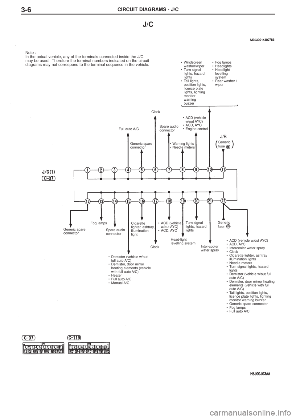
CIRCUIT DIAGRAMS - J/C3-6
J/C
Note :
In the actual vehicle, any of the terminals connected inside the J/C
may be used. Therefore the terminal numbers indicated on the circuit
diagrams may not correspond to the terminal sequence in the vehicle.
• Windscreen
washer/wiper
• Turn signal
lights, hazard
lights
• Tail lights,
position lights,
licence plate
lights, lighting
monitor
warning
buzzer•Fog lamps
•Headlights
•Headlight
levelling
system
•Rear washer /
wiper
Full auto A/C
Generic spare
connector
Generic spare
connectorFog lamps
Spare audio
connector
• Demister (vehicle w/out
full auto A/C)
• Demister, door mirror
heating elements (vehicle
with full auto A/C)
• Heater
• Full auto A/C
• Manual A/CCigarette
lighter, ashtray,
illumination
light
Clock• ACD (vehicle
w/out AYC)
• ACD, AYC
Head-light
levelling systemTurn signal
lights, hazard
lights
Inter-cooler
water spray• ACD (vehicle w/out AYC)
• ACD, AYC
• Intercooler water spray
• Clock
• Cigarette lighter, ashtray
illumination lights
• Needle meters
• Turn signal lights, hazard
lights
• Demister (vehicle w/out full
auto A/C)
• Demister, door mirror heating
elements (vehicle with full
auto A/C)
• Tail lights, position lights,
licence plate lights, lighting
monitor warning buzzer
• Generic spare connector
• Fog lamps
• Full auto A/C Clock
Spare audio
connector• ACD (vehicle
w/out AYC)
• ACD, AYC
• Engine control
• Warning lights
• Needle metersGeneric
fuse
J/B
(
)
Generic
fuse
Page 194 of 364
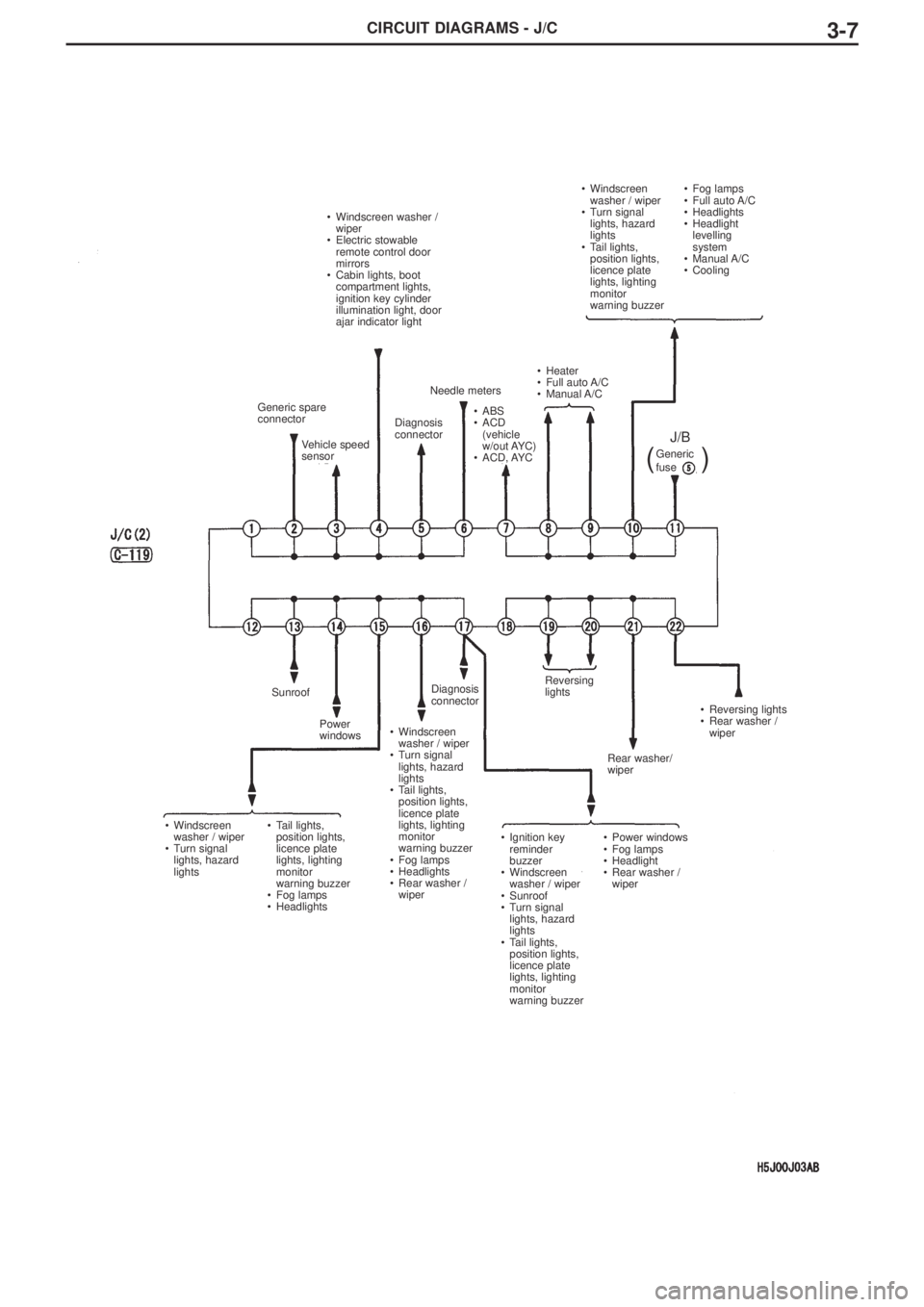
CIRCUIT DIAGRAMS - J/C3-7
• Windscreen
washer / wiper
• Turn signal
lights, hazard
lights
• Tail lights,
position lights,
licence plate
lights, lighting
monitor
warning buzzer•Fog lamps
•Full auto A/C
•Headlights
•Headlight
levelling
system
•Manual A/C
•Cooling
• Windscreen
washer / wiper
• Turn signal
lights, hazard
lights• Tail lights,
position lights,
licence plate
lights, lighting
monitor
warning buzzer
• Fog lamps
• Headlights• Ignition key
reminder
buzzer
• Windscreen
washer / wiper
• Sunroof
• Turn signal
lights, hazard
lights
• Tail lights,
position lights,
licence plate
lights, lighting
monitor
warning buzzer• Power windows
• Fog lamps
• Headlight
• Rear washer /
wiper Generic spare
connector
Vehicle speed
sensor• Windscreen washer /
wiper
• Electric stowable
remote control door
mirrors
• Cabin lights, boot
compartment lights,
ignition key cylinder
illumination light, door
ajar indicator light
Diagnosis
connector• ABS
• ACD
(vehicle
w/out AYC)
• ACD, AYC Needle meters• Heater
• Full auto A/C
• Manual A/C
J/B
Sunroof
Power
windows• Windscreen
washer / wiper
• Turn signal
lights, hazard
lights
• Tail lights,
position lights,
licence plate
lights, lighting
monitor
warning buzzer
• Fog lamps
• Headlights
• Rear washer /
wiperDiagnosis
connectorReversing
lights
Rear washer/
wiper• Reversing lights
• Rear washer /
wiper Generic
fuse
(
)
Page 196 of 364
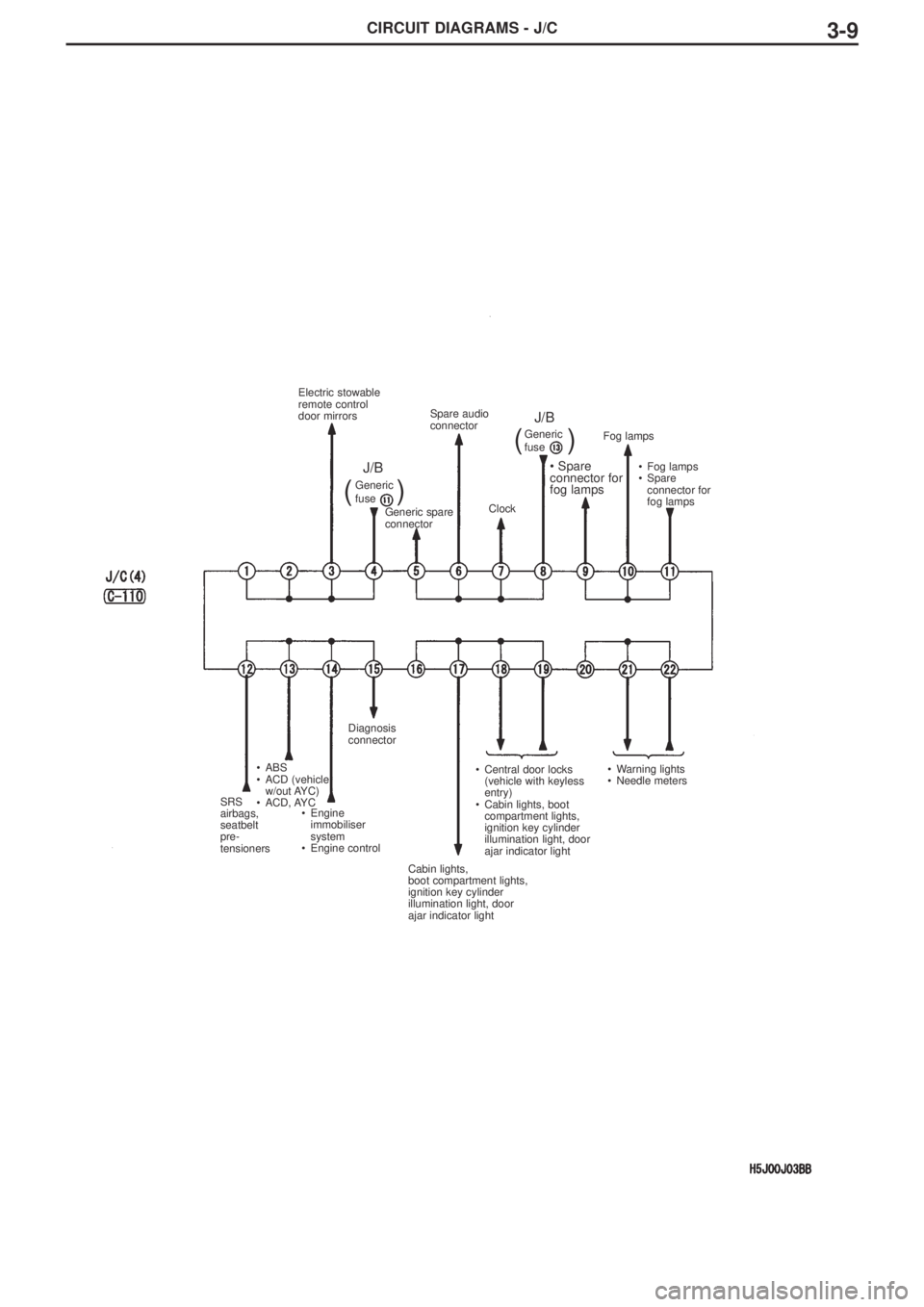
CIRCUIT DIAGRAMS - J/C3-9
SRS
airbags,
seatbelt
pre-
tensioners•ABS
•ACD (vehicle
w/out AYC)
•ACD, AYC
•Engine
immobiliser
system
•Engine controlDiagnosis
connector
Cabin lights,
boot compartment lights,
ignition key cylinder
illumination light, door
ajar indicator light•Central door locks
(vehicle with keyless
entry)
•Cabin lights, boot
compartment lights,
ignition key cylinder
illumination light, door
ajar indicator light•Warning lights
•Needle meters•Fog lamps
•Spare
connector for
fog lamps Fog lamps
• Spare
connector for
fog lamps
Clock Spare audio
connector
Generic spare
connector Electric stowable
remote control
door mirrors
Generic
fuseGeneric
fuse
J/BJ/B
((
))
Page 198 of 364
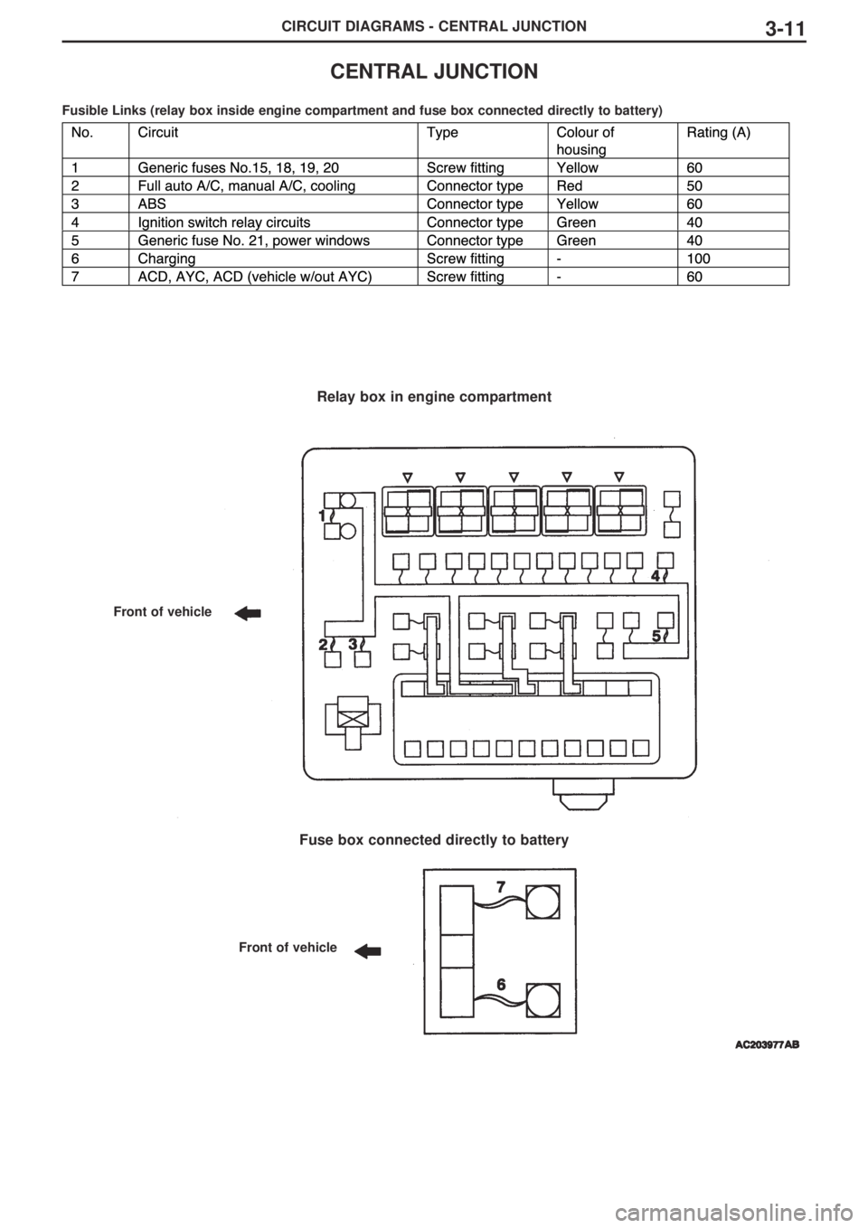
CIRCUIT DIAGRAMS - CENTRAL JUNCTION3-11
CENTRAL JUNCTION
Fusible Links (relay box inside engine compartment and fuse box connected directly to battery)
Relay box in engine compartment
Fuse box connected directly to battery
Front of vehicle
Front of vehicle
Page 199 of 364
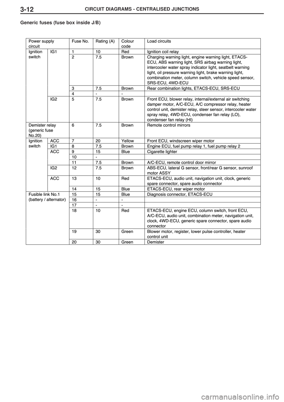
CIRCUIT DIAGRAMS - CENTRALISED JUNCTIONS3-12
Generic fuses (fuse box inside J/B)
Page 200 of 364
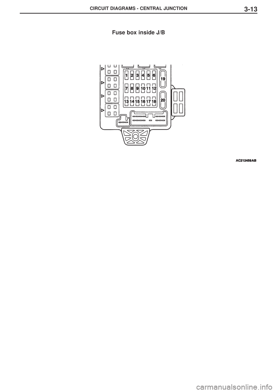
CIRCUIT DIAGRAMS - CENTRAL JUNCTION3-13
Fuse box inside J/B