sensor MITSUBISHI LANCER EVOLUTION IX 2005 Owner's Manual
[x] Cancel search | Manufacturer: MITSUBISHI, Model Year: 2005, Model line: LANCER EVOLUTION IX, Model: MITSUBISHI LANCER EVOLUTION IX 2005Pages: 364, PDF Size: 14.38 MB
Page 57 of 364
13A-17MPI – TROUBLESHOOTING
*: Refer to the 01-1 Service Manual for the Lancer Evolution VIII (No.1036K02)
*: Refer to the 03-1 Service Manual for the Lancer Evolution VIII (No.1036K07)
Repair
Repair
Repair
Repair
Repair
Repair
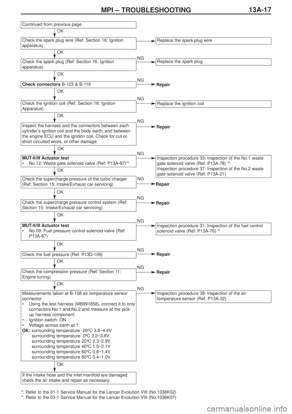
Continued from previous page
Replace the spark plug wire
Replace the spark plug
Replace the ignition coil
Inspection procedure 33: Inspection of the No.1 waste
gate solenoid valve (Ref: P13A-78) *2
Inspection procedure 37: Inspection of the No.2 waste
gate solenoid valve (Ref: P13A-21)
Inspection procedure 31: Inspection of the fuel control
solenoid valve (Ref: P13A-76) *2
Inspection procedure 38: Inspection of the air
temperature sensor (Ref: P13A-22)
Check the spark plug wire (Ref: Section 16: Ignition
apparatus)
Check the spark plug (Ref: Section 16: Ignition
apparatus)
Check connectors B-123 & B-119
Check the ignition coil (Ref: Section 16: Ignition
Apparatus)
Inspect the harness and the connectors between each
cylinder’s ignition coil and the body earth, and between
the engine ECU and the ignition coil. Check for cut or
short circuited wires, or other damage.
MUT-II/III Actuator test
•No.12: Waste gate solenoid valve (Ref: P13A-87)*2
Check the supercharge pressure of the turbo charger
(Ref: Section 15: Intake/Exhaust car servicing)
Check the supercharge pressure control system (Ref:
Section 15: Intake/Exhaust car servicing)
MUT-II/III Actuator test
•No.09: Fuel pressure control solenoid valve (Ref:
P13A-87)
Check the fuel pressure (Ref: P13D-109)
Check the compression pressure (Ref: Section 11:
Engine tuning)
If the intake hose and the inlet manifold are damaged
check the air intake and repair as necessary.
Measurements taken at B-108 air temperature sensor
connector
•Using the test harness (MB991658), connect it to only
connectors No.1 and No.2 and measure at the pick-
up harness component.
•Ignition switch: ON
•Voltage across earth at 1
OK:surrounding temperature -20ºC 3.8~4.4V
surrounding temperature 0ºC 3.2~3.8V
surrounding temperature 20ºC 2.3~2.9V
surrounding temperature 40ºC 1.5~2.1V
surrounding temperature 60ºC 0.8~1.4V
surrounding temperature 80ºC 0.4~1.0V
OK
OK
OK
OK
OK
OK
OK
OK
OK
OK
OK
OK
OK
NG
NG
NG
NG
NG
NG
NG
NG
NG
NG
NG
Page 58 of 364
13A-18MPI – TROUBLESHOOTING
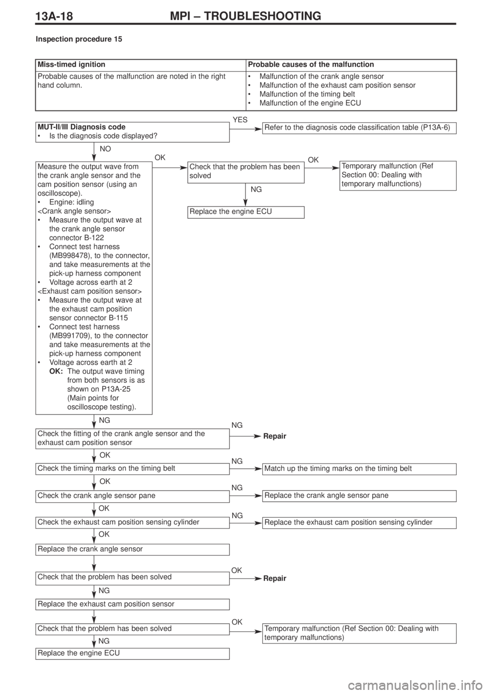
Measure the output wave from
the crank angle sensor and the
cam position sensor (using an
oscilloscope).
•Engine: idling
•Measure the output wave at
the crank angle sensor
connector B-122
•Connect test harness
(MB998478), to the connector,
and take measurements at the
pick-up harness component
•Voltage across earth at 2
•Measure the output wave at
the exhaust cam position
sensor connector B-115
•Connect test harness
(MB991709), to the connector
and take measurements at the
pick-up harness component
•Voltage across earth at 2
OK:The output wave timing
from both sensors is as
shown on P13A-25
(Main points for
oscilloscope testing).Check that the problem has been
solvedTemporary malfunction (Ref
Section 00: Dealing with
temporary malfunctions)
Replace the engine ECU
NO
OK
NG
OK
NG
NG
NG
Repair
Miss-timed ignitionProbable causes of the malfunction
Probable causes of the malfunction are noted in the right
hand column.•Malfunction of the crank angle sensor
•Malfunction of the exhaust cam position sensor
•Malfunction of the timing belt
•Malfunction of the engine ECU
Inspection procedure 15
Refer to the diagnosis code classification table (P13A-6)MUT-II/III Diagnosis code
•Is the diagnosis code displayed?YES
Repair
Replace the crank angle sensor pane
Match up the timing marks on the timing belt
Replace the exhaust cam position sensing cylinder
Temporary malfunction (Ref Section 00: Dealing with
temporary malfunctions)
Check the exhaust cam position sensing cylinder
Check the fitting of the crank angle sensor and the
exhaust cam position sensor
Check the timing marks on the timing belt
Check the crank angle sensor pane
Replace the crank angle sensor
Check that the problem has been solved
Replace the exhaust cam position sensor
Check that the problem has been solved
Replace the engine ECU
OK
OK
OK
NG
OK
NG
NG
NG
OK
OK
Page 62 of 364
13A-22MPI – TROUBLESHOOTING
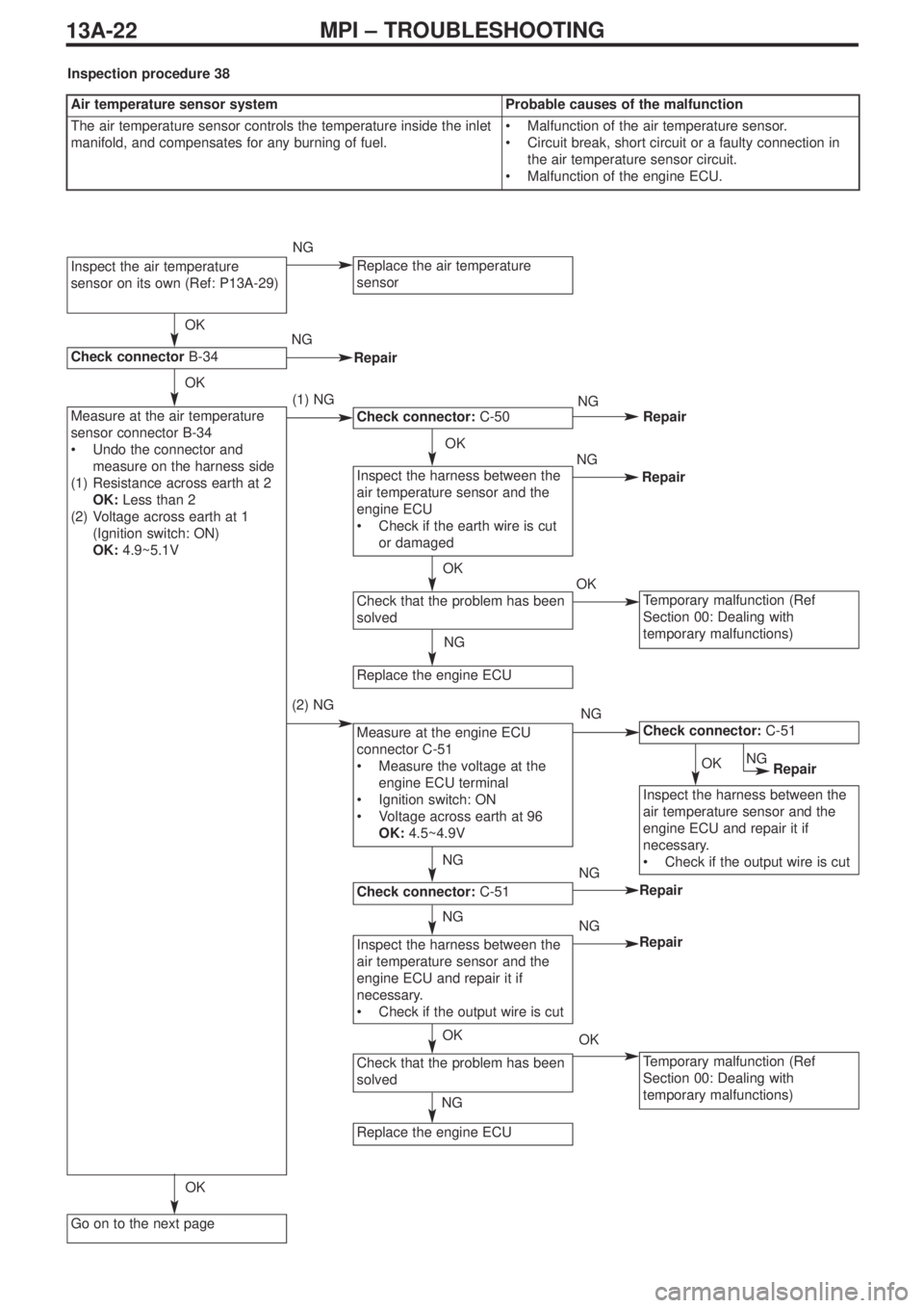
Inspect the air temperature
sensor on its own (Ref: P13A-29)
Check connectorB-34
Measure at the air temperature
sensor connector B-34
•Undo the connector and
measure on the harness side
(1) Resistance across earth at 2
OK:Less than 2Ω
(2) Voltage across earth at 1
(Ignition switch: ON)
OK:4.9~5.1V
Go on to the next page
Replace the air temperature
sensor
Temporary malfunction (Ref
Section 00: Dealing with
temporary malfunctions)
Measure at the engine ECU
connector C-51
•Measure the voltage at the
engine ECU terminal
•Ignition switch: ON
•Voltage across earth at 96
OK:4.5~4.9V
Replace the engine ECU
Check that the problem has been
solved
Inspect the harness between the
air temperature sensor and the
engine ECU
•Check if the earth wire is cut
or damaged
Check connector:C-50
Inspect the harness between the
air temperature sensor and the
engine ECU and repair it if
necessary.
•Check if the output wire is cut
Check connector:C-51
Temporary malfunction (Ref
Section 00: Dealing with
temporary malfunctions)
Check connector:C-51
Check that the problem has been
solved
Replace the engine ECU
Inspect the harness between the
air temperature sensor and the
engine ECU and repair it if
necessary.
•Check if the output wire is cut
OKNG
(1) NG
(2) NG
NG
OK
OK
NG
NG
NG
OK
NG
OK
OK
OK
NG
NG
NG
NG
NG
OK
Repair
Repair
Repair
Repair
Repair
Air temperature sensor systemProbable causes of the malfunction
The air temperature sensor controls the temperature inside the inlet
manifold, and compensates for any burning of fuel.•Malfunction of the air temperature sensor.
•Circuit break, short circuit or a faulty connection in
the air temperature sensor circuit.
•Malfunction of the engine ECU.
Inspection procedure 38
OKNGRepair
Page 63 of 364
13A-23MPI – TROUBLESHOOTING
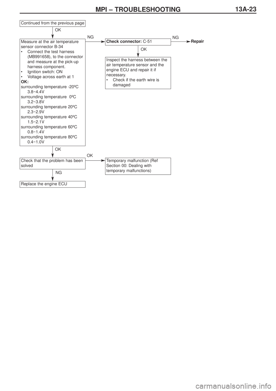
Continued from the previous page
Measure at the air temperature
sensor connector B-34
•Connect the test harness
(MB991658), to the connector
and measure at the pick-up
harness component.
•Ignition switch: ON
•Voltage across earth at 1
OK:
surrounding temperature -20ºC
3.8~4.4V
surrounding temperature 0ºC
3.2~3.8V
surrounding temperature 20ºC
2.3~2.9V
surrounding temperature 40ºC
1.5~2.1V
surrounding temperature 60ºC
0.8~1.4V
surrounding temperature 80ºC
0.4~1.0V
Check that the problem has been
solved
Replace the engine ECU
Inspect the harness between the
air temperature sensor and the
engine ECU and repair it if
necessary.
•Check if the earth wire is
damaged
Check connector: C-51
Temporary malfunction (Ref
Section 00: Dealing with
temporary malfunctions)
OK
OK
OK
NG
NG
OK
NGRepair
Page 65 of 364
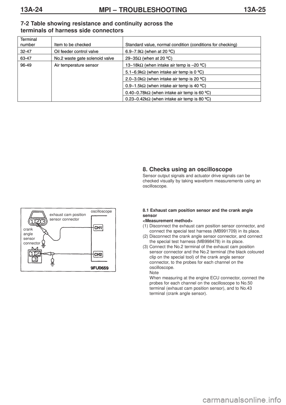
13A-25MPI – TROUBLESHOOTING 13A-24
7-2 Table showing resistance and continuity across the
terminals of harness side connectors
8. Checks using an oscilloscope
Sensor output signals and actuator drive signals can be
checked visually by taking waveform measurements using an
oscilloscope.
crank
angle
sensor
connectorexhaust cam position
sensor connector
oscilloscope8.1 Exhaust cam position sensor and the crank angle
sensor
(1) Disconnect the exhaust cam position sensor connector, and
connect the special test harness (MB991709) in its place.
(2) Disconnect the crank angle sensor connector, and connect
the special test harness (MB998478) in its place.
(3) Connect the No.2 terminal of the exhaust cam position
sensor connector and the No.2 terminal (the black coloured
clip on the special tool) of the crank angle sensor
connector, to the probes for each channel on the
oscilloscope.
Note
When measuring at the engine ECU connector, connect the
probes for each channel on the oscilloscope to No.50
terminal (exhaust cam position sensor), and to No.43
terminal (crank angle sensor).
Page 66 of 364
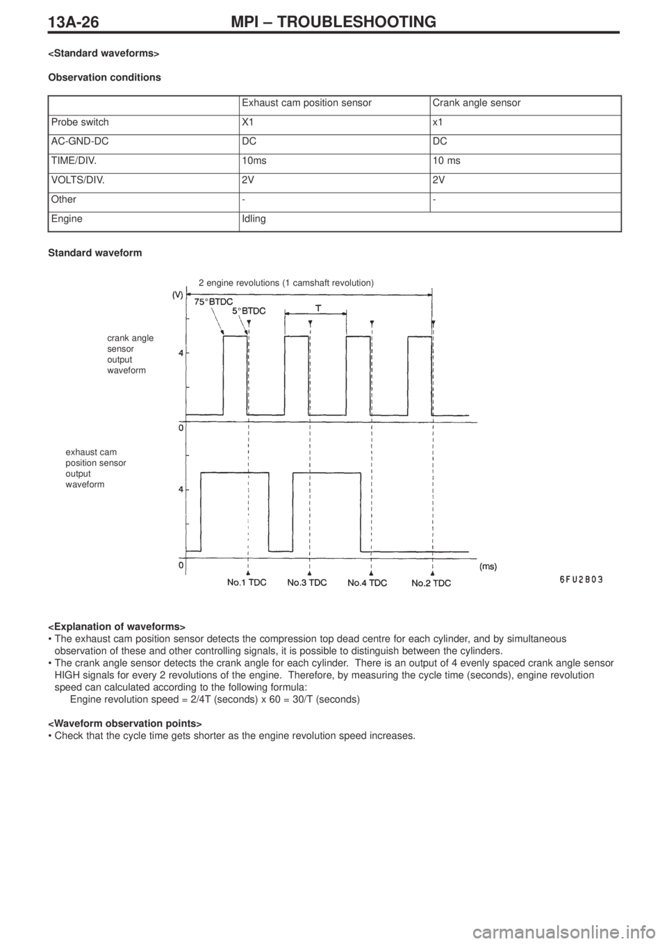
13A-26MPI – TROUBLESHOOTING
Observation conditions
Exhaust cam position sensorCrank angle sensor
Probe switchX1x1
AC-GND-DCDCDC
TIME/DIV.10ms10 ms
VOLTS/DIV.2V2V
Other--
EngineIdling
2 engine revolutions (1 camshaft revolution)
crank angle
sensor
output
waveform
exhaust cam
position sensor
output
waveform
Standard waveform
•The exhaust cam position sensor detects the compression top dead centre for each cylinder, and by simultaneous
observation of these and other controlling signals, it is possible to distinguish between the cylinders.
•The crank angle sensor detects the crank angle for each cylinder. There is an output of 4 evenly spaced crank angle sensor
HIGH signals for every 2 revolutions of the engine. Therefore, by measuring the cycle time (seconds), engine revolution
speed can calculated according to the following formula:
Engine revolution speed = 2/4T (seconds) x 60 = 30/T (seconds)
•Check that the cycle time gets shorter as the engine revolution speed increases.
Page 67 of 364
13A-27MPI – TROUBLESHOOTING
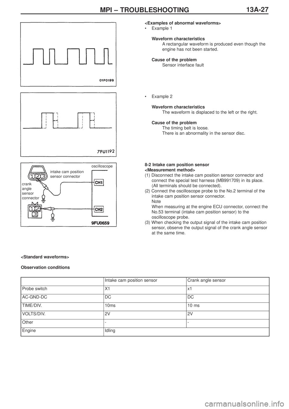
•Example 1
Waveform characteristics
Arectangular waveform is produced even though the
engine has not been started.
Cause of the problem
Sensor interface fault
•Example 2
Waveform characteristics
The waveform is displaced to the left or the right.
Cause of the problem
The timing belt is loose.
There is an abnormality in the sensor disc.
8-2 Intake cam position sensor
(1) Disconnect the intake cam position sensor connector and
connect the special test harness (MB991709) in its place.
(All terminals should be connected).
(2) Connect the oscilloscope probe to the No.2 terminal of the
intake cam position sensor connector.
Note
When measuring at the engine ECU connector, connect the
No.53 terminal (intake cam position sensor) to the
oscilloscope probe.
(3) When checking the output signal of the intake cam position
sensor, observe the output signal of the crank angle sensor
at the same time.
crank
angle
sensor
connector
intake cam position
sensor connectoroscilloscope
Observation conditions
Intake cam position sensorCrank angle sensor
Probe switchX1x1
AC-GND-DCDCDC
TIME/DIV.10ms10 ms
VOLTS/DIV.2V2V
Other--
EngineIdling
Page 68 of 364
13A-28MPI – TROUBLESHOOTING
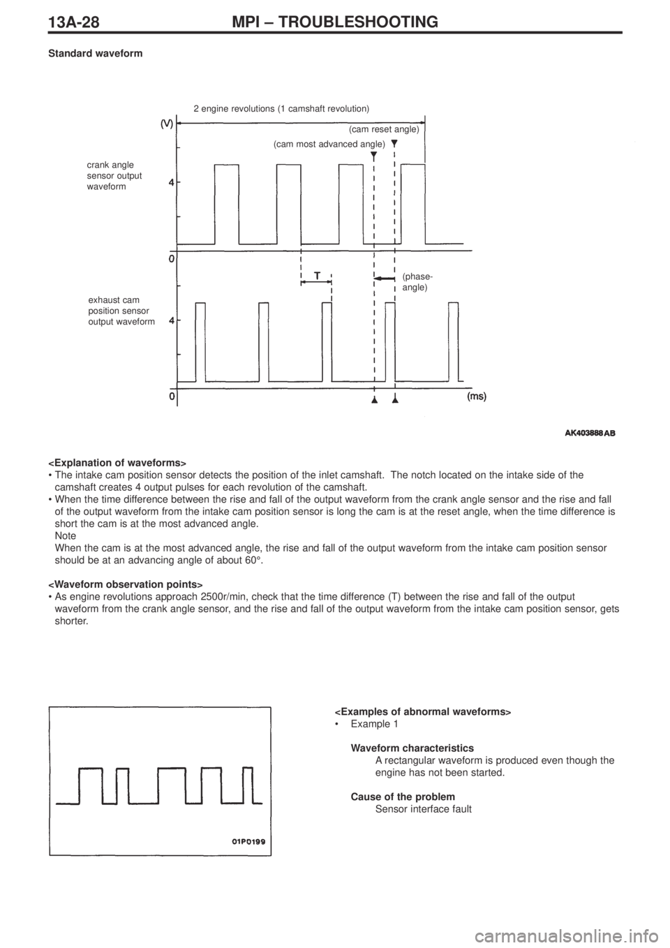
Standard waveform
2 engine revolutions (1 camshaft revolution)
crank angle
sensor output
waveform
exhaust cam
position sensor
output waveform(cam reset angle)
(cam most advanced angle)
(phase-
angle)
•The intake cam position sensor detects the position of the inlet camshaft. The notch located on the intake side of the
camshaft creates 4 output pulses for each revolution of the camshaft.
•When the time difference between the rise and fall of the output waveform from the crank angle sensor and the rise and fall
of the output waveform from the intake cam position sensor is long the cam is at the reset angle, when the time difference is
short the cam is at the most advanced angle.
Note
When the cam is at the most advanced angle, the rise and fall of the output waveform from the intake cam position sensor
should be at an advancing angle of about 60°.
•As engine revolutions approach 2500r/min, check that the time difference (T) between the rise and fall of the output
waveform from the crank angle sensor, and the rise and fall of the output waveform from the intake cam position sensor, gets
shorter.
•Example 1
Waveform characteristics
Arectangular waveform is produced even though the
engine has not been started.
Cause of the problem
Sensor interface fault
Page 69 of 364
13A-29MPI – TROUBLESHOOTING, ON-VEHICLE SERVICING
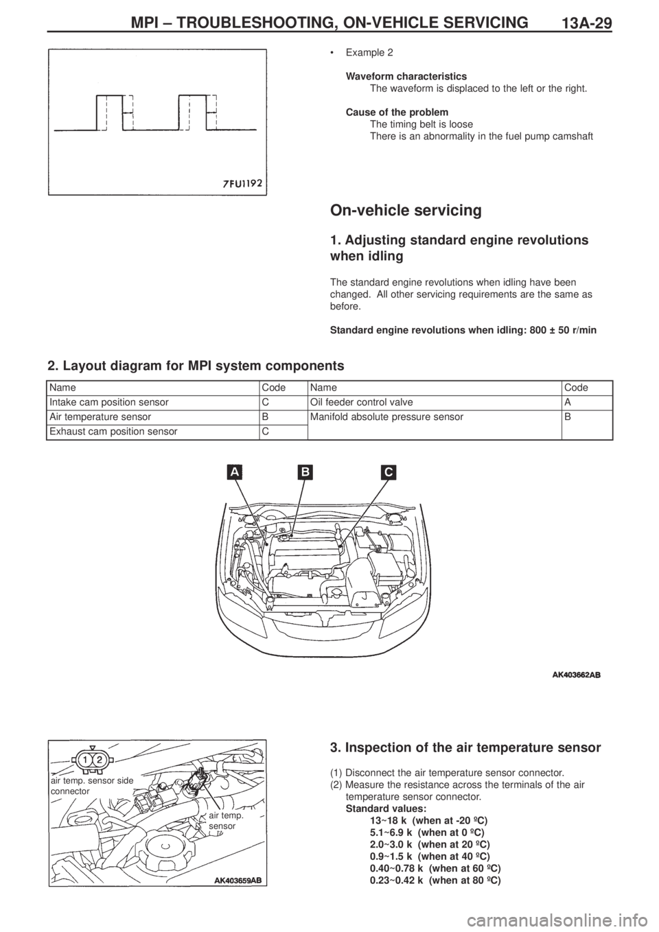
•Example 2
Waveform characteristics
The waveform is displaced to the left or the right.
Cause of the problem
The timing belt is loose
There is an abnormality in the fuel pump camshaft
On-vehicle servicing
1. Adjusting standard engine revolutions
when idling
The standard engine revolutions when idling have been
changed. All other servicing requirements are the same as
before.
Standard engine revolutions when idling: 800 ± 50 r/min
NameCodeNameCode
Intake cam position sensorCOil feeder control valveA
Air temperature sensorBManifold absolute pressure sensorB
Exhaust cam position sensorC
2. Layout diagram for MPI system components
air temp. sensor side
connector
air temp.
sensor
3. Inspection of the air temperature sensor
(1) Disconnect the air temperature sensor connector.
(2) Measure the resistance across the terminals of the air
temperature sensor connector.
Standard values:
13~18 kΩ (when at -20 ºC)
5.1~6.9 kΩ (when at 0 ºC)
2.0~3.0 kΩ (when at 20 ºC)
0.9~1.5 kΩ (when at 40 ºC)
0.40~0.78 kΩ (when at 60 ºC)
0.23~0.42 kΩ (when at 80 ºC)
Page 70 of 364
MPI – ON-VEHICLE SERVICING13A-30
(3) Remove the air temperature sensor
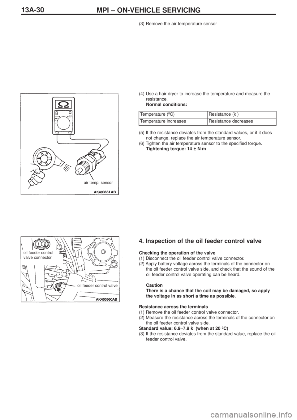
(4) Use a hair dryer to increase the temperature and measure the
resistance.
Normal conditions:
air temp. sensor
Temperature (ºC)Resistance (kΩ)
Temperature increasesResistance decreases
(5) If the resistance deviates from the standard values, or if it does
not change, replace the air temperature sensor.
(6) Tighten the air temperature sensor to the specified torque.
Tightening torque: 14 ± N·m
4. Inspection of the oil feeder control valve
Checking the operation of the valve
(1) Disconnect the oil feeder control valve connector.
(2) Apply battery voltage across the terminals of the connector on
the oil feeder control valve side, and check that the sound of the
oil feeder control valve operating can be heard.
Caution
There is a chance that the coil may be damaged, so apply
the voltage in as short a time as possible.
Resistance across the terminals
(1) Remove the oil feeder control valve connector.
(2) Measure the resistance across the terminals of the connector on
the oil feeder control valve side.
Standard value: 6.9~7.9 kΩ (when at 20 ºC)
(3) If the resistance deviates from the standard value, replace the oil
feeder control valve.oil feeder control
valve connector
oil feeder control valve