MITSUBISHI LANCER EVOLUTION IX 2005 Owner's Guide
LANCER EVOLUTION IX 2005
MITSUBISHI
MITSUBISHI
https://www.carmanualsonline.info/img/19/57323/w960_57323-0.png
MITSUBISHI LANCER EVOLUTION IX 2005 Owner's Guide
Page 211 of 364
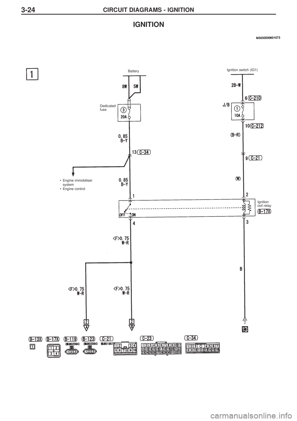
CIRCUIT DIAGRAMS - IGNITION3-24
IGNITION
BatteryIgnition switch (IG1)
Dedicated
fuse
Ignition
coil relay •Engine immobiliser
system
•Engine control
Page 212 of 364
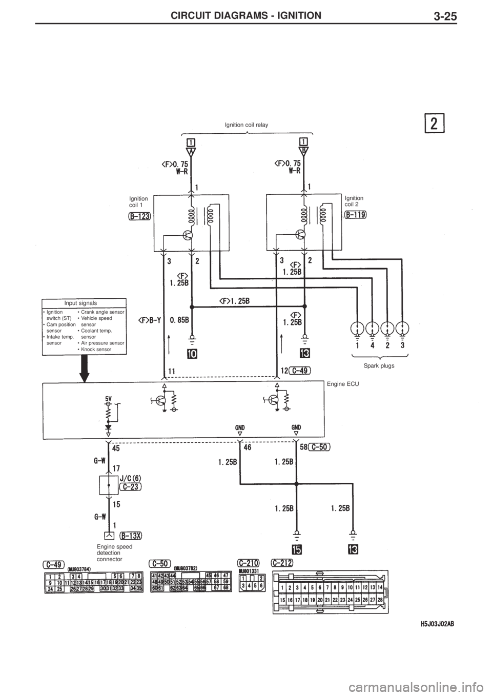
CIRCUIT DIAGRAMS - IGNITION3-25
Ignition coil relay
Ignition
coil 1Ignition
coil 2
Input signals
•Crank angle sensor
•Vehicle speed
sensor
•Coolant temp.
sensor
•Air pressure sensor
•Knock sensor •Ignition
switch (ST)
•Cam position
sensor
•Intake temp.
sensor
Spark plugs
Engine ECU
Engine speed
detection
connector
Page 215 of 364
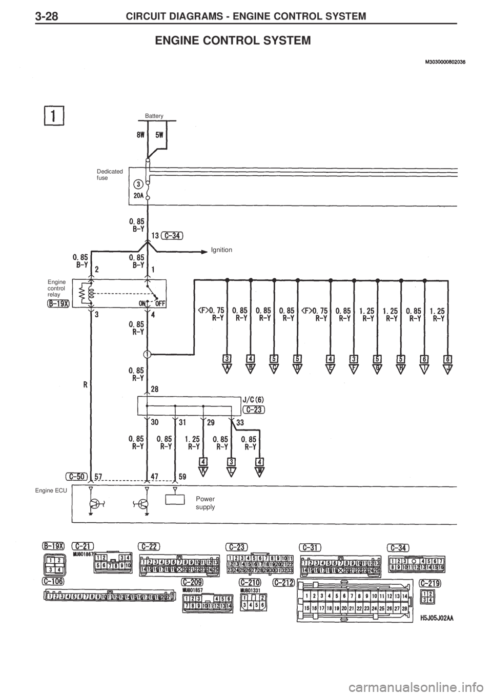
CIRCUIT DIAGRAMS - ENGINE CONTROL SYSTEM3-28
ENGINE CONTROL SYSTEM
Battery
Dedicated
fuse
Engine
control
relay
Engine ECU
Ignition
Power
supply
Page 216 of 364
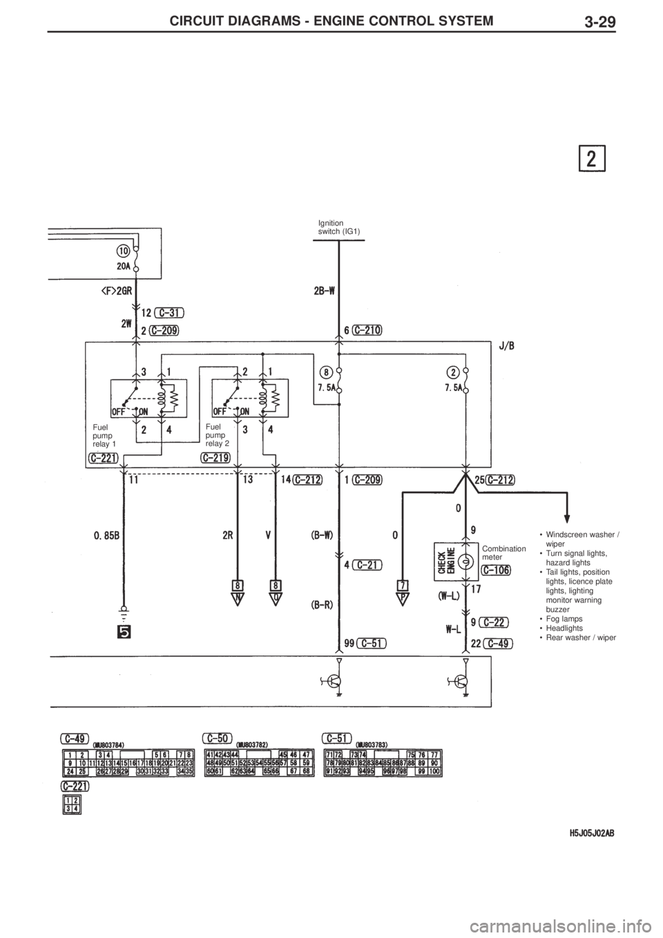
CIRCUIT DIAGRAMS - ENGINE CONTROL SYSTEM3-29
Ignition
switch (IG1)
Fuel
pump
relay 1Fuel
pump
relay 2
Combination
meter•Windscreen washer /
wiper
•Turn signal lights,
hazard lights
•Tail lights, position
lights, licence plate
lights, lighting
monitor warning
buzzer
•Fog lamps
•Headlights
•Rear washer / wiper
Page 217 of 364
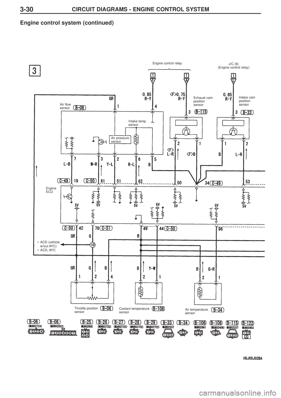
CIRCUIT DIAGRAMS - ENGINE CONTROL SYSTEM3-30
Engine control system (continued)
Engine control relay
Air flow
sensor
Engine
ECU
•ACD (vehicle
w/out AYC)
•ACD, AYC Air pressure
sensor Intake temp.
sensor J/C (6)
(Engine control relay)
Exhaust cam
position
sensorIntake cam
position
sensor
Throttle position
sensorCoolant temperature
sensor Air temperature
sensor
Page 218 of 364
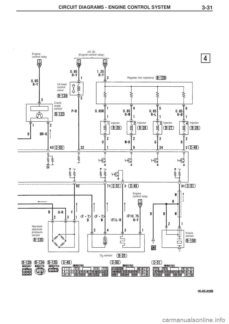
CIRCUIT DIAGRAMS - ENGINE CONTROL SYSTEM3-31
Engine
control relay
Oil feed
control
valve
Crank
angle
sensorRegister (for injectors)
InjectorInjector Injector Injector
Engine
control relay
Knock
sensor
O
2sensor Manifold
absolute
pressure
sensorJ/C (6)
(Engine control relay)
Page 219 of 364
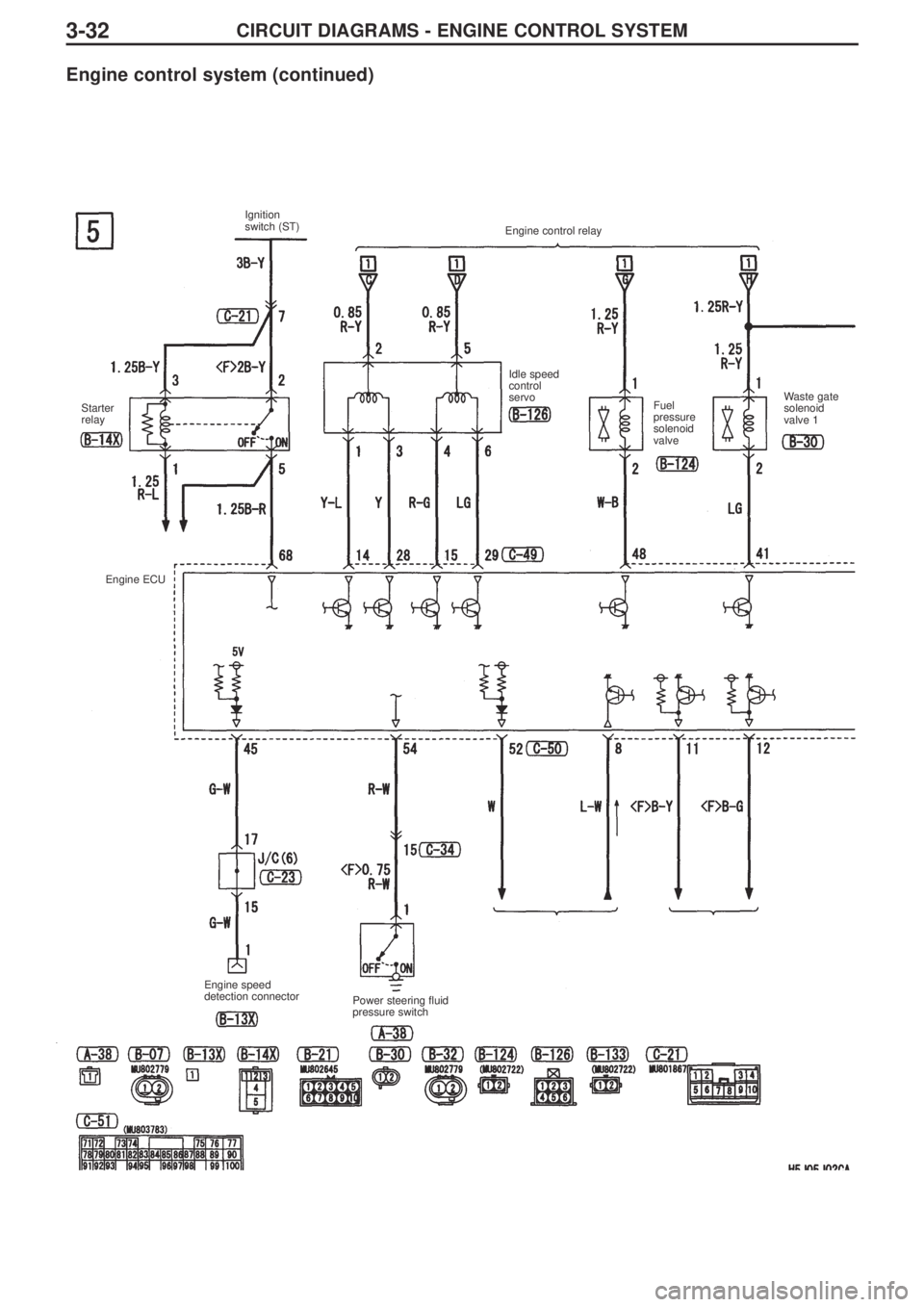
CIRCUIT DIAGRAMS - ENGINE CONTROL SYSTEM3-32
Engine control system (continued)
Ignition
switch (ST)
Starter
relayIdle speed
control
servo
Fuel
pressure
solenoid
valveWaste gate
solenoid
valve 1
Engine ECU
Power steering fluid
pressure switch Engine speed
detection connectorEngine control relay
Page 220 of 364
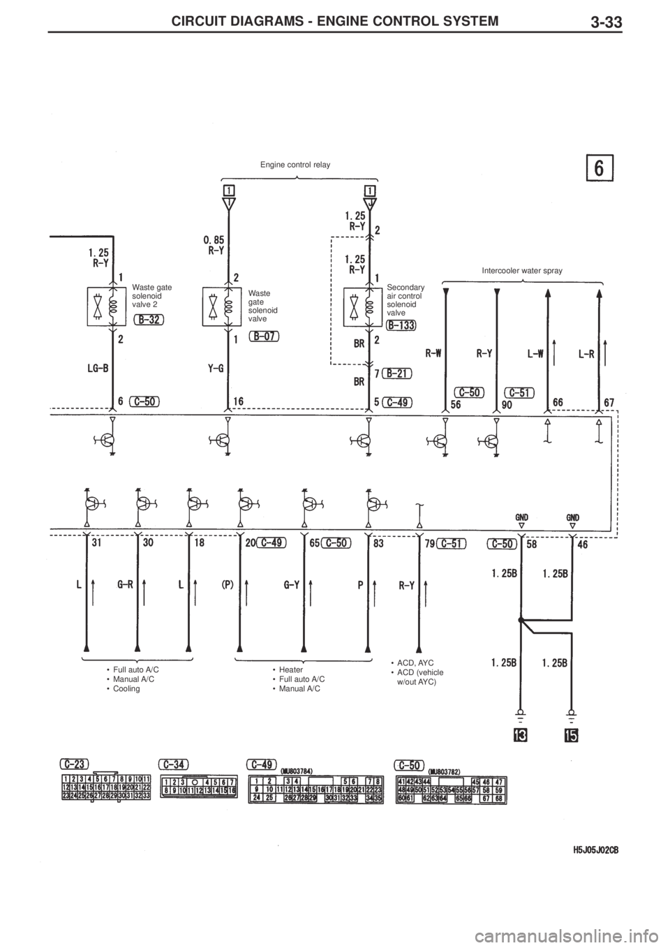
CIRCUIT DIAGRAMS - ENGINE CONTROL SYSTEM3-33
Engine control relay
Waste gate
solenoid
valve 2Waste
gate
solenoid
valveSecondary
air control
solenoid
valve Intercooler water spray
•Full auto A/C
•Manual A/C
•Cooling•Heater
•Full auto A/C
•Manual A/C•ACD, AYC
•ACD (vehicle
w/out AYC)
Page 222 of 364
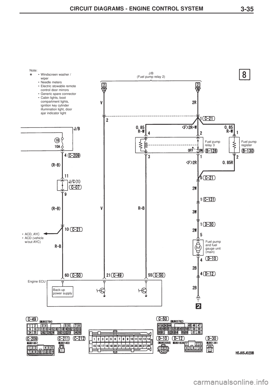
CIRCUIT DIAGRAMS - ENGINE CONTROL SYSTEM3-35
J/B
(Fuel pump relay 2)
Fuel pump
relay 3Fuel pump
register
Fuel pump
and fuel
gauge unit
(main) •ACD, AYC
•ACD (vehicle
w/out AYC)
Engine ECU
Back-up
power supply •Windscreen washer /
wiper
•Needle meters
•Electric stowable remote
control door mirrors
•Generic spare connector
•Cabin lights, boot
compartment lights,
ignition key cylinder
illumination light, door
ajar indicator light Note:*
Page 223 of 364
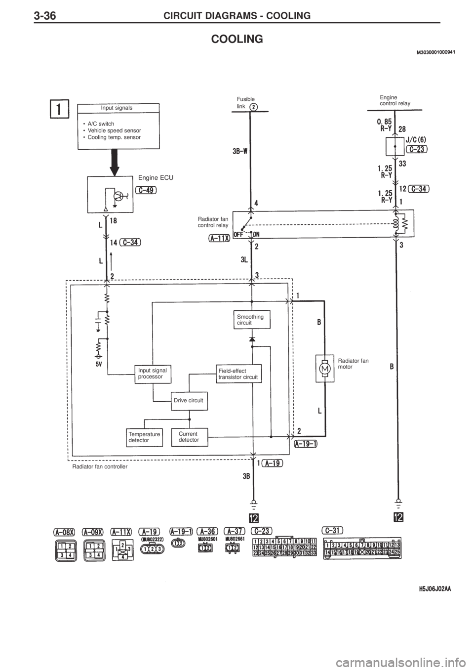
CIRCUIT DIAGRAMS - COOLING3-36
COOLING
Input signals
•A/C switch
•Vehicle speed sensor
•Cooling temp. sensor Fusible
link Engine
control relay
Radiator fan
control relay
Radiator fan
motor Smoothing
circuit
Field-effect
transistor circuit Input signal
processor
Drive circuit
Current
detector Temperature
detector
Radiator fan controller
Engine ECU
