battery MITSUBISHI LANCER EVOLUTION X 2008 Owner's Manual
[x] Cancel search | Manufacturer: MITSUBISHI, Model Year: 2008, Model line: LANCER EVOLUTION X, Model: MITSUBISHI LANCER EVOLUTION X 2008Pages: 241, PDF Size: 8.26 MB
Page 144 of 241
GENERATOR CONTROL
MULTIPORT FUEL SYSTEM (MFI)13A-51
GENERATOR CONTROLM2132025000172
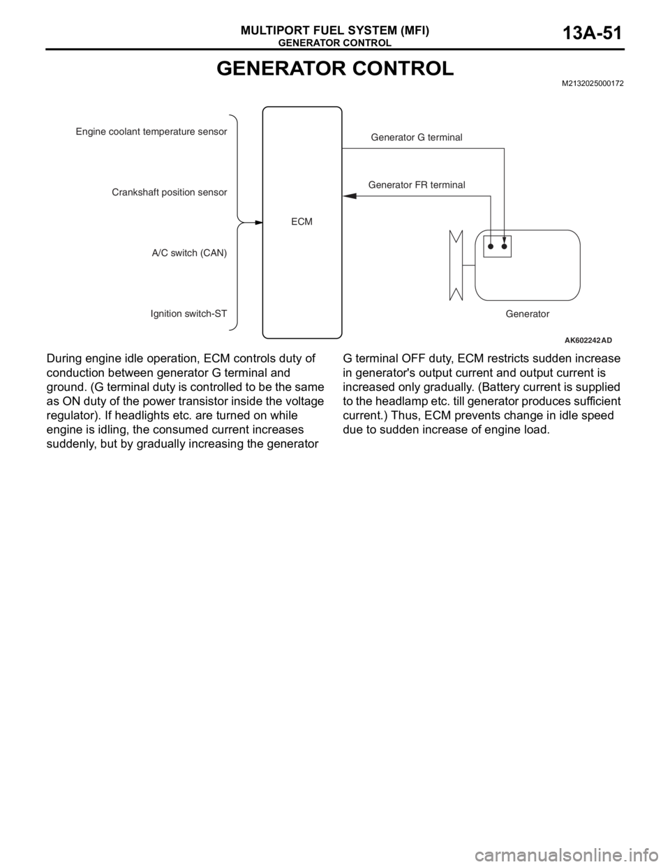
During engine idle operation, ECM controls duty of
conduction between generator G terminal and
ground. (G terminal duty is controlled to be the same
as ON duty of the power transistor inside the voltage
regulator). If headlights etc. are turned on while
engine is idling, the consumed current increases
suddenly, but by gradually increasing the generator G terminal OFF duty, ECM restricts sudden increase
in generator's output current and output current is
increased only gradually. (Battery current is supplied
to the headlamp etc. till generator produces sufficient
current.) Thus, ECM prevents change in idle speed
due to sudden increase of engine load.
AK602242 AD
Engine coolant temperature sensor
Generator G terminal
Generator FR terminal
Generator Crankshaft position sensor
A/C switch (CAN)
Ignition switch-STECM
Page 145 of 241
EVAPORATIVE EMISSION CONTROL SYSTEM INCORRECT PURGE FLOW MONITOR
MULTIPORT FUEL SYSTEM (MFI)13A-52
EVAPORATIVE EMISSION CONTROL SYSTEM INCORRECT
PURGE FLOW MONITOR
M2132027200019
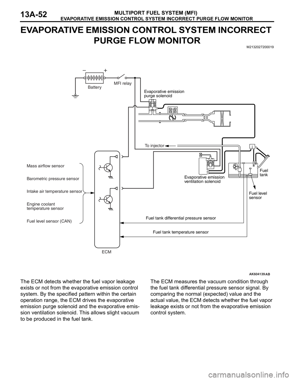
The ECM detects whether the fuel vapor leakage
exists or not from the evaporative emission control
system. By the specified pattern within the certain
operation range, the ECM drives the evaporative
emission purge solenoid and the evaporative emis
-
sion ventilation solenoid. This allows slight vacuum
to be produced in the fuel tank.
The ECM measures the vacuum condition through
the fuel tank differential pressure sensor signal. By
comparing the normal (expected) value and the
actual value, the ECM detects whether the fuel vapor
leakage exists or not from the evaporative emission
control system.
AK604139
Evaporative emission
purge solenoid
Evaporative emission
ventilation solenoid
Fuel tank differential pressure sensor
Fuel tank temperature sensor
AB
BatteryMFI relay
ECM Mass airflow sensor
Barometric pressure sensor
Intake air temperature sensor
Engine coolant
temperature sensor
Fuel level sensor (CAN)Fuel
tank
Fuel level
sensor To injector
Page 180 of 241
FRONT SEAT ASSEMBLY
TSB Revision
INTERIOR52A-19
INSPECTIONM1522005500287
CONTINUITY TEST OF HEATED SEAT SWITCH
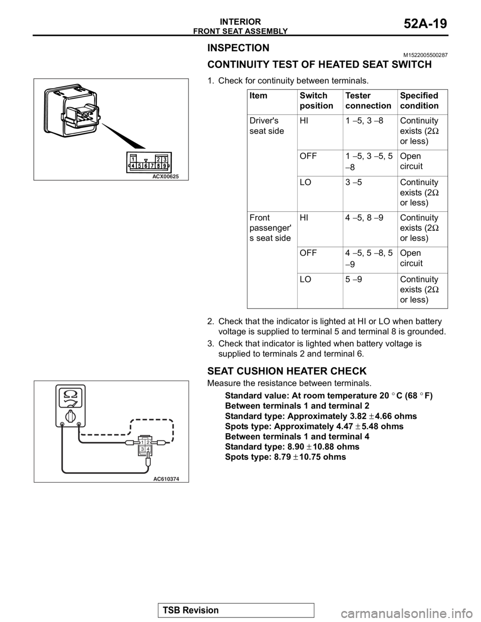
.1. Check for continuity between terminals.
2. Check that the indicator is lighted at HI or LO when battery voltage is supplied to terminal 5 and terminal 8 is grounded.
3. Check that indicator is lighted when battery voltage is
supplied to terminal s 2 and terminal 6.
.
SEAT CUSHION HEATER CHECK
Measure the resistance between terminals.
Standard value: At room temperature 20 °C (68 °F)
Between terminals 1 and terminal 2
Standard type: Approximately 3.82 ± 4.66 ohms
Spots type: Approximately 4.47 ± 5.48 ohms
Between terminals 1 and terminal 4
Standard type: 8.90 ± 10.88 ohms
Spots type: 8.79 ± 10.75 ohms
.
ItemSwitch
positionTester
connectionSpecified
condition
Driver's
seat sideHI1 − 5, 3 − 8Continuity
exists (2
Ω
or less)
OFF1 − 5, 3 − 5, 5
− 8
Open
circuit
LO3 − 5Continuity
exists (2
Ω
or less)
Front
passenger'
s seat sideHI4 − 5, 8 − 9Continuity
exists (2
Ω
or less)
OFF4 − 5, 5 − 8, 5
− 9
Open
circuit
LO5 − 9Continuity
exists (2
Ω
or less)
ACX00625
AC610374
Page 181 of 241
FRONT SEAT ASSEMBLY
TSB Revision
INTERIOR52A-20
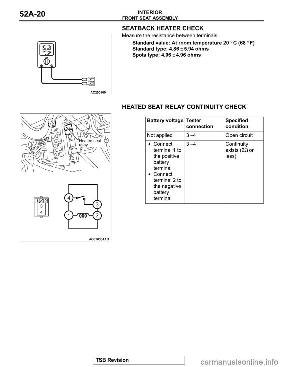
SEATBACK HEATER CHECK
Measure the resistance between terminals.
Standard value: At room temperature 20 °C (68 °F)
Standard type: 4.86 ± 5.94 ohms
Spots type: 4.06 ± 4.96 ohms
HEATED SEAT RELAY CONTINUITY CHECK
12
AC200100
Battery voltageTester
connectionSpecified
condition
Not applied3 − 4Open circuit
•Connect
terminal 1 to
the positive
battery
terminal
•Connect
terminal 2 to
the negative
battery
terminal
3 − 4Continuity
exists (2
Ω or
less)
AC610364
2
3
4
1
AB
Heated seat
relay
Page 189 of 241
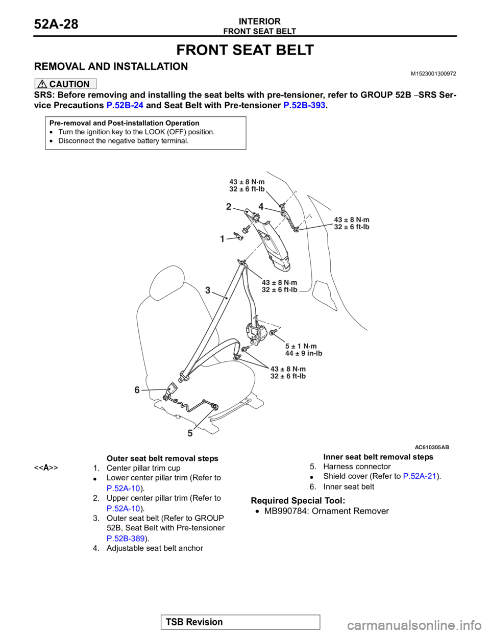
FRONT SEAT BELT
TSB Revision
INTERIOR52A-28
FRONT SEAT BELT
REMOVAL AND INSTALLATIONM1523001300972
CAUTION
SRS: Before removing and installing the seat belts with pre-tensioner, refer to GROUP 52B − SRS Ser-
vice Precautions P.52B-24 and Seat Belt with Pre-tensioner P.52B-393.
Required Special Tool:
•MB990784: Ornament Remover
Pre-removal and Post-installation Operation
•Turn the ignition key to the LOOK (OFF) position.
•Disconnect the negative battery terminal.
AC608130
AC610305
AC608130
1
43 ± 8 N·m
32 ± 6 ft-lb
43 ± 8 N·m
32 ± 6 ft-lb
AB
3
24
5
43 ± 8 N·m
32 ± 6 ft-lb
5 ± 1 N·m
44 ± 9 in-lb
43 ± 8 N·m
32 ± 6 ft-lb
6
Outer seat belt removal steps
<>1.Center pillar trim cup
•Lower center pillar trim (Refer to
P.52A-10).
2.Upper center pillar trim (Refer to
P.52A-10).
3.Outer seat belt (Refer to GROUP
52B, Seat Belt with Pre-tensioner
P.52B-389).
4.Adjustable seat belt anchor
Inner seat belt removal steps
5.Harness connector
•Shield cover (Refer to P.52A-21).
6.Inner seat belt
Page 220 of 241

CONSTRUCTION DESCRIPTION
FOUR-WHEEL ANTI-LOCK BRAKE SYSTEM (4ABS)35B-11
NOTE: .
•*1 This diagnostic trouble code is not set within
the vehicle speed of 20 km/h (12 mph) or less.
•*2 Turns ON when two or more wheels are faulty.
•*3 Stays ON until the vehicle speed reaches 10
km/h (6 mph) when the ignition switch is turned to
ON next time.
DIAGNOSTIC FUNCTION
ABS-ECU has the following functions for easier sys-
tem checks. The following items can be diagnosed
using scan tool.
•Diagnostic trouble code set
•Service data output
•Actuator test.
DIAGNOSTIC TROUBLE CODE SET
There are 43 diagnosis items. Since all the diagnos-
tic results are recorded in volatile memory
(EEPROM*), they are stored in the memory even
though the battery terminals are disconnected.
NOTE: .
•*EEPROM (Electrical Erasable & Programmable
ROM): Special type of memory that can be pro
-
grammed or erased electrically
•For each diagnosis item, refer to Service Manual.
.
SERVICE DATA OUTPUT
Using scan tool, the input data sent from the sensors
and switches can be read.
NOTE: For service data items, refer to Service Man-
ual.
.
C2116Abnormality in pump motor
power supply voltageExecutedProhibitedExtinguishedIlluminated*3
C1000Abnormality in stop light switch
circuitExecutedExecutedExtinguishedExtinguished
C2200Abnormality in ABS-ECUProhibitedProhibitedIlluminatesIlluminates
C2100Battery
voltage
problem (low
voltage)9.7 ± 0.3 V or
less
*1
ExecutedProhibitedExtinguishedIlluminates
8.0 ± 0.5 V or
less
*1
ProhibitedProhibitedIlluminatesIlluminates
C2101Battery
voltage
problem (high
voltage)18.0 ± 1.0 V or
moreProhibitedProhibitedIlluminatesIlluminates
C1395Brake fluid filling not completedExecutedExecutedExtinguishedFlashes (1 Hz)
C2203VIN not writtenExecutedExecutedExtinguishedIlluminates
C1608Implausible diagnosis dataExecutedExecutedExtinguishedExtinguished
U0001Bus offExecutedExecutedExtinguishedExtinguished
U0100Engine time-out errorExecutedExecutedExtinguishedExtinguished
U0141ETACS time-out errorExecutedExecutedExtinguishedExtinguished
U1415Variant coding not implementedExecutedProhibitedExtinguishedIlluminates
U1417Invalid variant coding value
(including wrong assembly)ExecutedProhibitedExtinguishedIlluminates
DTC
No.Item Countermeasures for failure
EBD control ABS control Brake
warning lightABS warning
light