battery MITSUBISHI LANCER EVOLUTION X 2008 User Guide
[x] Cancel search | Manufacturer: MITSUBISHI, Model Year: 2008, Model line: LANCER EVOLUTION X, Model: MITSUBISHI LANCER EVOLUTION X 2008Pages: 241, PDF Size: 8.26 MB
Page 125 of 241
FUEL INJECTION CONTROL
MULTIPORT FUEL SYSTEM (MFI)13A-32
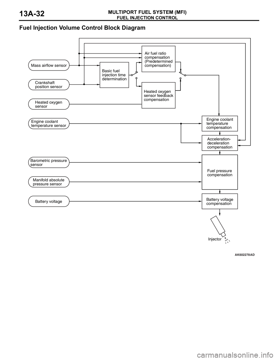
Fuel Injection Volume Control Block Diagram
.
AK602278AD
Mass airflow sensor
Crankshaft
position sensor
Heated oxygen
sensor
Engine coolant
temperature
compensation Engine coolant
temperature sensor
Manifold absolute
pressure sensorFuel pressure
compensation Barometric pressure
sensor
Battery voltage
compensation Battery voltageBasic fuel
injection time
determinationAir fuel ratio
compensation
(Predetermined
compensation)
Heated oxygen
sensor feedback
compensation
Injector Acceleration-
deceleration
compensation
Page 127 of 241
![MITSUBISHI LANCER EVOLUTION X 2008 User Guide FUEL INJECTION CONTROL
MULTIPORT FUEL SYSTEM (MFI)13A-34
[Injector drive time compensation]
After calculating the injector basic drive time, the ECM makes
the following compensations to control the o MITSUBISHI LANCER EVOLUTION X 2008 User Guide FUEL INJECTION CONTROL
MULTIPORT FUEL SYSTEM (MFI)13A-34
[Injector drive time compensation]
After calculating the injector basic drive time, the ECM makes
the following compensations to control the o](/img/19/57326/w960_57326-126.png)
FUEL INJECTION CONTROL
MULTIPORT FUEL SYSTEM (MFI)13A-34
[Injector drive time compensation]
After calculating the injector basic drive time, the ECM makes
the following compensations to control the optimum fuel injec
-
tion volume according to driving conditions.
List of main compensations for fuel injection control
.
[Fuel limit control during deceleration]
ECM limits fuel when decelerating downhill to prevent exces-
sive rise of catalytic converter temperature and to improve fuel
efficiency.
.
[Fuel-cut control when over-run]
When engine speed exceeds a prescribed limit (6,600 r/min),
ECM cuts fuel supply to prevent overrunning and thus protect
the engine. Also, if engine speed exceeds 4,000 r/min for 15
seconds while vehicle is stationary (no load), it cuts fuel supply
and controls the throttle valve opening angle to protect the
engine.
CompensationsContent
Heated oxygen sensor feedback compensationThe heated oxygen sensor signal is used for
making the compensation to get air-fuel ratio with
best cleaning efficiency of the 3-way catalytic
converter. This compensation might not be made
sometimes in order to improve drivability,
depending on driving conditions. (Air-fuel ratio
compensation is made.)
Air-fuel ratio compensationUnder driving conditions where heated oxygen
sensor feedback compensation is not performed,
compensation is made based on pre-set map
values that vary according to engine speed and
intake air volume.
Engine coolant temperature compensationCompensation is made according to the engine
coolant temperature. The lower the engine coolant
temperature, the greater the fuel injection volume.
Acceleration/ Deceleration compensationCompensation is made according to change in
intake air volume. During acceleration, fuel injection
volume is increased. Also, during deceleration, fuel
injection volume is decreased.
Fuel injection compensationCompensation is made according to the pressure
difference between atmospheric pressure and
manifold absolute pressure. The greater the
difference in pressure, the shorter the injector drive
time.
Battery voltage compensationCompensation is made depending on battery
voltage. The lower the battery voltage, the greater
the injector drive signal time.
Learning value for fuel compensationCompensation amount is learned to compensate
feedback of heated oxygen sensor. This allows
system to compensate in accordance with engine
characteristics.
Page 128 of 241
IGNITION TIMING AND CONTROL FOR CURRENT CARRYING TIME
MULTIPORT FUEL SYSTEM (MFI)13A-35
IGNITION TIMING AND CONTROL FOR CURRENT
CARRYING TIME
M2132027100089
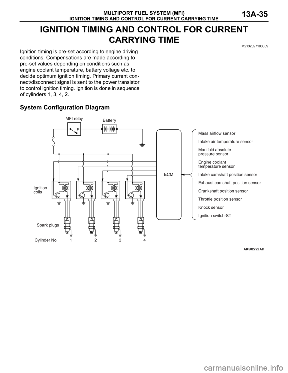
Ignition timing is pre-set according to engine driving
conditions. Compensations are made according to
pre-set values depending on conditions such as
engine coolant temperature, battery voltage etc. to
decide optimum ignition timing. Primary current con
-
nect/disconnect signal is sent to the power transistor
to control ignition timing. Ignition is done in sequence
of cylinders 1, 3, 4, 2.
System Configuration Diagram
AK502722AD
ECM MFI relay
Spark plugs Ignition
coils
Cylinder No. 1 2 3 4Battery
Mass airflow sensor
Intake air temperature sensor
Manifold absolute
pressure sensor
Engine coolant
temperature sensor
Intake camshaft position sensor
Exhaust camshaft position sensor
Crankshaft position sensor
Knock sensor
Ignition switch-ST Throttle position sensor
Page 130 of 241
![MITSUBISHI LANCER EVOLUTION X 2008 User Guide IGNITION TIMING AND CONTROL FOR CURRENT CARRYING TIME
MULTIPORT FUEL SYSTEM (MFI)13A-37
2. Spark-advance control and current carrying
time control
.
[During start]
ECM initiates ignition at fixed ign MITSUBISHI LANCER EVOLUTION X 2008 User Guide IGNITION TIMING AND CONTROL FOR CURRENT CARRYING TIME
MULTIPORT FUEL SYSTEM (MFI)13A-37
2. Spark-advance control and current carrying
time control
.
[During start]
ECM initiates ignition at fixed ign](/img/19/57326/w960_57326-129.png)
IGNITION TIMING AND CONTROL FOR CURRENT CARRYING TIME
MULTIPORT FUEL SYSTEM (MFI)13A-37
2. Spark-advance control and current carrying
time control
.
[During start]
ECM initiates ignition at fixed ignition timing (5° BTDC) syn-
chronized with the crankshaft position sensor signal.
.
[During normal operation]
After determining the basic spark-advance based on the intake
air volume and engine speed, ECM makes compensations
based on input from various sensors to control the optimum
spark-advance and current carrying time.
List of main compensations for spark-advance control and current carrying time control
.
[Control for checking ignition timing]
During basic ignition timing set mode for M.U.T.-III actuator test
function, sparking is done with fixed ignition timing (5
° BTDC)
synchronized with crankshaft position sensor signal.
CompensationsContent
Intake air temperature compensationCompensation is made according to intake air
temperature. The higher the intake air temperature
the greater the delay in ignition timing.
Engine coolant temperature compensationCompensation is made according to engine coolant
temperature. The lower the engine coolant
temperature the greater the advance in ignition
timing.
Knocking compensationCompensation is made according to generation of
knocking. The greater the knocking the greater the
delay in ignition timing.
Stable idle compensationCompensation is made according to change in idle
speed. In case engine speed becomes lower than
target speed, ignition timing is advanced.
Delay compensation when changing shiftDuring change of shift, sparking is delayed
compared to normal ignition timing to reduce
engine output torque and absorb the shock of the
shift change.
Battery voltage compensationCompensation is made depending on battery
voltage. The lower the battery voltage the greater
the current carrying time and when battery voltage
is high current carrying time is shortened.
Page 138 of 241
MULTIPORT FUEL INJECTION (MFI) RELAY CONTROL
MULTIPORT FUEL SYSTEM (MFI)13A-45
MULTIPORT FUEL INJECTION (MFI) RELAY CONTROLM2132006000173
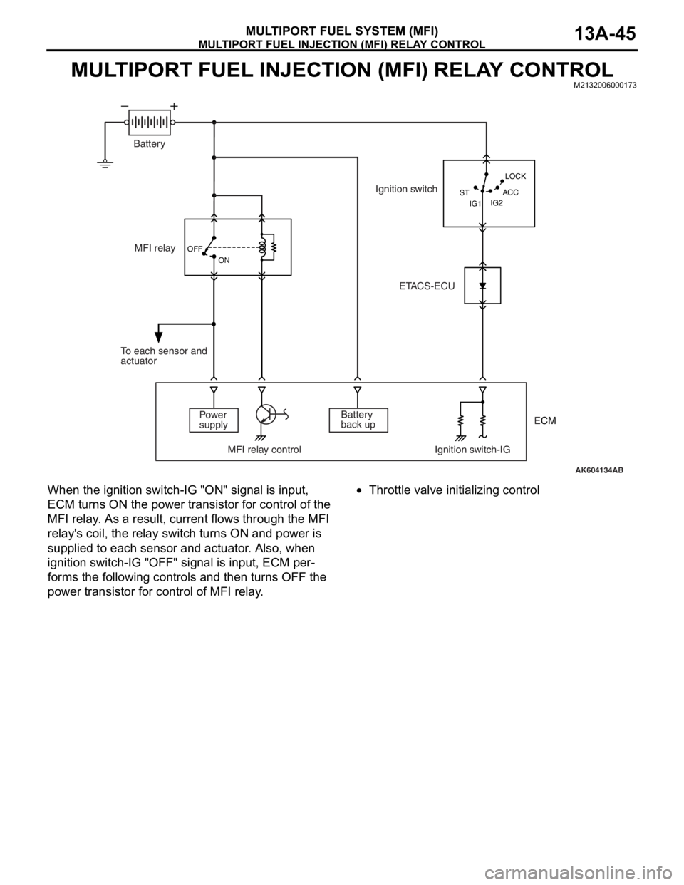
When the ignition switch-IG "ON" signal is input,
ECM turns ON the power transistor for control of the
MFI relay. As a result, current flows through the MFI
relay's coil, the relay switch turns ON and power is
supplied to each sensor and actuator. Also, when
ignition switch-IG "OFF" signal is input, ECM per
-
forms the following controls and then turns OFF the
power transistor for control of MFI relay.
•Throttle valve initializing control
AK604134AB OFF
ON
IG2 STLOCK
ACC
IG1
MFI relay
Power
supply
MFI relay control Ignition switch-IGBattery
back up To each sensor and
actuatorIgnition switch
ETACS-ECU Battery
ECM
Page 139 of 241
FUEL PUMP RELAY CONTROL
MULTIPORT FUEL SYSTEM (MFI)13A-46
FUEL PUMP RELAY CONTROLM2132006500208
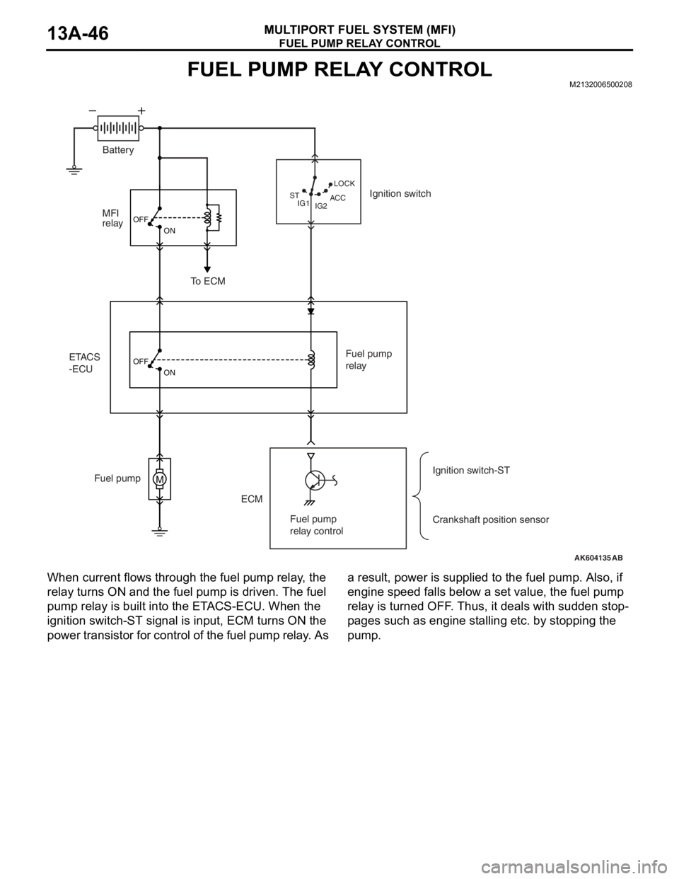
When current flows through the fuel pump relay, the
relay turns ON and the fuel pump is driven. The fuel
pump relay is built into the ETACS-ECU. When the
ignition switch-ST signal is input, ECM turns ON the
power transistor for control of the fuel pump relay. As a result, power is supplied to the fuel pump. Also, if
engine speed falls below a set value, the fuel pump
relay is turned OFF. Thus, it deals with sudden stop
-
pages such as engine stalling etc. by stopping the
pump.
AK604135
M
OFF
ON
OFF
ON
AB IG2 STLOCK
ACC
IG1
ETACS
-ECUMFI
relay
ECM Fuel pumpFuel pump
relay
Crankshaft position sensor Ignition switch
To ECM
Ignition switch-ST Battery
Fuel pump
relay control
Page 140 of 241
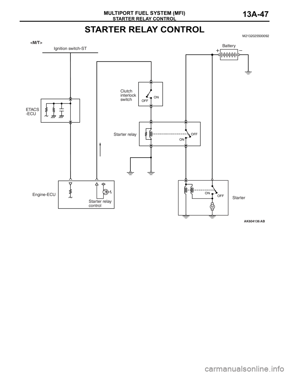
STARTER RELAY CONTROL
MULTIPORT FUEL SYSTEM (MFI)13A-47
STARTER RELAY CONTROLM2132025500092
AK604136
M
AB OFF ON OFF
ON
Engine-ECU
Starter relay
controlClutch
interlock
switch
ETACS
-ECUIgnition switch-STBattery
Starter relay
Starter
OFFON
Page 141 of 241
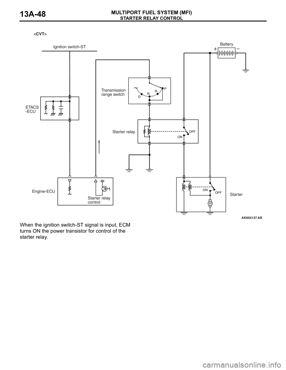
STARTER RELAY CONTROL
MULTIPORT FUEL SYSTEM (MFI)13A-48
When the ignition switch-ST signal is input, ECM
turns ON the power transistor for control of the
starter relay.
AK604137
M
AB P
DNR
OFF ON OFF
ON
Engine-ECU
Starter relay
controlTransmission
range switch Ignition switch-STBattery
Starter relay
Starter ETACS
-ECU
Page 142 of 241
HEATED OXYGEN SENSOR HEATER CONTROL
MULTIPORT FUEL SYSTEM (MFI)13A-49
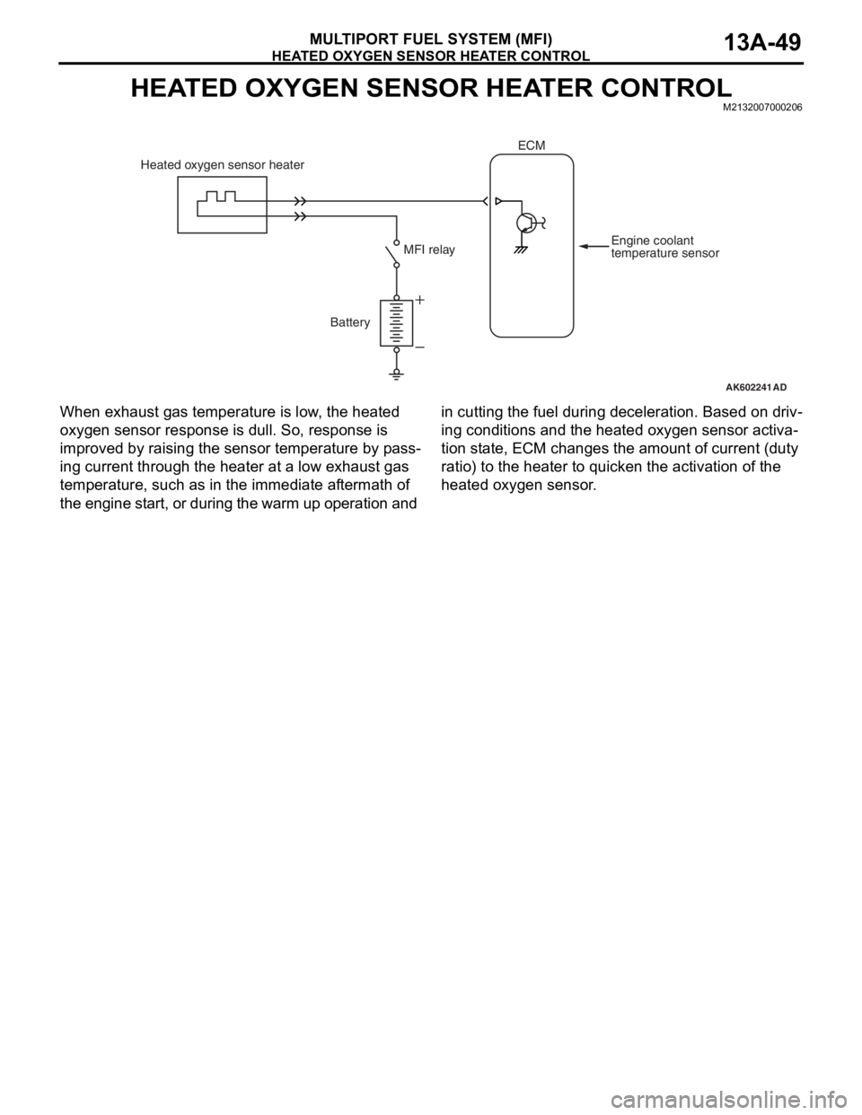
HEATED OXYGEN SENSOR HEATER CONTROLM2132007000206
When exhaust gas temperature is low, the heated
oxygen sensor response is dull. So, response is
improved by raising the sensor temperature by pass
-
ing current through the heater at a low exhaust gas
temperature, such as in the immediate aftermath of
the engine start, or during the warm up operation and in cutting the fuel during deceleration. Based on driv
-
ing conditions and the heated oxygen sensor activa-
tion state, ECM changes the amount of current (duty
ratio) to the heater to quicken the activation of the
heated oxygen sensor.
AK602241AD
Battery Heated oxygen sensor heater
Engine coolant
temperature sensor MFI relay
ECM
Page 143 of 241
A/C COMPRESSOR RELAY CONTROL
MULTIPORT FUEL SYSTEM (MFI)13A-50
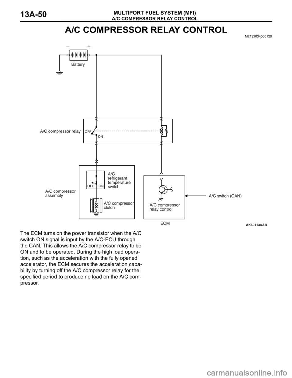
A/C COMPRESSOR RELAY CONTROLM2132034500120
The ECM turns on the power transistor when the A/C
switch ON signal is input by the A/C-ECU through
the CAN. This allows the A/C compressor relay to be
ON and to be operated. During the high load opera
-
tion, such as the acceleration with the fully opened
accelerator, the ECM secures the acceleration capa
-
bility by turning off the A/C compressor relay for the
specified period to produce no load on the A/C com
-
pressor.
AK604138
OFF
ON
AB
Battery
A/C compressor relay
A/C compressor
assembly
A/C compressor
relay control A/C compressor
clutch
A/C
refrigerant
temperature
switch
OFF ON
A/C switch (CAN)
ECM