relay MITSUBISHI LANCER EVOLUTION X 2008 Owner's Guide
[x] Cancel search | Manufacturer: MITSUBISHI, Model Year: 2008, Model line: LANCER EVOLUTION X, Model: MITSUBISHI LANCER EVOLUTION X 2008Pages: 241, PDF Size: 8.26 MB
Page 181 of 241

FRONT SEAT ASSEMBLY
TSB Revision
INTERIOR52A-20
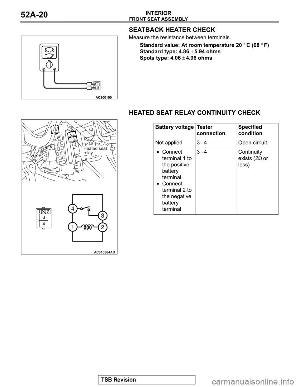
SEATBACK HEATER CHECK
Measure the resistance between terminals.
Standard value: At room temperature 20 °C (68 °F)
Standard type: 4.86 ± 5.94 ohms
Spots type: 4.06 ± 4.96 ohms
HEATED SEAT RELAY CONTINUITY CHECK
12
AC200100
Battery voltageTester
connectionSpecified
condition
Not applied3 − 4Open circuit
•Connect
terminal 1 to
the positive
battery
terminal
•Connect
terminal 2 to
the negative
battery
terminal
3 − 4Continuity
exists (2
Ω or
less)
AC610364
2
3
4
1
AB
Heated seat
relay
Page 214 of 241

GENERAL INFORMATION
FOUR-WHEEL ANTI-LOCK BRAKE SYSTEM (4ABS)35B-5
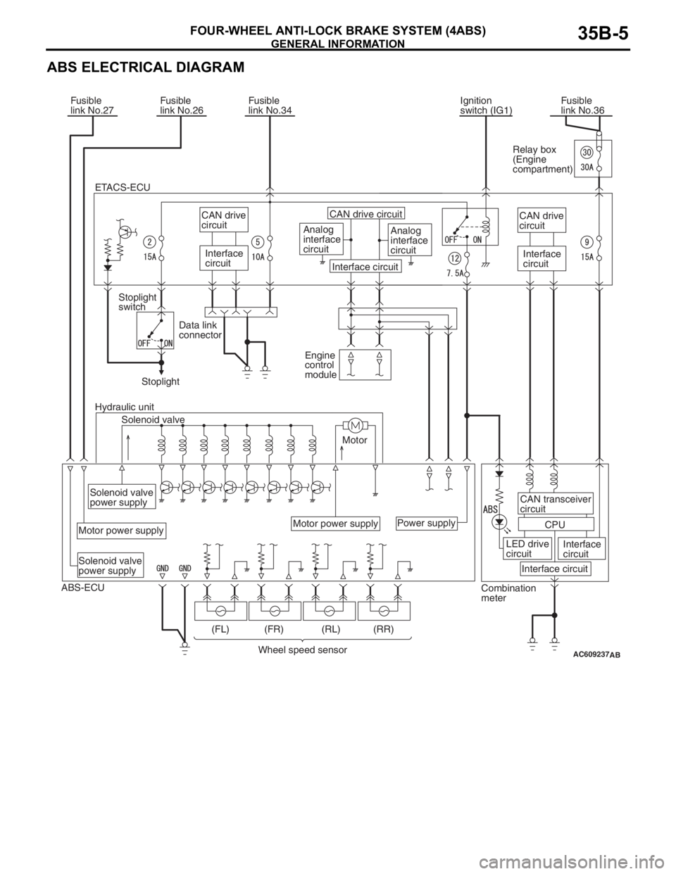
ABS ELECTRICAL DIAGRAM
AC609237
Ignition
switch (IG1) Fusible
link No.34Fusible
link No.36 Fusible
link No.27Fusible
link No.26
Analog
interface
circuitAnalog
interface
circuit CAN drive circuit
Interface circuit
Solenoid valve Stoplight
switch
Motor Hydraulic unitStoplightEngine
control
module Data link
connector
Solenoid valve
power supplySolenoid valve
power supply
Motor power supplyMotor power supplyPower supplyCAN drive
circuit
Interface
circuit
CAN transceiver
circuit
CPU
LED drive
circuitInterface
circuit
Interface circuit
Wheel speed sensor (FL) (FR) (RL) (RR)Relay box
(Engine
compartment)
Combination
meter
AB
ABS-ECUCAN drive
circuit
Interface
circuit ETACS-ECU
Page 218 of 241

CONSTRUCTION DESCRIPTION
FOUR-WHEEL ANTI-LOCK BRAKE SYSTEM (4ABS)35B-9
STARTUP CHECK
.When the startup vehicle speed reaches approxi-
mately 10 km/h (6 mph), ABS-ECU performs the fol-
lowing checks.
1. Motor, solenoid valve check (Initial startup* only)
Turns ON the motor relay in ECU, and checks the
pump motor operation. At the same time,
ABS-ECU sequentially energizes each solenoid
valve in a very short period and checks the valve
operation.
NOTE: *: Initial startup indicates a first startup
after the system has started.
2. Wheel speed sensor check
ABS-ECU checks for any wheels that have not
received wheel speed sensor signal from the
startup.
CONSTANT CHECK
.ABS-ECU constantly checks the following items.
1. ABS-ECU
Performs self-diagnosis in ECU.
2. ECU power supply
Checks if ECU power supply voltage stays within
the operational range.
3. Wheel speed sensor
(1) Monitors the output voltage of the sensor
signal wiring harness and checks for abnormal
output voltage (open/short circuit).
(2) Checks for any wheels that do not send pulse
signal while the vehicle is in motion.
(3) Checks if wheel speed which is abnormally
higher or lower than the vehicle speed is input.
4. Pump motor, solenoid valve
Checks that the ABS-ECU output signal and the
operating conditions of the pump motor and
solenoid valve agree with each other.
CAN COMMUNICATION
ABS-ECU outputs the ABS warning light and the
EBD warning light
* illumination request signals to the
combination meter through CAN communication.
NOTE: *: The brake warning light is used as EBD
control warning light.
FAIL-SAFE FUNCTION
If any malfunction is detected by the self-diagnostic
function, ABS-ECU illuminates the ABS warning light
and brake warning light
*, and it disables ABS and
EBD control.
NOTE: *: The brake warning light is used as EBD
control warning light.
DTC
No.ItemCountermeasures for failure
EBD controlABS controlBrake
warning lightABS warning
light
C100AAbnormality in FL wheel speed
sensor circuitExecuted
(Prohibited
when two or
more wheels
are faulty.)ProhibitedExtinguished*2Illuminated*3
C1015Abnormality in FR wheel speed
sensor circuit
C1020Abnormality in RL wheel speed
sensor circuit
C102BAbnormality in RR wheel speed
sensor circuit
C1011Abnormality in FL wheel speed
sensor signalExecuted
(Prohibited
when two or
more wheels
are faulty.)ProhibitedExtinguished*2Illuminated*3
C101CAbnormality in FR wheel speed
sensor signal
C1027Abnormality in RL wheel speed
sensor signal
C1032Abnormality in RR wheel speed
sensor signal