relay MITSUBISHI LANCER EVOLUTION X 2008 User Guide
[x] Cancel search | Manufacturer: MITSUBISHI, Model Year: 2008, Model line: LANCER EVOLUTION X, Model: MITSUBISHI LANCER EVOLUTION X 2008Pages: 241, PDF Size: 8.26 MB
Page 95 of 241
13A-1
GROUP 13A
MULTIPORT FUEL
SYSTEM (MFI)
CONTENTS
GENERAL DESCRIPTION. . . . . . . . .13A-2
CONTROL UNIT. . . . . . . . . . . . . . . . .13A-6
SENSOR. . . . . . . . . . . . . . . . . . . . . . .13A-8
ACTUATOR . . . . . . . . . . . . . . . . . . . .13A-23
FUEL INJECTION CONTROL . . . . . .13A-29
IGNITION TIMING AND CONTROL FOR
CURRENT CARRYING TIME . . . . . .13A-35
THROTTLE VALVE OPENING ANGLE
CONTROL AND IDLE SPEED
CONTROL . . . . . . . . . . . . . . . . . . . . .13A-38
MIVEC (Mitsubishi Innovative Valve
Timing Electronic Control System) .13A-40
MULTIPORT FUEL INJECTION (MFI)
RELAY CONTROL . . . . . . . . . . . . . . .13A-45
FUEL PUMP RELAY CONTROL . . . .13A-46
STARTER RELAY CONTROL . . . . . .13A-47
HEATED OXYGEN SENSOR HEATER
CONTROL . . . . . . . . . . . . . . . . . . . . . .13A-49
A/C COMPRESSOR RELAY
CONTROL . . . . . . . . . . . . . . . . . . . . . .13A-50
GENERATOR CONTROL . . . . . . . . . .13A-51
EVAPORATIVE EMISSION CONTROL
SYSTEM INCORRECT PURGE FLOW
MONITOR . . . . . . . . . . . . . . . . . . . . . .13A-52
EXHAUST GAS RECIRCULATION
CONTROL . . . . . . . . . . . . . . . . . . . . . .13A-53
CONTROLLER AREA NETWORK
(CAN) . . . . . . . . . . . . . . . . . . . . . . . . .13A-53
EVAPORATIVE EMISSION PURGE
CONTROL . . . . . . . . . . . . . . . . . . . . . .13A-53
HC TRAP CATALYTIC CONVERTER
DETERIORATION MONITOR . . . . . . .13A-53
ON-BOARD DIAGNOSTICS . . . . . . . .13A-53
Page 97 of 241
GENERAL DESCRIPTION
MULTIPORT FUEL SYSTEM (MFI)13A-3
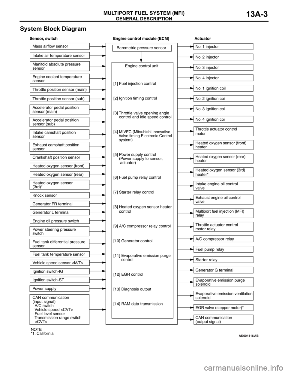
System Block Diagram
AK604116
Mass airflow sensor
Intake air temperature sensor
Intake camshaft position
sensor
Exhaust camshaft position
sensor
Crankshaft position sensor Throttle position sensor (main)
Throttle position sensor (sub)
Accelerator pedal position
sensor (sub) Accelerator pedal position
sensor (main) Engine coolant temperature
sensor Manifold absolute pressure
sensor
Heated oxygen sensor (front)
Heated oxygen sensor (rear)
Power steering pressure
switch Engine oil pressure switch Generator L terminal
Ignition switch-ST
Power supply Ignition switch-IG
CAN communication
(input signal)
· A/C switch
· Vehicle speed
· Fuel level sensor
· Transmission range switch
sensor Heated oxygen sensor
(3rd)*
Knock sensor
Generator FR terminal
Fuel tank temperature sensor
Vehicle speed sensor
[1] Fuel injection control
[2] Ignition timing control
[3] Throttle valve opening angle
control and idle speed control
[4]
MIVEC (Mitsubishi Innovative
Valve timing Electronic Control
system)
[5] Power supply control
(Power supply to sensor,
actuator)
[6] Fuel pump relay control
[7] Starter relay control
[8] Heated oxygen sensor heater
control
[9] A/C compressor relay control
[10] Generator control
[11] Evaporative emission purge
control
[12] EGR control
[13] Diagnosis output
[14] RAM data transmission
CAN communication
(output signal) Intake engine oil control
valve
A/C compressor relay No. 2 injector
No. 3 injector
No. 4 injector
Heated oxygen sensor (front)
heater
Heated oxygen sensor (rear)
heater Throttle actuator control
motor
Throttle actuator control
motor relay No. 1 injector
No. 1 ignition coil
No. 2 ignition coi
No. 3 ignition coi
No. 4 ignition coi
Fuel pump relay
Generator G terminal Heated oxygen sensor (3rd)
heater*
Multiport fuel injection (MFI)
relay Exhaust engine oil control
valve
Evaporative emission ventilation
solenoid Evaporative emission purge
solenoid
EGR valve (stepper motor)*
Starter relay
AB
Sensor, switch Engine control module (ECM) Actuator
NOTE
*1: California
Page 98 of 241
GENERAL DESCRIPTION
MULTIPORT FUEL SYSTEM (MFI)13A-4
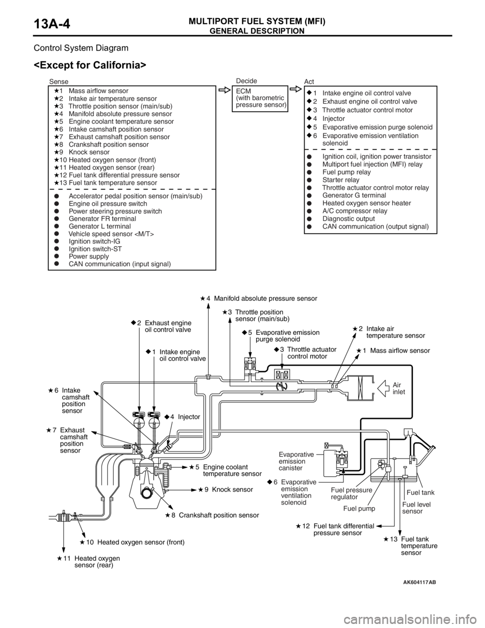
Control System Diagram
AK604117
Fuel level
sensorFuel tank Air
inlet
2 Exhaust engine
oil control valve
1 Intake engine
oil control valve4 Manifold absolute pressure sensor
2 Intake air
temperature sensor
1 Mass airflow sensor
6 Intake
camshaft
position
sensor
7 Exhaust
camshaft
position
sensor
3 Throttle position
sensor (main/sub)
5 Evaporative emission
purge solenoid
3 Throttle actuator
control motor
12 Fuel tank differential
pressure sensor
13 Fuel tank
temperature
sensor10 Heated oxygen sensor (front)
11 Heated oxygen
sensor (rear)
8 Crankshaft position sensor5 Engine coolant
temperature sensor
9 Knock sensor
4 Injector
Fuel pump Fuel pressure
regulator Evaporative
emission
canister
6 Evaporative
emission
ventilation
solenoid
1 Mass airflow sensor
2 Intake air temperature sensor
3 Throttle position sensor (main/sub)
4 Manifold absolute pressure sensor
5 Engine coolant temperature sensor
6 Intake camshaft position sensor
7 Exhaust camshaft position sensor
8 Crankshaft position sensor
9 Knock sensor
10 Heated oxygen sensor (front)
11 Heated oxygen sensor (rear)
12 Fuel tank differential pressure sensor
13 Fuel tank temperature sensor
Ignition switch-IG
Ignition switch-ST
Power supply
CAN communication (input signal)1 Intake engine oil control valve
2 Exhaust engine oil control valve
3 Throttle actuator control motor
4 Injector
5 Evaporative emission purge solenoid
6 Evaporative emission ventilation
solenoid
Ignition coil, ignition power transistor
Multiport fuel injection (MFI) relay
Fuel pump relay
Starter relay
Throttle actuator control motor relay
Generator G terminal
Heated oxygen sensor heater
A/C compressor relay
Diagnostic output
CAN communication (output signal) SenseAct
Engine oil pressure switch
Power steering pressure switch
Generator FR terminal
Generator L terminal
Vehicle speed sensor
Decide
ECM
(with barometric
pressure sensor)
AB
Page 99 of 241
GENERAL DESCRIPTION
MULTIPORT FUEL SYSTEM (MFI)13A-5
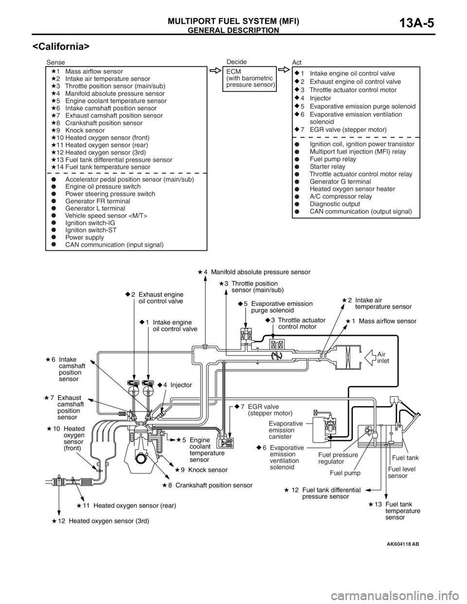
AK604118
Fuel tank
Fuel level
sensor Air
inlet
2 Exhaust engine
oil control valve
1 Intake engine
oil control valve4 Manifold absolute pressure sensor
2 Intake air
temperature sensor
1 Mass airflow sensor
6 Intake
camshaft
position
sensor
7 Exhaust
camshaft
position
sensor
3 Throttle position
sensor (main/sub)
5 Evaporative emission
purge solenoid
3 Throttle actuator
control motor
12 Fuel tank differential
pressure sensor
13 Fuel tank
temperature
sensor11 Heated oxygen sensor (rear)
10 Heated
oxygen
sensor
(front)
12 Heated oxygen sensor (3rd)
8 Crankshaft position sensor5 Engine
coolant
temperature
sensor
9 Knock sensor
4 Injector
Fuel pump Fuel pressure
regulator Evaporative
emission
canister
6 Evaporative
emission
ventilation
solenoid
7 EGR valve
(stepper motor)
1 Mass airflow sensor
2 Intake air temperature sensor
3 Throttle position sensor (main/sub)
4 Manifold absolute pressure sensor
5 Engine coolant temperature sensor
6 Intake camshaft position sensor
7 Exhaust camshaft position sensor
8 Crankshaft position sensor
9 Knock sensor
10 Heated oxygen sensor (front)
11 Heated oxygen sensor (rear)
12 Heated oxygen sensor (3rd)
13 Fuel tank differential pressure sensor
14 Fuel tank temperature sensor
Ignition switch-IG
Ignition switch-ST
Power supply
CAN communication (input signal)1 Intake engine oil control valve
2 Exhaust engine oil control valve
3 Throttle actuator control motor
4 Injector
5 Evaporative emission purge solenoid
6 Evaporative emission ventilation
solenoid
7 EGR valve (stepper motor)
Ignition coil, ignition power transistor
Multiport fuel injection (MFI) relay
Fuel pump relay
Starter relay
Throttle actuator control motor relay
Generator G terminal
Heated oxygen sensor heater
A/C compressor relay
Diagnostic output
CAN communication (output signal) SenseAct
Engine oil pressure switch
Power steering pressure switch
Generator FR terminal
Generator L terminal
Vehicle speed sensor
Decide
ECM
(with barometric
pressure sensor)
AB
Page 101 of 241
SENSOR
MULTIPORT FUEL SYSTEM (MFI)13A-8
SENSORM2132001000565.
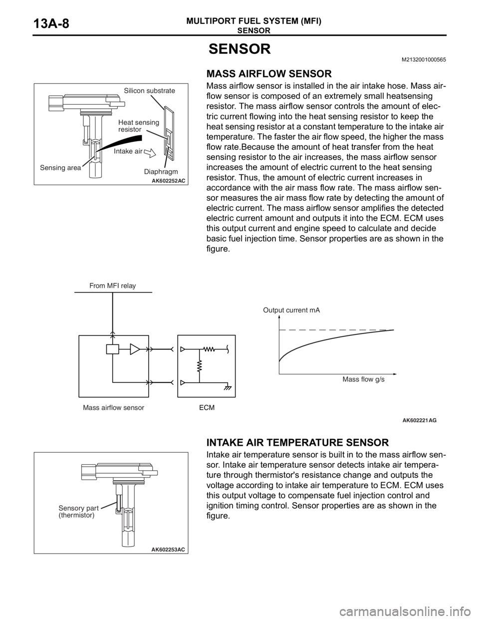
MASS AIRFLOW SENSOR
Mass airflow sensor is installed in the air intake hose. Mass air-
flow sensor is composed of an extremely small heatsensing
resistor. The mass airflow sensor controls the amount of elec
-
tric current flowing into the heat sensing resistor to keep the
heat sensing resistor at a constant temperature to the intake air
temperature. The faster the air flow speed, the higher the mass
flow rate.Because the amount of heat transfer from the heat
sensing resistor to the air increases, the mass airflow sensor
increases the amount of electric current to the heat sensing
resistor. Thus, the amount of electric current increases in
accordance with the air mass flow rate. The mass airflow sen
-
sor measures the air mass flow rate by detecting the amount of
electric current. The mass airflow sensor amplifies the detected
electric current amount and outputs it into the ECM. ECM uses
this output current and engine speed to calculate and decide
basic fuel injection time. Sensor properties are as shown in the
figure.
.
INTAKE AIR TEMPERATURE SENSOR
Intake air temperature sensor is built in to the mass airflow sen-
sor. Intake air temperature sensor detects intake air tempera-
ture through thermistor's resistance change and outputs the
voltage according to intake air temperature to ECM. ECM uses
this output voltage to compensate fuel injection control and
ignition timing control. Sensor properties are as shown in the
figure.
AK602252AC
Sensing areaSilicon substrate
Heat sensing
resistor
Intake air
Diaphragm
AK602221AG
From MFI relay
Mass airflow sensorECMOutput current mA
Mass flow g/s
AK602253AC
Sensory part
(thermistor)
Page 108 of 241
SENSOR
MULTIPORT FUEL SYSTEM (MFI)13A-15
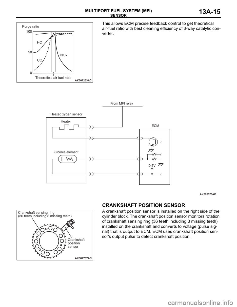
This allows ECM precise feedback control to get theoretical
air-fuel ratio with best cleaning efficiency of 3-way catalytic con
-
verter.
.
CRANKSHAFT POSITION SENSOR
A crankshaft position sensor is installed on the right side of the
cylinder block. The crankshaft position sensor monitors rotation
of crankshaft sensing ring (36 teeth including 3 missing teeth)
installed on the crankshaft and converts to voltage (pulse sig
-
nal) that is output to ECM. ECM uses crankshaft position sen-
sor's output pulse to detect crankshaft position.
.
AK602263AC
100
0HC
CONOx 50 Purge ratio
Theoretical air fuel ratio
AK602576AC
From MFI relay
Heated xygen sensor
Heater
Zirconia elementECM
0.5V
AK602737AC
Crankshaft
position
sensor Crankshaft sensing ring
(36 teeth including 3 missing teeth)
Page 116 of 241
ACTUATOR
MULTIPORT FUEL SYSTEM (MFI)13A-23
ACTUATORM2132002000353
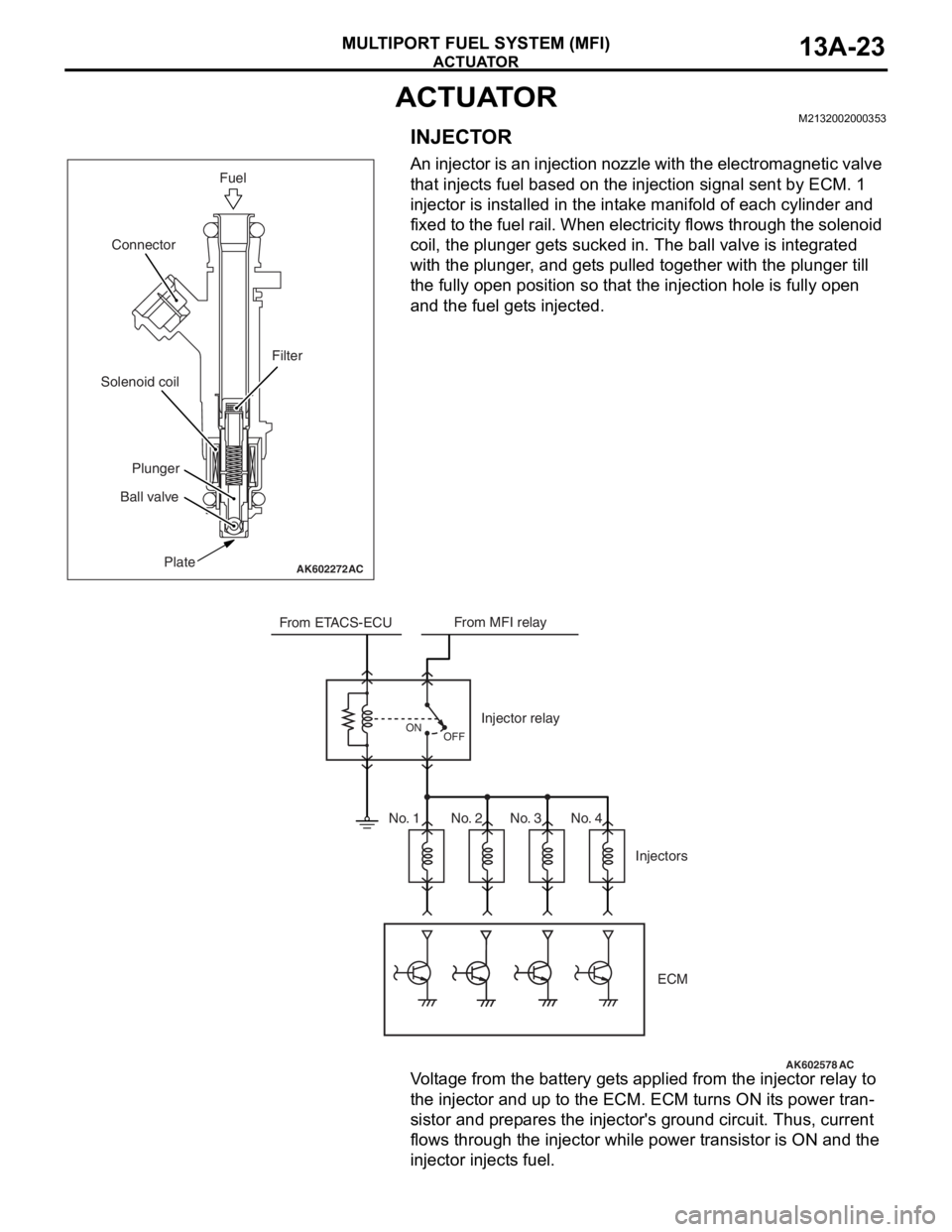
INJECTOR
An injector is an injection nozzle with the electromagnetic valve
that injects fuel based on the injection signal sent by ECM. 1
injector is installed in the intake manifold of each cylinder and
fixed to the fuel rail. When electricity flows through the solenoid
coil, the plunger gets sucked in. The ball valve is integrated
with the plunger, and gets pulled together with the plunger till
the fully open position so that the injection hole is fully open
and the fuel gets injected.
Voltage from the battery gets applied from the injector relay to
the injector and up to the ECM. ECM turns ON its power tran
-
sistor and prepares the injector's ground circuit. Thus, current
flows through the injector while power transistor is ON and the
injector injects fuel.
AK602272AC
Fuel
Plate Ball valvePlunger Solenoid coilConnector
Filter
AK602578
From ETACS-ECUFrom MFI relay
Injector relay
Injectors
OFF ON
ECM
AC
No. 1 No. 2 No. 3 No. 4
Page 117 of 241
ACTUATOR
MULTIPORT FUEL SYSTEM (MFI)13A-24
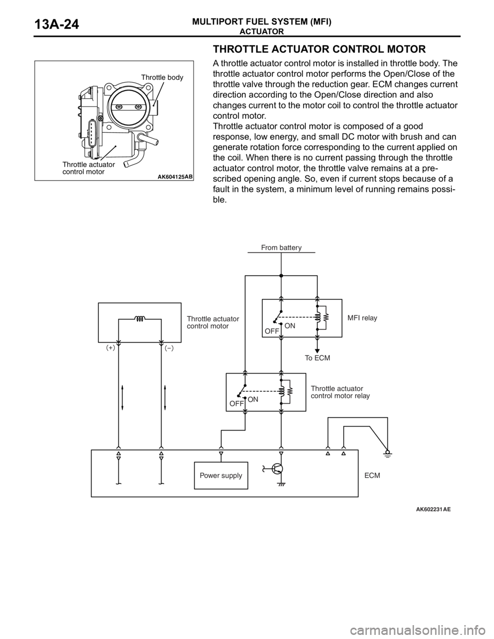
THROTTLE ACTUATOR CONTROL MOTOR
A throttle actuator control motor is installed in throttle body. The
throttle actuator control motor performs the Open/Close of the
throttle valve through the reduction gear. ECM changes current
direction according to the Open/Close direction and also
changes current to the motor coil to control the throttle actuator
control motor.
Throttle actuator control motor is composed of a good
response, low energy, and small DC motor with brush and can
generate rotation force corresponding to the current applied on
the coil. When there is no current passing through the throttle
actuator control motor, the throttle valve remains at a pre
-
scribed opening angle. So, even if current stops because of a
fault in the system, a minimum level of running remains possi
-
ble.
AK604125AB
Throttle body
Throttle actuator
control motor
AK602231
Throttle actuator
control motor
Throttle actuator
control motor relayMFI relay
To ECM
Power supplyOFFON
OFF
ON
AE
From battery
ECM
Page 118 of 241
ACTUATOR
MULTIPORT FUEL SYSTEM (MFI)13A-25
IGNITION COIL
Refer to GROUP 16 − Ignition Coil P.16-2.
EXHAUST GAS RECIRCULATION (EGR) VALVE
Refer to GROUP 17 − Emission Control − Exhaust Gas Recircu-
lation (EGR) System P.17-12.
EVAPORATIVE EMISSION PURGE SOLENOID
Refer to GROUP 17 − Emission Control − Evaporative Emission
Control System
P.17-11.
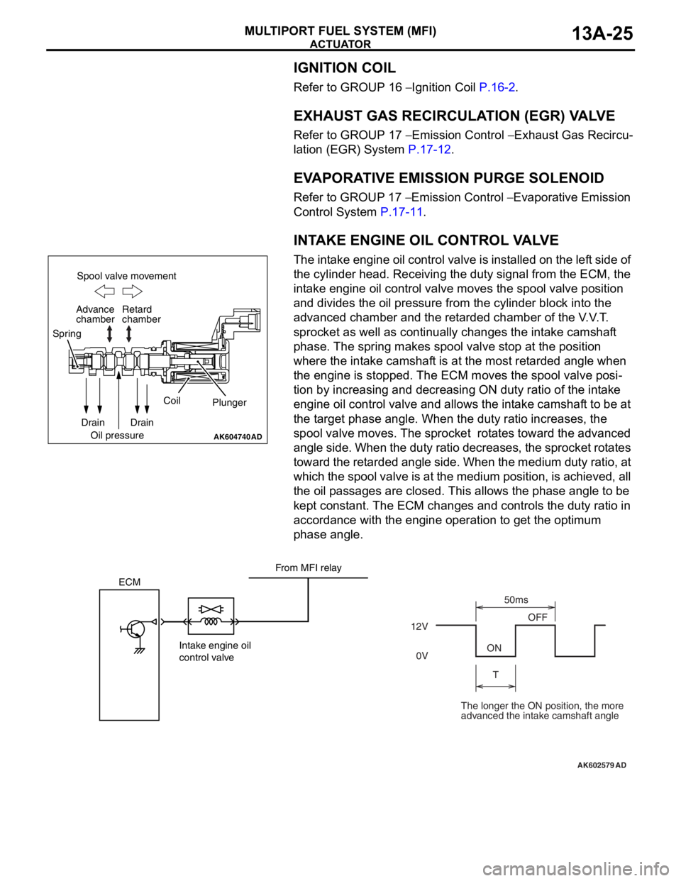
INTAKE ENGINE OIL CONTROL VALVE
The intake engine oil control valve is installed on the left side of
the cylinder head. Receiving the duty signal from the ECM, the
intake engine oil control valve moves the spool valve position
and divides the oil pressure from the cylinder block into the
advanced chamber and the retarded chamber of the V.V.T.
sprocket as well as continually changes the intake camshaft
phase. The spring makes spool valve stop at the position
where the intake camshaft is at the most retarded angle when
the engine is stopped. The ECM moves the spool valve posi
-
tion by increasing and decreasing ON duty ratio of the intake
engine oil control valve and allows the intake camshaft to be at
the target phase angle. When the duty ratio increases, the
spool valve moves. The sprocket rotates toward the advanced
angle side. When the duty ratio decreases, the sprocket rotates
toward the retarded angle side. When the medium duty ratio, at
which the spool valve is at the medium position, is achieved, all
the oil passages are closed. This allows the phase angle to be
kept constant. The ECM changes and controls the duty ratio in
accordance with the engine operation to get the optimum
phase angle.
AK604740AD
Spool valve movement
Retard
chamber
Spring
Drain
Oil pressureCoil
Plunger
Drain Advance
chamber
AK602579
ECM
Intake engine oil
control valve12VOFF
ON
T50ms
0V
AD
From MFI relay
The longer the ON position, the more
advanced the intake camshaft angle
Page 119 of 241
ACTUATOR
MULTIPORT FUEL SYSTEM (MFI)13A-26
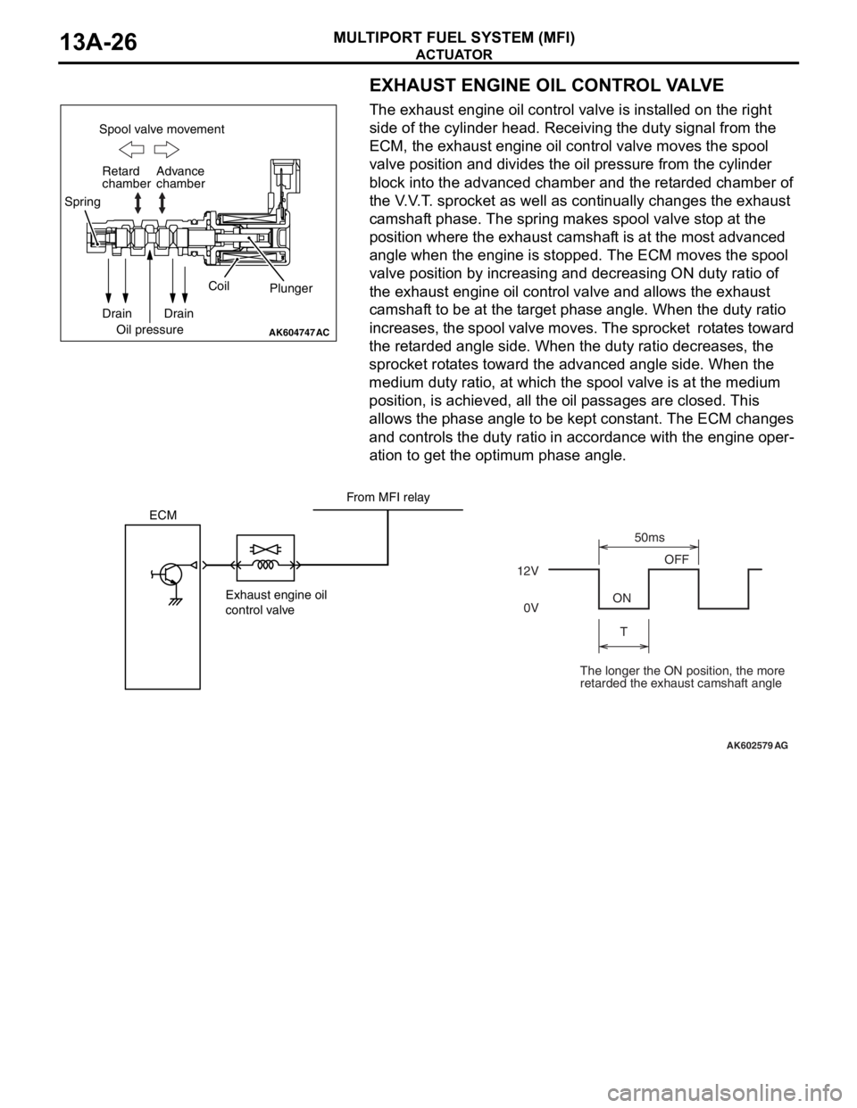
EXHAUST ENGINE OIL CONTROL VALVE
The exhaust engine oil control valve is installed on the right
side of the cylinder head. Receiving the duty signal from the
ECM, the exhaust engine oil control valve moves the spool
valve position and divides the oil pressure from the cylinder
block into the advanced chamber and the retarded chamber of
the V.V.T. sprocket as well as continually changes the exhaust
camshaft phase. The spring makes spool valve stop at the
position where the exhaust camshaft is at the most advanced
angle when the engine is stopped. The ECM moves the spool
valve position by increasing and decreasing ON duty ratio of
the exhaust engine oil control valve and allows the exhaust
camshaft to be at the target phase angle. When the duty ratio
increases, the spool valve moves. The sprocket rotates toward
the retarded angle side. When the duty ratio decreases, the
sprocket rotates toward the advanced angle side. When the
medium duty ratio, at which the spool valve is at the medium
position, is achieved, all the oil passages are closed. This
allows the phase angle to be kept constant. The ECM changes
and controls the duty ratio in accordance with the engine oper
-
ation to get the optimum phase angle.
AK604747
Spool valve movement
Retard
chamber
Spring
Drain
Oil pressureCoil
Plunger
Drain Advance
chamber
AC
AK602579
ECM
Exhaust engine oil
control valve12VOFF
ON
T50ms
0V
AG
From MFI relay
The longer the ON position, the more
retarded the exhaust camshaft angle