engine MITSUBISHI LANCER EVOLUTION X 2008 Service Manual
[x] Cancel search | Manufacturer: MITSUBISHI, Model Year: 2008, Model line: LANCER EVOLUTION X, Model: MITSUBISHI LANCER EVOLUTION X 2008Pages: 241, PDF Size: 8.26 MB
Page 81 of 241
SPARK PLUG
ENGINE ELECTRICAL16-3
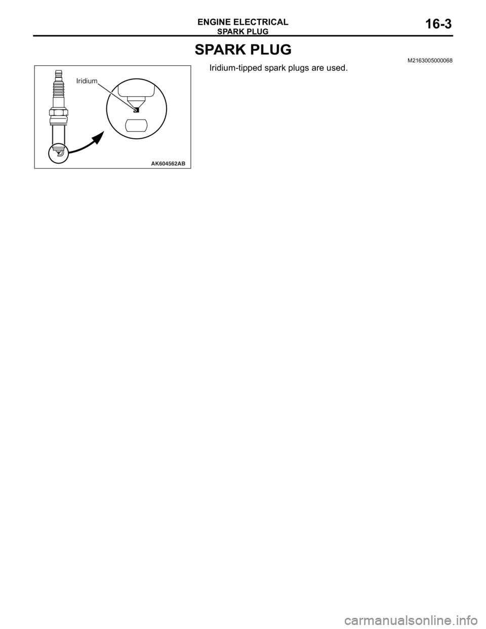
SPARK PLUGM2163005000068
Iridium-tipped spark plugs are used.
AK604562AB
Iridium
Page 84 of 241
AIR DUCT AND AIR CLEANER
INTAKE AND EXHAUST15-2
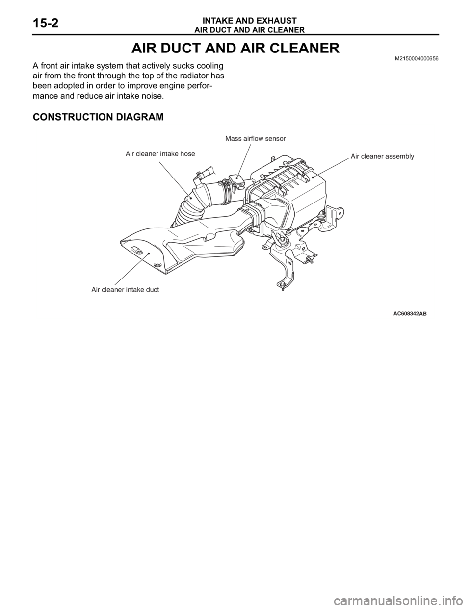
AIR DUCT AND AIR CLEANERM2150004000656
A front air intake system that actively sucks cooling
air from the front through the top of the radiator has
been adopted in order to improve engine perfor
-
mance and reduce air intake noise.
CONSTRUCTION DIAGRAM
AC608342AB
Air cleaner assembly Mass airflow sensor
Air cleaner intake hose
Air cleaner intake duct
Page 87 of 241
14-1
GROUP 14
ENGINE COOLING
CONTENTS
GENERAL INFORMATION . . . . . . . .14-2
WATER PASSAGE . . . . . . . . . . . . . .14-3
WATER PUMP . . . . . . . . . . . . . . . . . .14-3
Page 88 of 241

GENERAL INFORMATION
ENGINE COOLING14-2
GENERAL INFORMATIONM2140000100780
The cooling system is a water-cooled pressurized,
forced circulation type which offers the following fea
-
tures.
•To stabilize engine coolant temperature, the ther-
mostat is located at the coolant inlet port from the
radiator.
•To improve engine cooling performance and save
weight, a plastic tank and aluminum radiator fins
are used.
SPECIFICATIONS
CONSTRUCTION DIAGRAM
ItemSpecification
Cooling methodWater-cooled pressurized, forced
circulation with electrical fan
RadiatorTy p ePressurized corrugate type
Performance kJ/h (kcal/h)222,480 (53,148)
Water pumpTy p eCentrifugal impeller
Drive methodDrive belt
ThermostatTy p eWax pellet with jiggle valve
Valve open temperature °C (°F)82 (180)
AC608448
Condenser fan motor Radiator assemblyRadiator upper hose
assembly
Radiator condenser
tank assembly Radiator fan motor
Cooling fan shroud
Radiator lower hose Transmission oil
cooler line hose
and tube assembly
AB
Page 89 of 241
WATER PASSAGE
ENGINE COOLING14-3
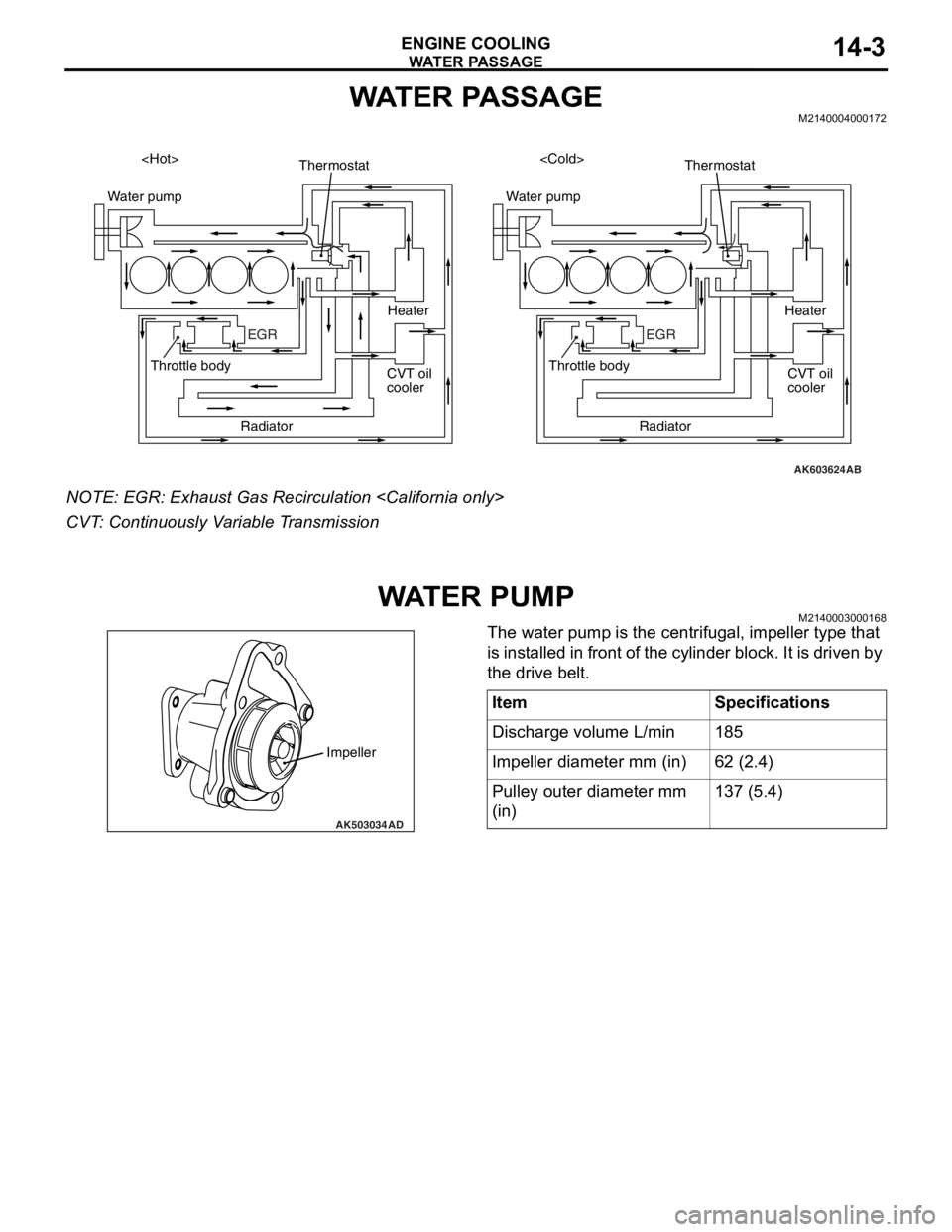
WATER PASSAGEM2140004000172
NOTE: EGR: Exhaust Gas Recirculation
CVT: Continuously Variable Transmission
WAT E R P U M PM2140003000168
The water pump is the centrifugal, impeller type that
is installed in front of the cylinder block. It is driven by
the drive belt.
AK603624
Water pump
EGR
AB
Thermostat
Radiator Throttle body
CVT oil
coolerHeater
Water pump
EGR
Thermostat
Radiator Throttle body
CVT oil
cooler Heater
AK503034
Impeller
AD
ItemSpecifications
Discharge volume L/min185
Impeller diameter mm (in)62 (2.4)
Pulley outer diameter mm
(in)137 (5.4)
Page 92 of 241
GENERAL INFORMATION
FUEL SUPPLY13B-2
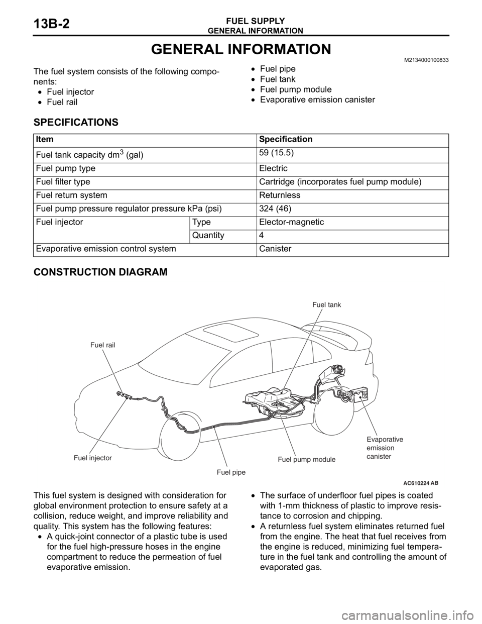
GENERAL INFORMATIONM2134000100833.The fuel system consists of the following compo-
nents:
•Fuel injector
•Fuel rail
•Fuel pipe
•Fuel tank
•Fuel pump module
•Evaporative emission canister
SPECIFICATIONS
CONSTRUCTION DIAGRAM
This fuel system is designed with consideration for
global environment protection to ensure safety at a
collision, reduce weight, and improve reliability and
quality. This system has the following features:
•A quick-joint connector of a plastic tube is used
for the fuel high-pressure hoses in the engine
compartment to reduce the permeation of fuel
evaporative emission.
•The surface of underfloor fuel pipes is coated
with 1-mm thickness of plastic to improve resis
-
tance to corrosion and chipping.
•A returnless fuel system eliminates returned fuel
from the engine. The heat that fuel receives from
the engine is reduced, minimizing fuel tempera
-
ture in the fuel tank and controlling the amount of
evaporated gas.
ItemSpecification
Fuel tank capacity dm3 (gal)59 (15.5)
Fuel pump typeElectric
Fuel filter typeCartridge (incorporates fuel pump module)
Fuel return systemReturnless
Fuel pump pressure regulator pressure kPa (psi)324 (46)
Fuel injectorTy p eElector-magnetic
Quantity4
Evaporative emission control systemCanister
AC610224
Fuel rail
Fuel injector
Fuel pipeFuel pump moduleEvaporative
emission
canister Fuel tank
AB
Page 96 of 241

GENERAL DESCRIPTION
MULTIPORT FUEL SYSTEM (MFI)13A-2
GENERAL DESCRIPTIONM2132000101283
Although the control systems are basically the same as those of 2.4L engine used in the GALANT, the follow-
ing improvements have been added.
Improvement / AdditionsRemark
MIVEC, continuously and variably control the intake
valve timing and exhaust valve timing, is used.System optimally control the timing of the intake
valve and exhaust valve in accordance with the
engine speed and load.
Addition of heated oxygen sensor (3rd)
Page 97 of 241
GENERAL DESCRIPTION
MULTIPORT FUEL SYSTEM (MFI)13A-3
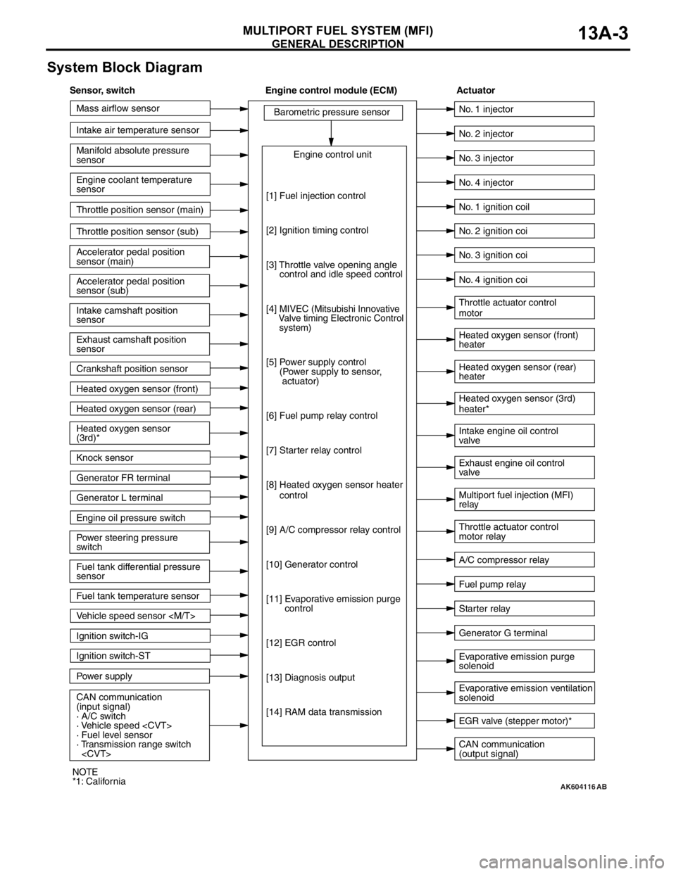
System Block Diagram
AK604116
Mass airflow sensor
Intake air temperature sensor
Intake camshaft position
sensor
Exhaust camshaft position
sensor
Crankshaft position sensor Throttle position sensor (main)
Throttle position sensor (sub)
Accelerator pedal position
sensor (sub) Accelerator pedal position
sensor (main) Engine coolant temperature
sensor Manifold absolute pressure
sensor
Heated oxygen sensor (front)
Heated oxygen sensor (rear)
Power steering pressure
switch Engine oil pressure switch Generator L terminal
Ignition switch-ST
Power supply Ignition switch-IG
CAN communication
(input signal)
· A/C switch
· Vehicle speed
· Fuel level sensor
· Transmission range switch
sensor Heated oxygen sensor
(3rd)*
Knock sensor
Generator FR terminal
Fuel tank temperature sensor
Vehicle speed sensor
[1] Fuel injection control
[2] Ignition timing control
[3] Throttle valve opening angle
control and idle speed control
[4]
MIVEC (Mitsubishi Innovative
Valve timing Electronic Control
system)
[5] Power supply control
(Power supply to sensor,
actuator)
[6] Fuel pump relay control
[7] Starter relay control
[8] Heated oxygen sensor heater
control
[9] A/C compressor relay control
[10] Generator control
[11] Evaporative emission purge
control
[12] EGR control
[13] Diagnosis output
[14] RAM data transmission
CAN communication
(output signal) Intake engine oil control
valve
A/C compressor relay No. 2 injector
No. 3 injector
No. 4 injector
Heated oxygen sensor (front)
heater
Heated oxygen sensor (rear)
heater Throttle actuator control
motor
Throttle actuator control
motor relay No. 1 injector
No. 1 ignition coil
No. 2 ignition coi
No. 3 ignition coi
No. 4 ignition coi
Fuel pump relay
Generator G terminal Heated oxygen sensor (3rd)
heater*
Multiport fuel injection (MFI)
relay Exhaust engine oil control
valve
Evaporative emission ventilation
solenoid Evaporative emission purge
solenoid
EGR valve (stepper motor)*
Starter relay
AB
Sensor, switch Engine control module (ECM) Actuator
NOTE
*1: California
Page 98 of 241
GENERAL DESCRIPTION
MULTIPORT FUEL SYSTEM (MFI)13A-4
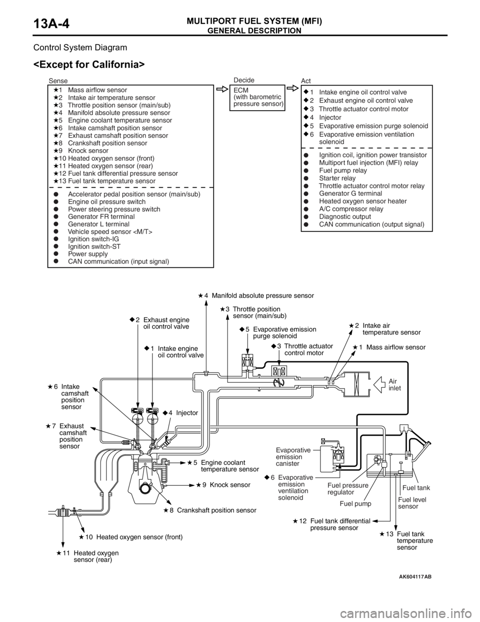
Control System Diagram
AK604117
Fuel level
sensorFuel tank Air
inlet
2 Exhaust engine
oil control valve
1 Intake engine
oil control valve4 Manifold absolute pressure sensor
2 Intake air
temperature sensor
1 Mass airflow sensor
6 Intake
camshaft
position
sensor
7 Exhaust
camshaft
position
sensor
3 Throttle position
sensor (main/sub)
5 Evaporative emission
purge solenoid
3 Throttle actuator
control motor
12 Fuel tank differential
pressure sensor
13 Fuel tank
temperature
sensor10 Heated oxygen sensor (front)
11 Heated oxygen
sensor (rear)
8 Crankshaft position sensor5 Engine coolant
temperature sensor
9 Knock sensor
4 Injector
Fuel pump Fuel pressure
regulator Evaporative
emission
canister
6 Evaporative
emission
ventilation
solenoid
1 Mass airflow sensor
2 Intake air temperature sensor
3 Throttle position sensor (main/sub)
4 Manifold absolute pressure sensor
5 Engine coolant temperature sensor
6 Intake camshaft position sensor
7 Exhaust camshaft position sensor
8 Crankshaft position sensor
9 Knock sensor
10 Heated oxygen sensor (front)
11 Heated oxygen sensor (rear)
12 Fuel tank differential pressure sensor
13 Fuel tank temperature sensor
Ignition switch-IG
Ignition switch-ST
Power supply
CAN communication (input signal)1 Intake engine oil control valve
2 Exhaust engine oil control valve
3 Throttle actuator control motor
4 Injector
5 Evaporative emission purge solenoid
6 Evaporative emission ventilation
solenoid
Ignition coil, ignition power transistor
Multiport fuel injection (MFI) relay
Fuel pump relay
Starter relay
Throttle actuator control motor relay
Generator G terminal
Heated oxygen sensor heater
A/C compressor relay
Diagnostic output
CAN communication (output signal) SenseAct
Engine oil pressure switch
Power steering pressure switch
Generator FR terminal
Generator L terminal
Vehicle speed sensor
Decide
ECM
(with barometric
pressure sensor)
AB
Page 99 of 241
GENERAL DESCRIPTION
MULTIPORT FUEL SYSTEM (MFI)13A-5
AK604118
Fuel tank
Fuel level
sensor Air
inlet
2 Exhaust engine
oil control valve
1 Intake engine
oil control valve4 Manifold absolute pressure sensor
2 Intake air
temperature sensor
1 Mass airflow sensor
6 Intake
camshaft
position
sensor
7 Exhaust
camshaft
position
sensor
3 Throttle position
sensor (main/sub)
5 Evaporative emission
purge solenoid
3 Throttle actuator
control motor
12 Fuel tank differential
pressure sensor
13 Fuel tank
temperature
sensor11 Heated oxygen sensor (rear)
10 Heated
oxygen
sensor
(front)
12 Heated oxygen sensor (3rd)
8 Crankshaft position sensor5 Engine
coolant
temperature
sensor
9 Knock sensor
4 Injector
Fuel pump Fuel pressure
regulator Evaporative
emission
canister
6 Evaporative
emission
ventilation
solenoid
7 EGR valve
(stepper motor)
1 Mass airflow sensor
2 Intake air temperature sensor
3 Throttle position sensor (main/sub)
4 Manifold absolute pressure sensor
5 Engine coolant temperature sensor
6 Intake camshaft position sensor
7 Exhaust camshaft position sensor
8 Crankshaft position sensor
9 Knock sensor
10 Heated oxygen sensor (front)
11 Heated oxygen sensor (rear)
12 Heated oxygen sensor (3rd)
13 Fuel tank differential pressure sensor
14 Fuel tank temperature sensor
Ignition switch-IG
Ignition switch-ST
Power supply
CAN communication (input signal)1 Intake engine oil control valve
2 Exhaust engine oil control valve
3 Throttle actuator control motor
4 Injector
5 Evaporative emission purge solenoid
6 Evaporative emission ventilation
solenoid
7 EGR valve (stepper motor)
Ignition coil, ignition power transistor
Multiport fuel injection (MFI) relay
Fuel pump relay
Starter relay
Throttle actuator control motor relay
Generator G terminal
Heated oxygen sensor heater
A/C compressor relay
Diagnostic output
CAN communication (output signal) SenseAct
Engine oil pressure switch
Power steering pressure switch
Generator FR terminal
Generator L terminal
Vehicle speed sensor
Decide
ECM
(with barometric
pressure sensor)
AB