engine MITSUBISHI LANCER EVOLUTION X 2008 Repair Manual
[x] Cancel search | Manufacturer: MITSUBISHI, Model Year: 2008, Model line: LANCER EVOLUTION X, Model: MITSUBISHI LANCER EVOLUTION X 2008Pages: 241, PDF Size: 8.26 MB
Page 100 of 241
CONTROL UNIT
MULTIPORT FUEL SYSTEM (MFI)13A-6
CONTROL UNITM2132021500153
ENGINE CONTROL MODULE (ECM)
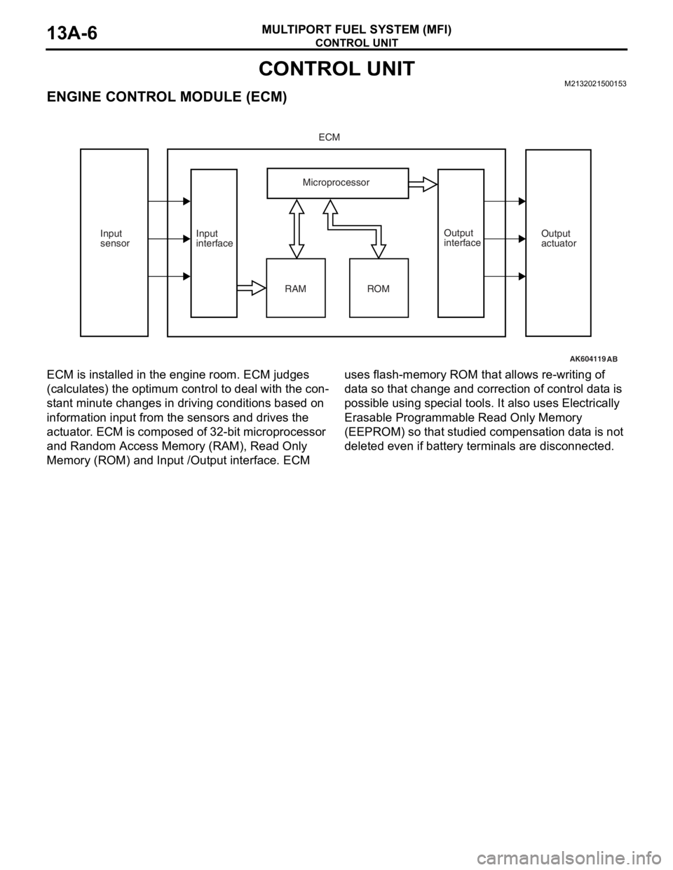
ECM is installed in the engine room. ECM judges
(calculates) the optimum control to deal with the con
-
stant minute changes in driving conditions based on
information input from the sensors and drives the
actuator. ECM is composed of 32-bit microprocessor
and Random Access Memory (RAM), Read Only
Memory (ROM) and Input /Output interface. ECM uses flash-memory ROM that allows re-writing of
data so that change and correction of control data is
possible using special tools. It also uses Electrically
Erasable Programmable Read Only Memory
(EEPROM) so that studied compensation data is not
deleted even if battery terminals are disconnected.
ECM CONNECTOR INPUT/OUTPUT PIN ARRANGEMENT
NOTE: *: California
AK604119
ECM
Microprocessor
RAM Input
interfaceOutput
interface Input
sensorOutput
actuator
AB
ROM
AK602565AC
1 2 3 4 5 6 7 8 9 10 11 1213 14 15 16
17 18 19 20 21 91
90
89
87
86
84 85
83 82
88 92 93 94
95 96 97 98 99
109
108
107 106
105
104
103
102
112 113 114 115 116 117 118
100 101
111
110
41
40
39
38
37
36
35
34
33 32
31
30
29
28
27
26
25
24
23
2260
59
58
57
56
55
54
53
52
51
50
49 48
47
46
45
44
43
4263
61 62 6471 72 73 74 75 76 77 78 79 80 81
1Intake engine oil control valve2No.1 injector
3No.2 injector4Ignition coil No.1 (ignition power transistor)
5Ignition coil No.2 (ignition power transistor)6Starter active signal
7Exhaust camshaft position sensor8Crankshaft position sensor
9Sensor supplied voltage10Throttle position sensor (main)
11Throttle position sensor (sub)12Power supply voltage applied to throttle
position sensor
13Throttle position sensor ground14Intake camshaft position sensor
Page 101 of 241
SENSOR
MULTIPORT FUEL SYSTEM (MFI)13A-8
SENSORM2132001000565.
MASS AIRFLOW SENSOR
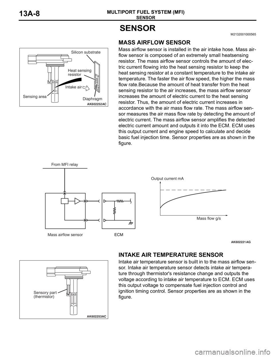
Mass airflow sensor is installed in the air intake hose. Mass air-
flow sensor is composed of an extremely small heatsensing
resistor. The mass airflow sensor controls the amount of elec
-
tric current flowing into the heat sensing resistor to keep the
heat sensing resistor at a constant temperature to the intake air
temperature. The faster the air flow speed, the higher the mass
flow rate.Because the amount of heat transfer from the heat
sensing resistor to the air increases, the mass airflow sensor
increases the amount of electric current to the heat sensing
resistor. Thus, the amount of electric current increases in
accordance with the air mass flow rate. The mass airflow sen
-
sor measures the air mass flow rate by detecting the amount of
electric current. The mass airflow sensor amplifies the detected
electric current amount and outputs it into the ECM. ECM uses
this output current and engine speed to calculate and decide
basic fuel injection time. Sensor properties are as shown in the
figure.
.
INTAKE AIR TEMPERATURE SENSOR
Intake air temperature sensor is built in to the mass airflow sen-
sor. Intake air temperature sensor detects intake air tempera-
ture through thermistor's resistance change and outputs the
voltage according to intake air temperature to ECM. ECM uses
this output voltage to compensate fuel injection control and
ignition timing control. Sensor properties are as shown in the
figure.
AK602252AC
Sensing areaSilicon substrate
Heat sensing
resistor
Intake air
Diaphragm
AK602221AG
From MFI relay
Mass airflow sensorECMOutput current mA
Mass flow g/s
AK602253AC
Sensory part
(thermistor)
Page 103 of 241
SENSOR
MULTIPORT FUEL SYSTEM (MFI)13A-10
ENGINE COOLANT TEMPERATURE SENSOR
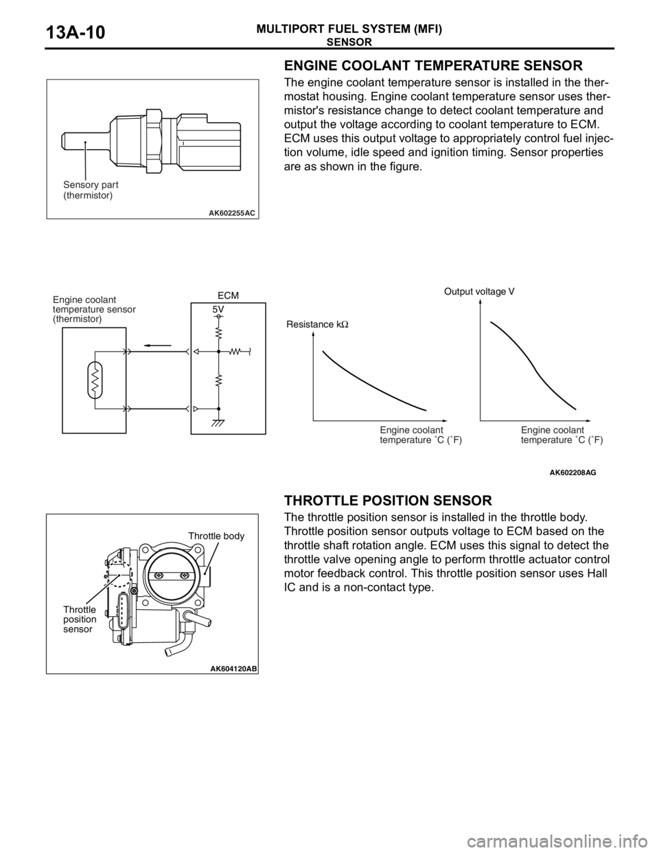
The engine coolant temperature sensor is installed in the ther-
mostat housing. Engine coolant temperature sensor uses ther-
mistor's resistance change to detect coolant temperature and
output the voltage according to coolant temperature to ECM.
ECM uses this output voltage to appropriately control fuel injec
-
tion volume, idle speed and ignition timing. Sensor properties
are as shown in the figure.
.
THROTTLE POSITION SENSOR
The throttle position sensor is installed in the throttle body.
Throttle position sensor outputs voltage to ECM based on the
throttle shaft rotation angle. ECM uses this signal to detect the
throttle valve opening angle to perform throttle actuator control
motor feedback control. This throttle position sensor uses Hall
IC and is a non-contact type.
.
AK602255AC
Sensory part
(thermistor)
AK602208
Engine coolant
temperature �C (�F)
AG
Output voltage V
5V Engine coolant
temperature sensor
(thermistor)
Engine coolant
temperature �C (�F) ECM
Resistance kΩ
AK604120AB
Throttle body
Throttle
position
sensor
Page 107 of 241
SENSOR
MULTIPORT FUEL SYSTEM (MFI)13A-14
.
HEATED OXYGEN SENSOR (except centor
exhaust pipe heated oxygen sensor
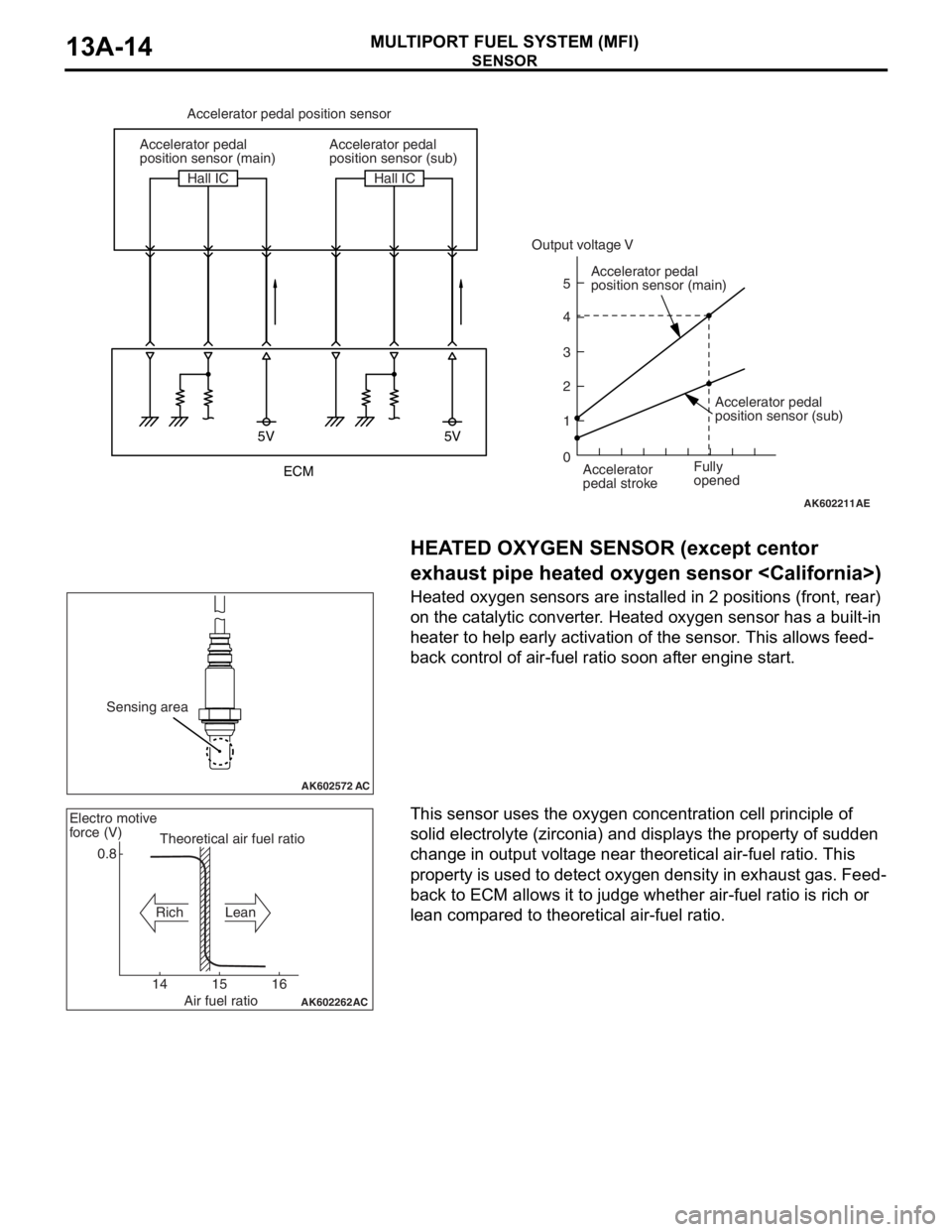
Heated oxygen sensors are installed in 2 positions (front, rear)
on the catalytic converter. Heated oxygen sensor has a built-in
heater to help early activation of the sensor. This allows feed
-
back control of air-fuel ratio soon after engine start.
.
This sensor uses the oxygen concentration cell principle of
solid electrolyte (zirconia) and displays the property of sudden
change in output voltage near theoretical air-fuel ratio. This
property is used to detect oxygen density in exhaust gas. Feed
-
back to ECM allows it to judge whether air-fuel ratio is rich or
lean compared to theoretical air-fuel ratio.
AK602211
5V 5V
5
4
3
2
1
0
AE
Accelerator pedal position sensor
Accelerator pedal
position sensor (main)
Accelerator pedal
position sensor (main)
Accelerator
pedal stroke Accelerator pedal
position sensor (sub)
Accelerator pedal
position sensor (sub) Hall IC Hall IC
Fully
opened
Output voltage V
ECM
AK602572 AC
Sensing area
AK602262
AC
0.8
14 15 16Theoretical air fuel ratio Electro motive
force (V)
Rich Lean
Air fuel ratio
Page 110 of 241
SENSOR
MULTIPORT FUEL SYSTEM (MFI)13A-17
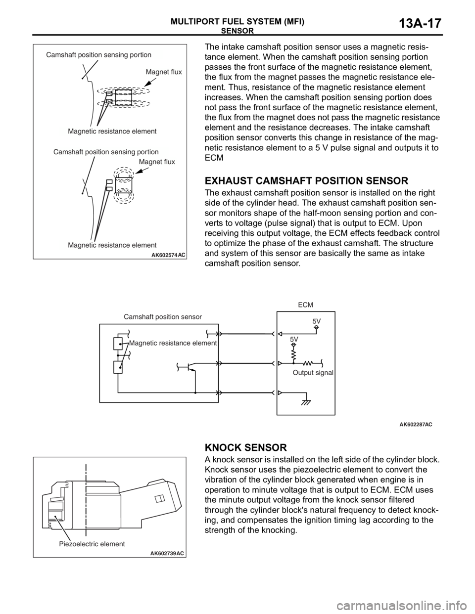
The intake camshaft position sensor uses a magnetic resis-
tance element. When the camshaft position sensing portion
passes the front surface of the magnetic resistance element,
the flux from the magnet passes the magnetic resistance ele
-
ment. Thus, resistance of the magnetic resistance element
increases. When the camshaft position sensing portion does
not pass the front surface of the magnetic resistance element,
the flux from the magnet does not pass the magnetic resistance
element and the resistance decreases. The intake camshaft
position sensor converts this change in resistance of the mag
-
netic resistance element to a 5 V pulse signal and outputs it to
ECM
.
EXHAUST CAMSHAFT POSITION SENSOR
The exhaust camshaft position sensor is installed on the right
side of the cylinder head. The exhaust camshaft position sen
-
sor monitors shape of the half-moon sensing portion and con-
verts to voltage (pulse signal) that is output to ECM. Upon
receiving this output voltage, the ECM effects feedback control
to optimize the phase of the exhaust camshaft. The structure
and system of this sensor are basically the same as intake
camshaft position sensor.
.
.
KNOCK SENSOR
A knock sensor is installed on the left side of the cylinder block.
Knock sensor uses the piezoelectric element to convert the
vibration of the cylinder block generated when engine is in
operation to minute voltage that is output to ECM. ECM uses
the minute output voltage from the knock sensor filtered
through the cylinder block's natural frequency to detect knock
-
ing, and compensates the ignition timing lag according to the
strength of the knocking.
AK602574AC
Camshaft position sensing portion
Camshaft position sensing portionMagnetic resistance element
Magnetic resistance elementMagnet flux
Magnet flux
AK602287
5V5V Camshaft position sensorECM
Output signal Magnetic resistance element
AC
AK602739
Piezoelectric element
AC
Page 111 of 241
SENSOR
MULTIPORT FUEL SYSTEM (MFI)13A-18
.
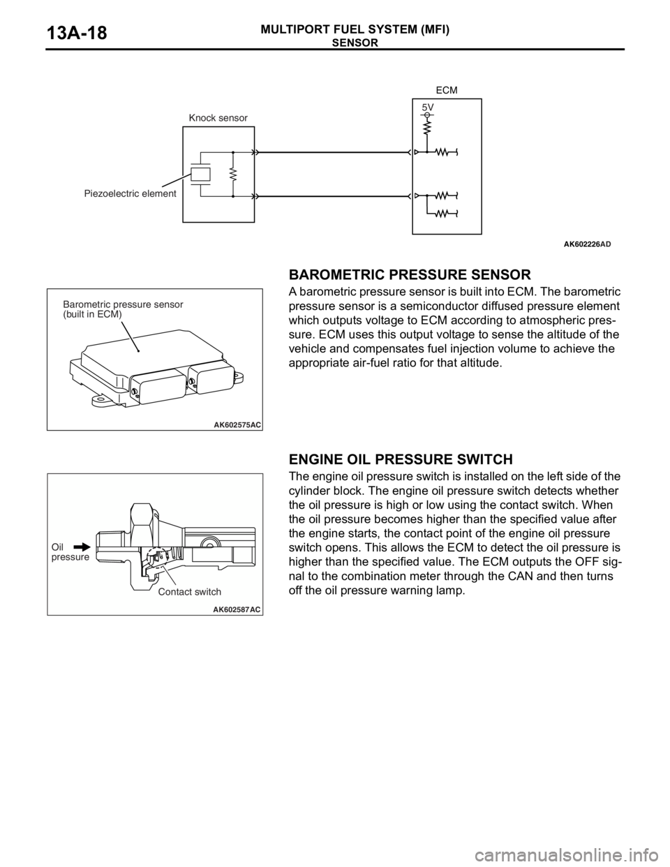
BAROMETRIC PRESSURE SENSOR
A barometric pressure sensor is built into ECM. The barometric
pressure sensor is a semiconductor diffused pressure element
which outputs voltage to ECM according to atmospheric pres
-
sure. ECM uses this output voltage to sense the altitude of the
vehicle and compensates fuel injection volume to achieve the
appropriate air-fuel ratio for that altitude.
.
ENGINE OIL PRESSURE SWITCH
The engine oil pressure switch is installed on the left side of the
cylinder block. The engine oil pressure switch detects whether
the oil pressure is high or low using the contact switch. When
the oil pressure becomes higher than the specified value after
the engine starts, the contact point of the engine oil pressure
switch opens. This allows the ECM to detect the oil pressure is
higher than the specified value. The ECM outputs the OFF sig
-
nal to the combination meter through the CAN and then turns
off the oil pressure warning lamp.
AK602226AD
5V
Knock sensor
Piezoelectric elementECM
AK602575AC
Barometric pressure sensor
(built in ECM)
AK602587AC
Oil
pressure
Contact switch
Page 112 of 241
SENSOR
MULTIPORT FUEL SYSTEM (MFI)13A-19
.
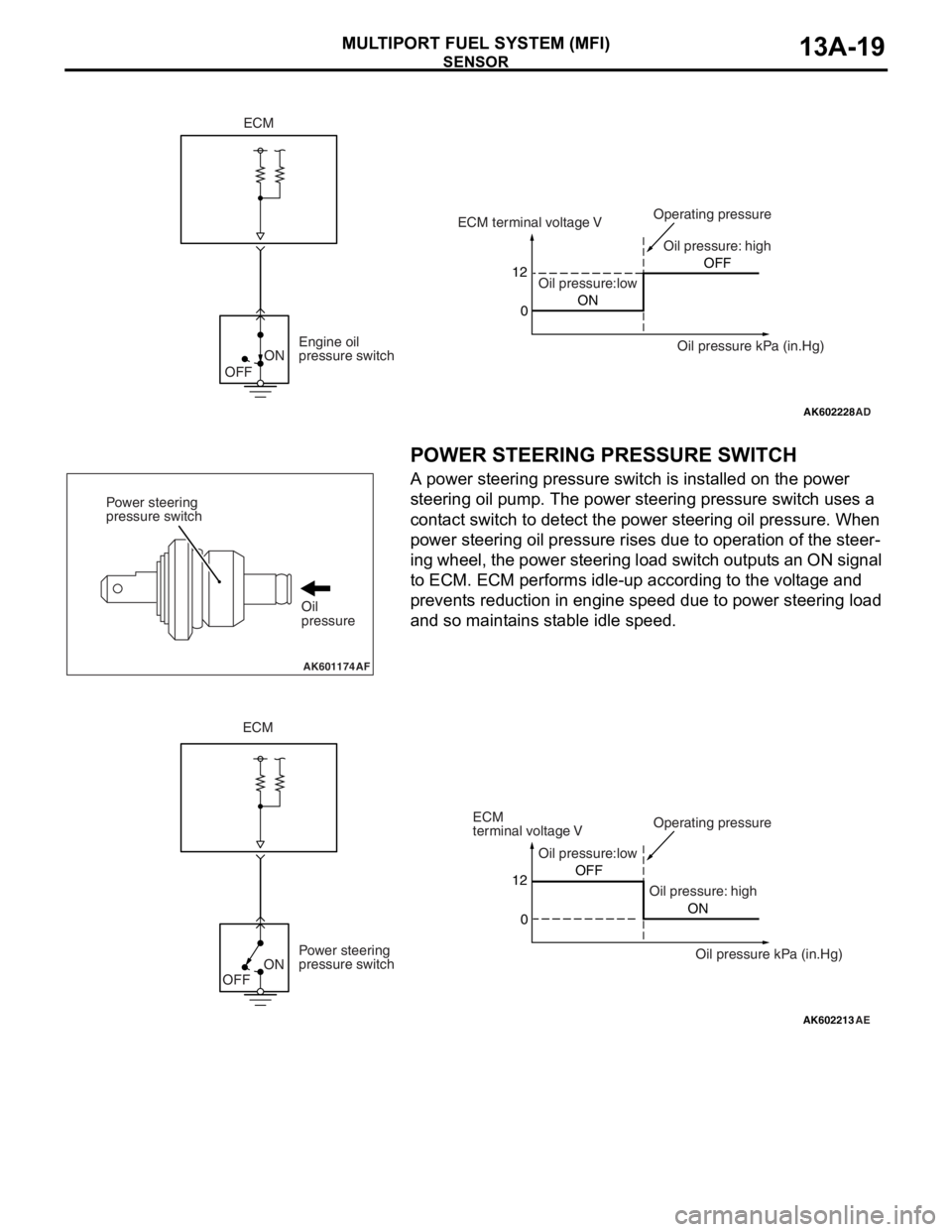
POWER STEERING PRESSURE SWITCH
A power steering pressure switch is installed on the power
steering oil pump. The power steering pressure switch uses a
contact switch to detect the power steering oil pressure. When
power steering oil pressure rises due to operation of the steer
-
ing wheel, the power steering load switch outputs an ON signal
to ECM. ECM performs idle-up according to the voltage and
prevents reduction in engine speed due to power steering load
and so maintains stable idle speed.
.
AK602228
ON
OFF
AD
12
0ONOFF ECM terminal voltage V
Oil pressure:lowOil pressure: high Operating pressure
Oil pressure kPa (in.Hg) Engine oil
pressure switch
ECM
AK601174AF
Power steering
pressure switch
Oil
pressure
AK602213
ON
OFF
AE
Oil pressure:low
Oil pressure: highOperating pressure
Power steering
pressure switch12
0OFF
ON
ECM
ECM
terminal voltage V
Oil pressure kPa (in.Hg)
Page 118 of 241
ACTUATOR
MULTIPORT FUEL SYSTEM (MFI)13A-25
IGNITION COIL
Refer to GROUP 16 − Ignition Coil P.16-2.
EXHAUST GAS RECIRCULATION (EGR) VALVE
Refer to GROUP 17 − Emission Control − Exhaust Gas Recircu-
lation (EGR) System P.17-12.
EVAPORATIVE EMISSION PURGE SOLENOID
Refer to GROUP 17 − Emission Control − Evaporative Emission
Control System
P.17-11.
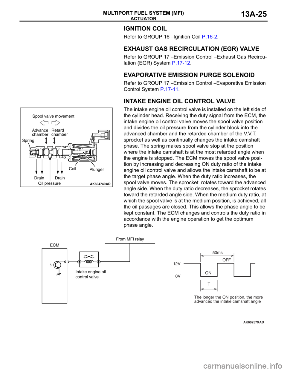
INTAKE ENGINE OIL CONTROL VALVE
The intake engine oil control valve is installed on the left side of
the cylinder head. Receiving the duty signal from the ECM, the
intake engine oil control valve moves the spool valve position
and divides the oil pressure from the cylinder block into the
advanced chamber and the retarded chamber of the V.V.T.
sprocket as well as continually changes the intake camshaft
phase. The spring makes spool valve stop at the position
where the intake camshaft is at the most retarded angle when
the engine is stopped. The ECM moves the spool valve posi
-
tion by increasing and decreasing ON duty ratio of the intake
engine oil control valve and allows the intake camshaft to be at
the target phase angle. When the duty ratio increases, the
spool valve moves. The sprocket rotates toward the advanced
angle side. When the duty ratio decreases, the sprocket rotates
toward the retarded angle side. When the medium duty ratio, at
which the spool valve is at the medium position, is achieved, all
the oil passages are closed. This allows the phase angle to be
kept constant. The ECM changes and controls the duty ratio in
accordance with the engine operation to get the optimum
phase angle.
AK604740AD
Spool valve movement
Retard
chamber
Spring
Drain
Oil pressureCoil
Plunger
Drain Advance
chamber
AK602579
ECM
Intake engine oil
control valve12VOFF
ON
T50ms
0V
AD
From MFI relay
The longer the ON position, the more
advanced the intake camshaft angle
Page 119 of 241
ACTUATOR
MULTIPORT FUEL SYSTEM (MFI)13A-26
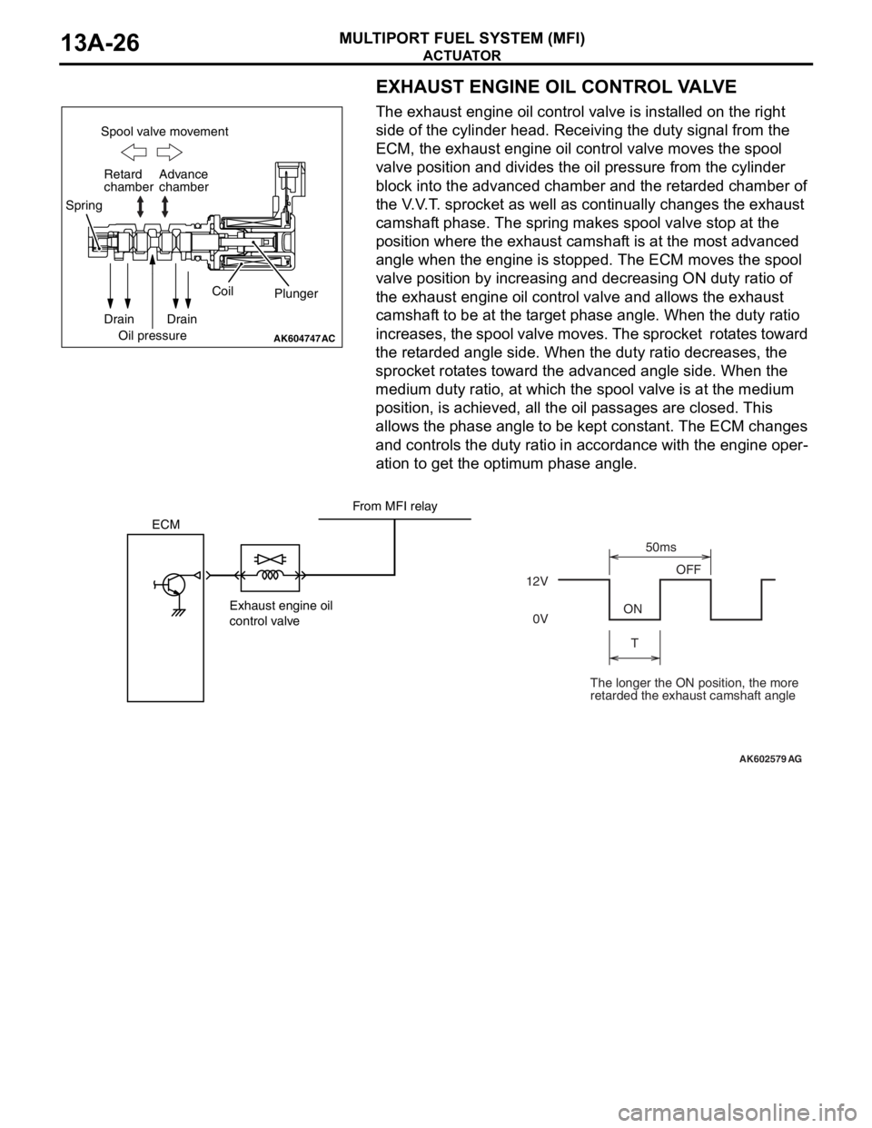
EXHAUST ENGINE OIL CONTROL VALVE
The exhaust engine oil control valve is installed on the right
side of the cylinder head. Receiving the duty signal from the
ECM, the exhaust engine oil control valve moves the spool
valve position and divides the oil pressure from the cylinder
block into the advanced chamber and the retarded chamber of
the V.V.T. sprocket as well as continually changes the exhaust
camshaft phase. The spring makes spool valve stop at the
position where the exhaust camshaft is at the most advanced
angle when the engine is stopped. The ECM moves the spool
valve position by increasing and decreasing ON duty ratio of
the exhaust engine oil control valve and allows the exhaust
camshaft to be at the target phase angle. When the duty ratio
increases, the spool valve moves. The sprocket rotates toward
the retarded angle side. When the duty ratio decreases, the
sprocket rotates toward the advanced angle side. When the
medium duty ratio, at which the spool valve is at the medium
position, is achieved, all the oil passages are closed. This
allows the phase angle to be kept constant. The ECM changes
and controls the duty ratio in accordance with the engine oper
-
ation to get the optimum phase angle.
AK604747
Spool valve movement
Retard
chamber
Spring
Drain
Oil pressureCoil
Plunger
Drain Advance
chamber
AC
AK602579
ECM
Exhaust engine oil
control valve12VOFF
ON
T50ms
0V
AG
From MFI relay
The longer the ON position, the more
retarded the exhaust camshaft angle
Page 120 of 241
ACTUATOR
MULTIPORT FUEL SYSTEM (MFI)13A-27
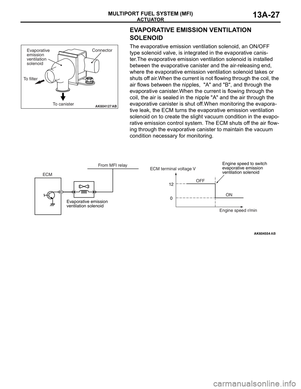
EVAPORATIVE EMISSION VENTILATION
SOLENOID
The evaporative emission ventilation solenoid, an ON/OFF
type solenoid valve, is integrated in the evaporative canis
-
ter.The evaporative emission ventilation solenoid is installed
between the evaporative canister and the air-releasing end,
where the evaporative emission ventilation solenoid takes or
shuts off air.When the current is not flowing through the coil, the
air flows between the nipples, "A" and "B", and through the
evaporative canister.When the current is flowing through the
coil, the air is sealed in the nipple "A" and the air through the
evaporative canister is shut off.When monitoring the evapora
-
tive leak, the ECM turns the evaporative emission ventilation
solenoid on to create the slight vacuum condition in the evapo
-
rative emission control system. The ECM shuts off the air flow-
ing through the evaporative canister to maintain the vacuum
condition necessary for monitoring.
AK604127ABTo canisterConnector
Evaporative
emission
ventilation
solenoid
To filter
AK604554
12
0
AB
OFF
ON ECMECM terminal voltage V
Engine speed r/min From MFI relay
Evaporative emission
ventilation solenoidEngine speed to switch
evaporative emission
ventilation solenoid