sensor MITSUBISHI LANCER EVOLUTION X 2008 Repair Manual
[x] Cancel search | Manufacturer: MITSUBISHI, Model Year: 2008, Model line: LANCER EVOLUTION X, Model: MITSUBISHI LANCER EVOLUTION X 2008Pages: 241, PDF Size: 8.26 MB
Page 132 of 241

THROTTLE VALVE OPENING ANGLE CONTROL AND IDLE SPEED CONTROL
MULTIPORT FUEL SYSTEM (MFI)13A-39
List of main compensations for throttle valve opening angle and idle speed control
Initialize control
After ignition switch turns OFF, ECM drives the throt-
tle valve from fully closed position to fully open posi-
tion and records the fully closed/open studied value
of the throttle position sensor (main and sub) output
signals. The recorded studied values are used as
studied value compensation for compensating basic
target opening angle when the engine is started next.
CompensationsContent
Stable idle compensation (immediately after start)In order to stabilize idle speed immediately after
start, target opening angle is kept big and then
gradually reduced. Compensation values are set
based on the engine coolant temperature.
Rotation speed feedback compensation (while
idling)In case there is a difference between the target idle
speed and actual engine speed, ECM
compensates the throttle valve opening angle
based on that difference.
Atmospheric pressure compensationAt high altitudes atmospheric pressure is less and
the intake air density is low. So, the target opening
angle is compensated based on atmospheric
pressure.
Engine coolant temperature compensationCompensation is made according to the engine
coolant temperature. The lower the engine coolant
temperature the greater the throttle valve opening
angle.
Electric load compensationThrottle valve opening angle is compensated
according to electric load. The greater the electric
load, the greater the throttle valve opening angle.
Compensation when shift is in D range
to some other range, throttle valve opening angle is
increased to prevent reduction in engine speed.
Compensation when A/C is functioningThrottle valve opening angle is compensated
according to functioning of A/C compressor. While
A/C compressor is being driven, the throttle valve
opening angle is increased.
Power steering fluid pressure compensationThrottle valve opening angle is compensated
according to power steering functioning. When
power steering oil pressure rises and power
steering pressure switch is ON, the throttle valve
opening angle is increased.
Page 133 of 241
MIVEC (Mitsubishi Innovative Valve Timing Electronic Control System)
MULTIPORT FUEL SYSTEM (MFI)13A-40
MIVEC (Mitsubishi Innovative Valve Timing Electronic
Control System)
M2132023500212
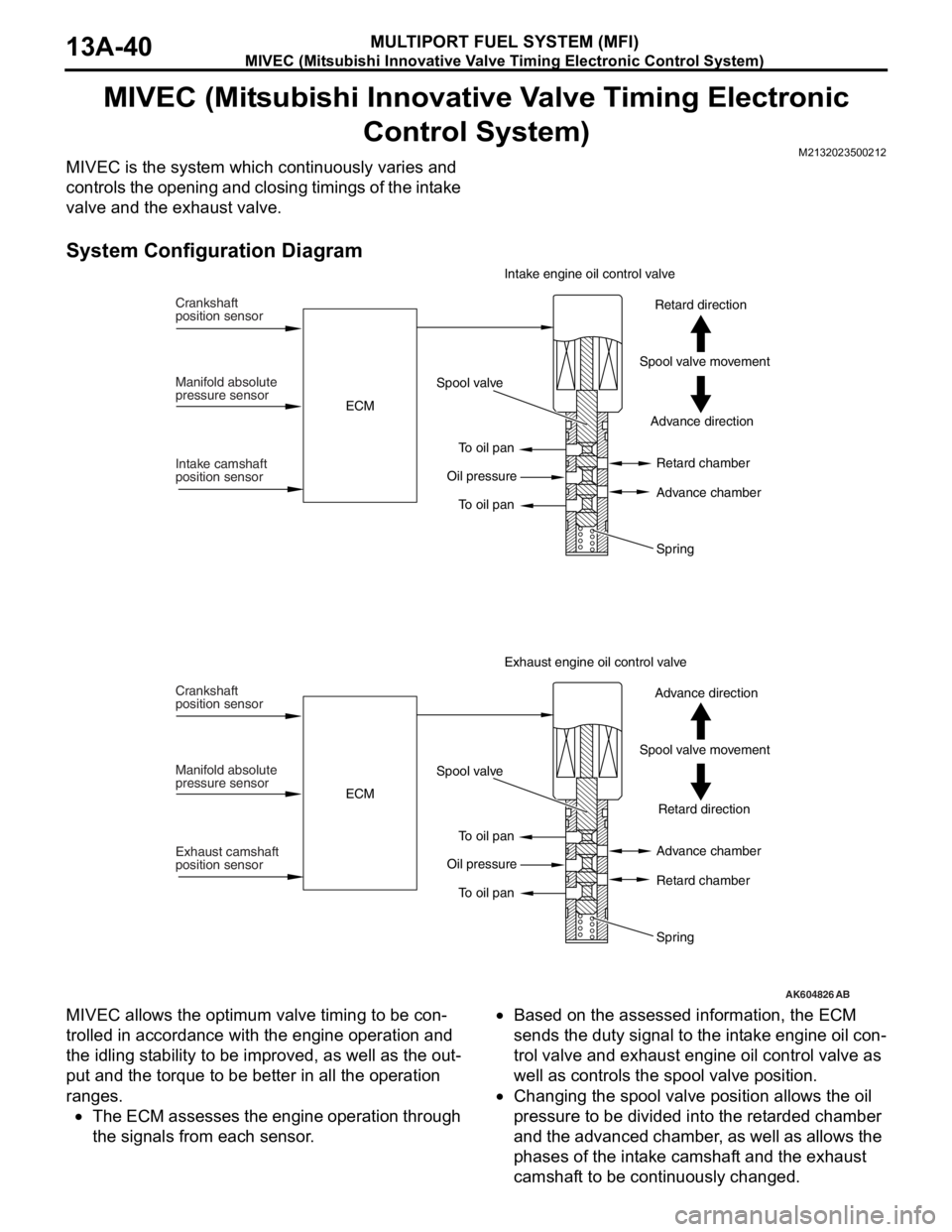
MIVEC is the system which continuously varies and
controls the opening and closing timings of the intake
valve and the exhaust valve.
System Configuration Diagram
MIVEC allows the optimum valve timing to be con-
trolled in accordance with the engine operation and
the idling stability to be improved, as well as the out
-
put and the torque to be better in all the operation
ranges.
•The ECM assesses the engine operation through
the signals from each sensor.
•Based on the assessed information, the ECM
sends the duty signal to the intake engine oil con
-
trol valve and exhaust engine oil control valve as
well as controls the spool valve position.
•Changing the spool valve position allows the oil
pressure to be divided into the retarded chamber
and the advanced chamber, as well as allows the
phases of the intake camshaft and the exhaust
camshaft to be continuously changed.
AK604826AB
Crankshaft
position sensor
Manifold absolute
pressure sensor
Intake camshaft
position sensorECMSpool valve
To oil pan
To oil pan Oil pressureAdvance direction Spool valve movementRetard direction Intake engine oil control valve
Retard chamber
Advance chamber
Spring
Crankshaft
position sensor
Manifold absolute
pressure sensor
Exhaust camshaft
position sensorECMSpool valve
To oil pan
To oil pan Oil pressureRetard direction Spool valve movementAdvance direction Exhaust engine oil control valve
Advance chamber
Retard chamber
Spring
Page 134 of 241
MIVEC (Mitsubishi Innovative Valve Timing Electronic Control System)
MULTIPORT FUEL SYSTEM (MFI)13A-41
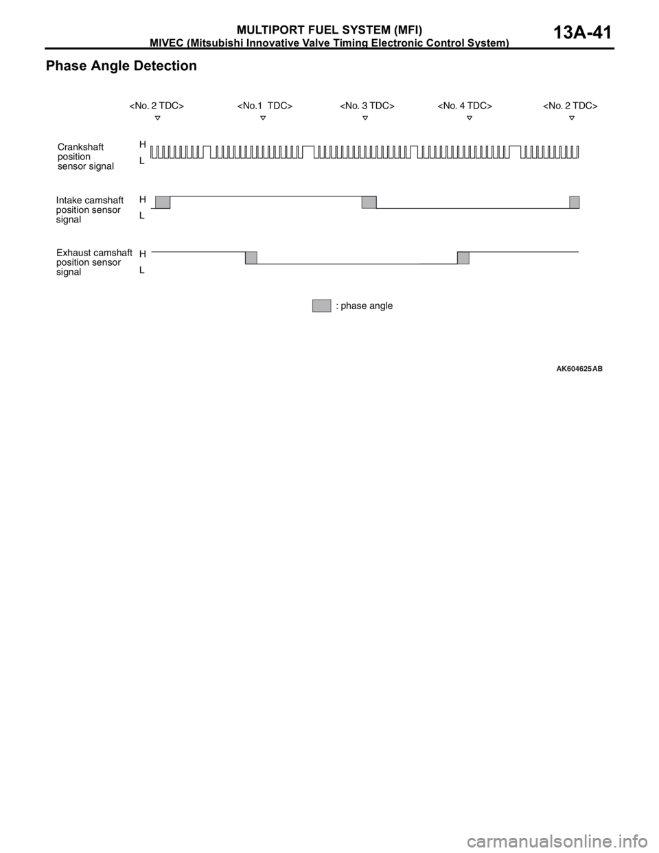
Phase Angle Detection
AK604625
H
L H
L
H
L
AB
Crankshaft
position
sensor signal
Intake camshaft
position sensor
signal
Exhaust camshaft
position sensor
signal
: phase angle
Page 135 of 241
MIVEC (Mitsubishi Innovative Valve Timing Electronic Control System)
MULTIPORT FUEL SYSTEM (MFI)13A-42
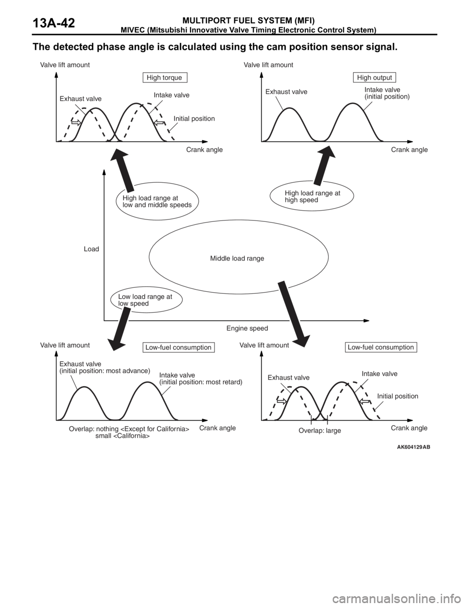
The detected phase angle is calculated using the cam position sensor signal.
AK604129AB
Overlap: nothing
small
(initial position)
Exhaust valve
(initial position: most advance)
Intake valve
(initial position: most retard)Exhaust valveIntake valve
Initial position
Overlap: large Initial position
Crank angle Crank angle
Crank angle Crank angle Valve lift amount Valve lift amountValve lift amount Valve lift amount
LoadHigh output High torque
Middle load range
Low load range at
low speedHigh load range at
low and middle speedsHigh load range at
high speed
Engine speed
Low-fuel consumptionLow-fuel consumption
Page 138 of 241
MULTIPORT FUEL INJECTION (MFI) RELAY CONTROL
MULTIPORT FUEL SYSTEM (MFI)13A-45
MULTIPORT FUEL INJECTION (MFI) RELAY CONTROLM2132006000173
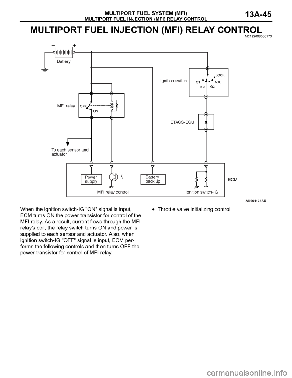
When the ignition switch-IG "ON" signal is input,
ECM turns ON the power transistor for control of the
MFI relay. As a result, current flows through the MFI
relay's coil, the relay switch turns ON and power is
supplied to each sensor and actuator. Also, when
ignition switch-IG "OFF" signal is input, ECM per
-
forms the following controls and then turns OFF the
power transistor for control of MFI relay.
•Throttle valve initializing control
AK604134AB OFF
ON
IG2 STLOCK
ACC
IG1
MFI relay
Power
supply
MFI relay control Ignition switch-IGBattery
back up To each sensor and
actuatorIgnition switch
ETACS-ECU Battery
ECM
Page 139 of 241
FUEL PUMP RELAY CONTROL
MULTIPORT FUEL SYSTEM (MFI)13A-46
FUEL PUMP RELAY CONTROLM2132006500208
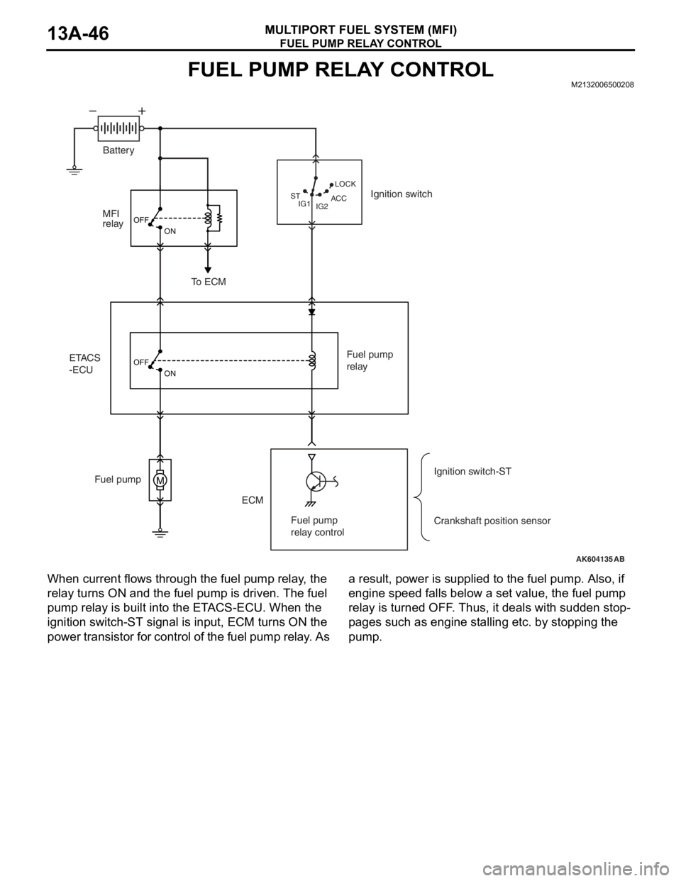
When current flows through the fuel pump relay, the
relay turns ON and the fuel pump is driven. The fuel
pump relay is built into the ETACS-ECU. When the
ignition switch-ST signal is input, ECM turns ON the
power transistor for control of the fuel pump relay. As a result, power is supplied to the fuel pump. Also, if
engine speed falls below a set value, the fuel pump
relay is turned OFF. Thus, it deals with sudden stop
-
pages such as engine stalling etc. by stopping the
pump.
AK604135
M
OFF
ON
OFF
ON
AB IG2 STLOCK
ACC
IG1
ETACS
-ECUMFI
relay
ECM Fuel pumpFuel pump
relay
Crankshaft position sensor Ignition switch
To ECM
Ignition switch-ST Battery
Fuel pump
relay control
Page 142 of 241
HEATED OXYGEN SENSOR HEATER CONTROL
MULTIPORT FUEL SYSTEM (MFI)13A-49
HEATED OXYGEN SENSOR HEATER CONTROLM2132007000206
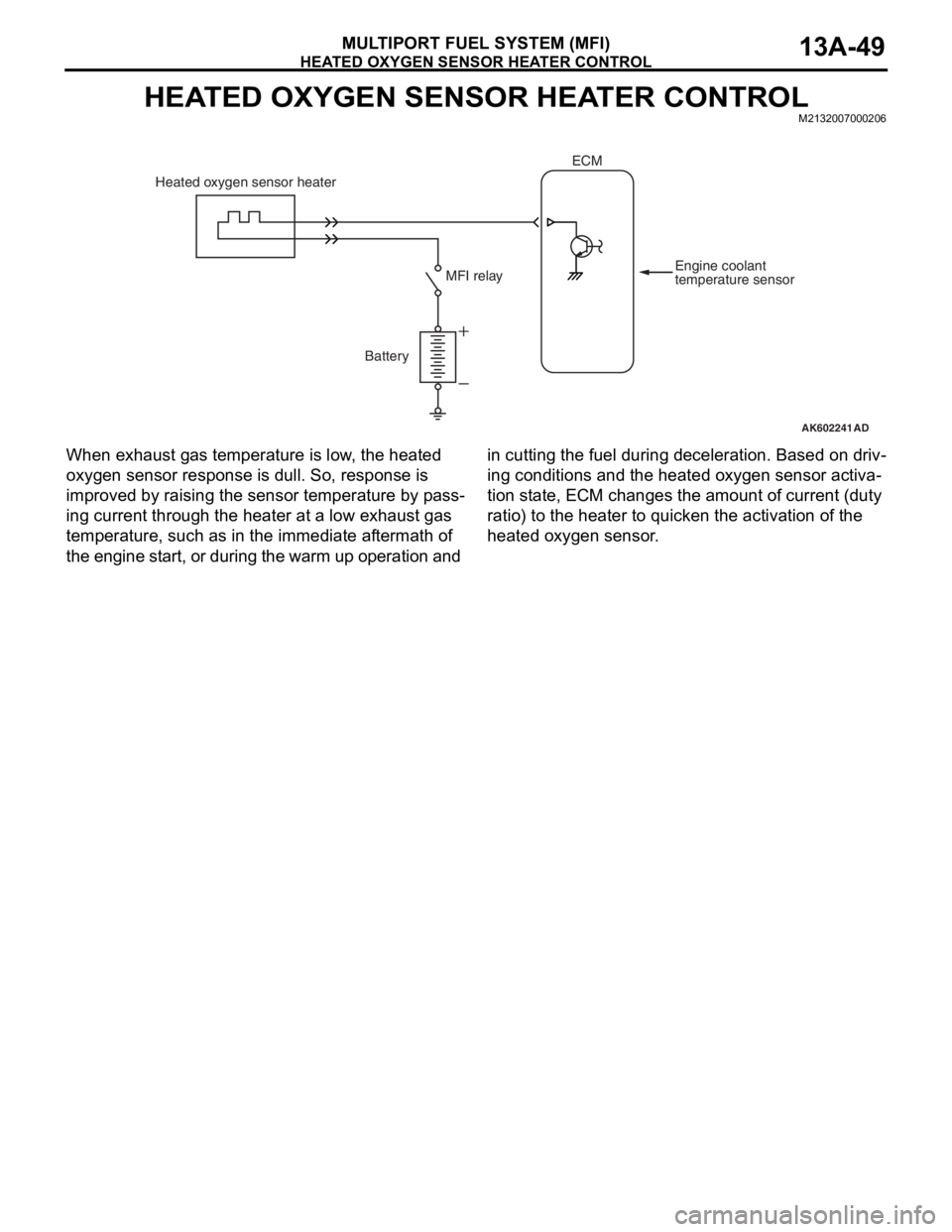
When exhaust gas temperature is low, the heated
oxygen sensor response is dull. So, response is
improved by raising the sensor temperature by pass
-
ing current through the heater at a low exhaust gas
temperature, such as in the immediate aftermath of
the engine start, or during the warm up operation and in cutting the fuel during deceleration. Based on driv
-
ing conditions and the heated oxygen sensor activa-
tion state, ECM changes the amount of current (duty
ratio) to the heater to quicken the activation of the
heated oxygen sensor.
AK602241AD
Battery Heated oxygen sensor heater
Engine coolant
temperature sensor MFI relay
ECM
Page 144 of 241
GENERATOR CONTROL
MULTIPORT FUEL SYSTEM (MFI)13A-51
GENERATOR CONTROLM2132025000172
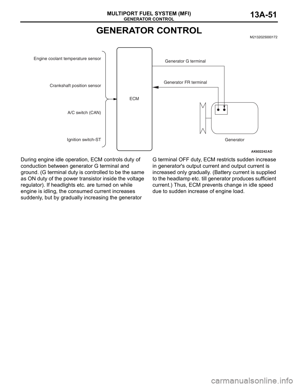
During engine idle operation, ECM controls duty of
conduction between generator G terminal and
ground. (G terminal duty is controlled to be the same
as ON duty of the power transistor inside the voltage
regulator). If headlights etc. are turned on while
engine is idling, the consumed current increases
suddenly, but by gradually increasing the generator G terminal OFF duty, ECM restricts sudden increase
in generator's output current and output current is
increased only gradually. (Battery current is supplied
to the headlamp etc. till generator produces sufficient
current.) Thus, ECM prevents change in idle speed
due to sudden increase of engine load.
AK602242 AD
Engine coolant temperature sensor
Generator G terminal
Generator FR terminal
Generator Crankshaft position sensor
A/C switch (CAN)
Ignition switch-STECM
Page 145 of 241
EVAPORATIVE EMISSION CONTROL SYSTEM INCORRECT PURGE FLOW MONITOR
MULTIPORT FUEL SYSTEM (MFI)13A-52
EVAPORATIVE EMISSION CONTROL SYSTEM INCORRECT
PURGE FLOW MONITOR
M2132027200019
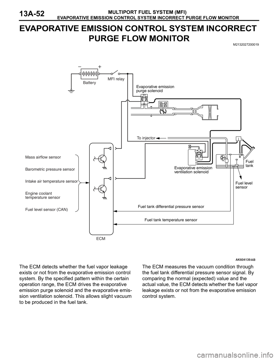
The ECM detects whether the fuel vapor leakage
exists or not from the evaporative emission control
system. By the specified pattern within the certain
operation range, the ECM drives the evaporative
emission purge solenoid and the evaporative emis
-
sion ventilation solenoid. This allows slight vacuum
to be produced in the fuel tank.
The ECM measures the vacuum condition through
the fuel tank differential pressure sensor signal. By
comparing the normal (expected) value and the
actual value, the ECM detects whether the fuel vapor
leakage exists or not from the evaporative emission
control system.
AK604139
Evaporative emission
purge solenoid
Evaporative emission
ventilation solenoid
Fuel tank differential pressure sensor
Fuel tank temperature sensor
AB
BatteryMFI relay
ECM Mass airflow sensor
Barometric pressure sensor
Intake air temperature sensor
Engine coolant
temperature sensor
Fuel level sensor (CAN)Fuel
tank
Fuel level
sensor To injector
Page 162 of 241
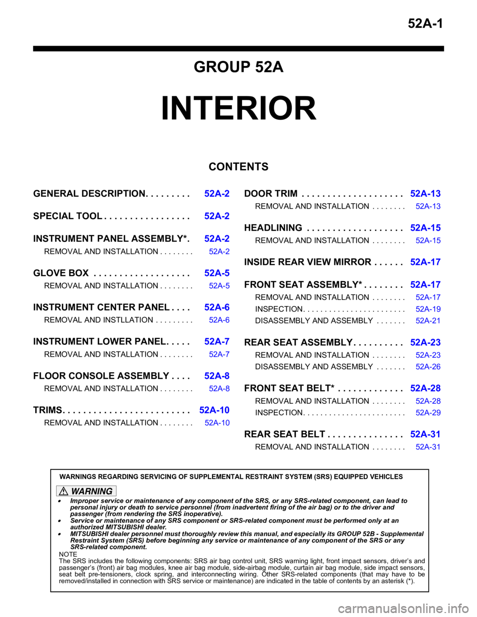
52A-1
GROUP 52A
INTERIOR
CONTENTS
GENERAL DESCRIPTION. . . . . . . . .52A-2
SPECIAL TOOL . . . . . . . . . . . . . . . . .52A-2
INSTRUMENT PANEL ASSEMBLY*.52A-2
REMOVAL AND INSTALLATION . . . . . . . . 52A-2
GLOVE BOX . . . . . . . . . . . . . . . . . . .52A-5
REMOVAL AND INSTALLATION . . . . . . . . 52A-5
INSTRUMENT CENTER PANEL . . . .52A-6
REMOVAL AND INSTLLATION . . . . . . . . . 52A-6
INSTRUMENT LOWER PANEL. . . . .52A-7
REMOVAL AND INSTALLATION . . . . . . . . 52A-7
FLOOR CONSOLE ASSEMBLY . . . .52A-8
REMOVAL AND INSTALLATION . . . . . . . . 52A-8
TRIMS. . . . . . . . . . . . . . . . . . . . . . . . .52A-10
REMOVAL AND INSTALLATION . . . . . . . . 52A-10
DOOR TRIM . . . . . . . . . . . . . . . . . . . .52A-13
REMOVAL AND INSTALLATION . . . . . . . . 52A-13
HEADLINING . . . . . . . . . . . . . . . . . . .52A-15
REMOVAL AND INSTALLATION . . . . . . . . 52A-15
INSIDE REAR VIEW MIRROR . . . . . .52A-17
FRONT SEAT ASSEMBLY* . . . . . . . .52A-17
REMOVAL AND INSTALLATION . . . . . . . . 52A-17
INSPECTION. . . . . . . . . . . . . . . . . . . . . . . . 52A-19
DISASSEMBLY AND ASSEMBLY . . . . . . . 52A-21
REAR SEAT ASSEMBLY . . . . . . . . . .52A-23
REMOVAL AND INSTALLATION . . . . . . . . 52A-23
DISASSEMBLY AND ASSEMBLY . . . . . . . 52A-26
FRONT SEAT BELT* . . . . . . . . . . . . .52A-28
REMOVAL AND INSTALLATION . . . . . . . . 52A-28
INSPECTION. . . . . . . . . . . . . . . . . . . . . . . . 52A-29
REAR SEAT BELT . . . . . . . . . . . . . . .52A-31
REMOVAL AND INSTALLATION . . . . . . . . 52A-31
WARNINGS REGARDING SERVICING OF SUPPLEMENTAL RESTRAINT SYSTEM (SRS) EQUIPPED VEHICLES
WARNING
•Improper service or maintenance of an y component of the SRS, or any SRS-related component, can lead to
personal injury or death to service personnel (from inadvertent firing of the air bag) or to the driver and
passenger (from renderin g the SRS inoperative).
•Service or maintenance of any SRS component or SRS-related component must be performed only at an
authorized MITSUBISHI dealer.
•MITSUBISHI dealer personnel must thoroughly review this manual, and especially its GROUP 52B - Supplemental
Restraint System (SRS) before beginning any service or maintenance of any component of the SRS or any
SRS-related component.
NOTE
The SRS includes the following components: SRS air bag control unit, SRS warning light, front impact sensors, driver’s and
passenger’s (front) air bag modules, knee air bag module, side-airbag module, curtain air bag module, side impact sensors,
seat belt pre-tensioners, clock spring, and interconnecting wiring. Other SRS-related components (that may have to be
removed/installed in connection with SRS service or maintenance) are indicated in the table of contents by an asterisk (*).