ESP MITSUBISHI LANCER EVOLUTION X 2008 Workshop Manual
[x] Cancel search | Manufacturer: MITSUBISHI, Model Year: 2008, Model line: LANCER EVOLUTION X, Model: MITSUBISHI LANCER EVOLUTION X 2008Pages: 241, PDF Size: 8.26 MB
Page 7 of 241
ANTENNA
CHASSIS ELECTRICAL54A-26
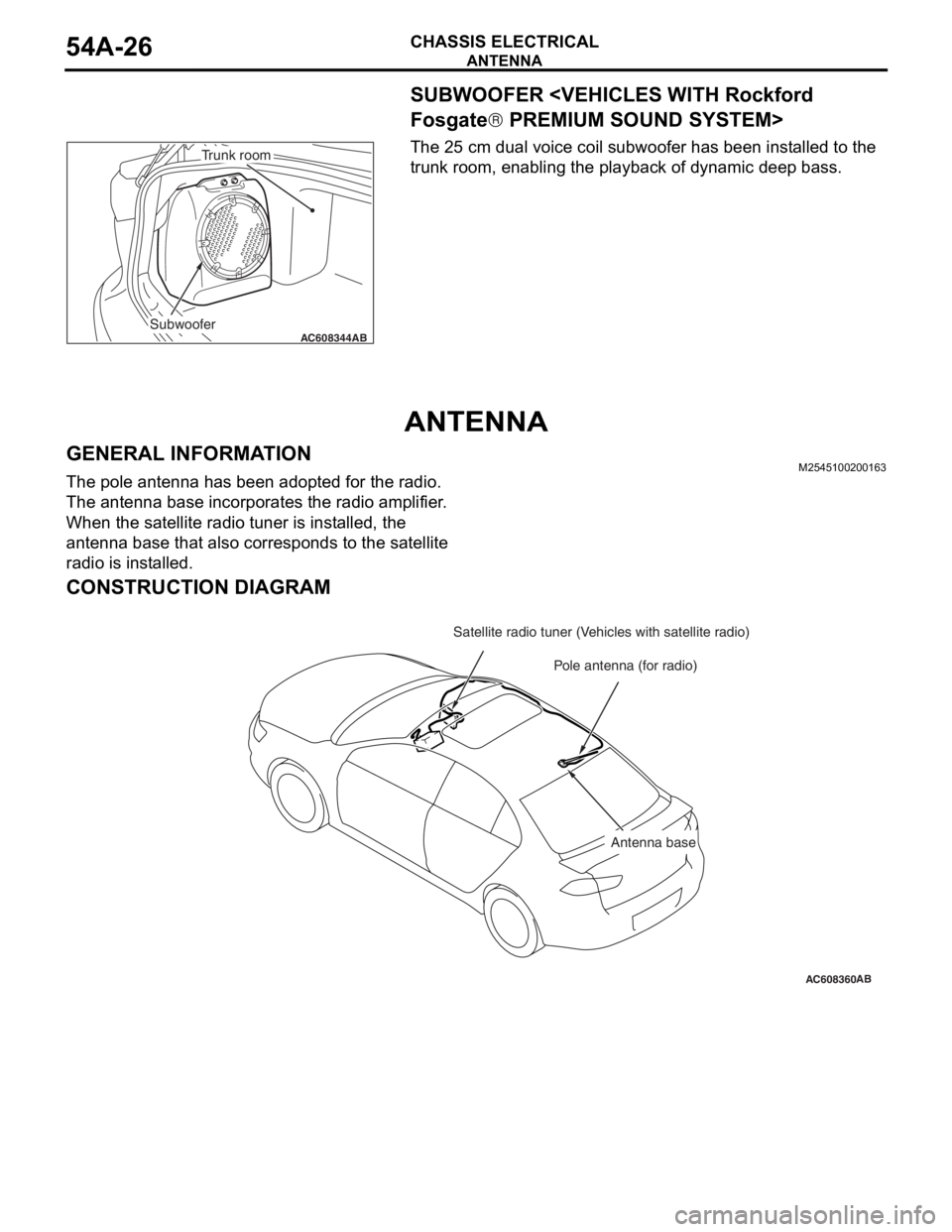
SUBWOOFER
® PREMIUM SOUND SYSTEM>
The 25 cm dual voice coil subwoofer has been installed to the
trunk room, enabling the playback of dynamic deep bass.
ANTENNA
GENERAL INFORMATIONM2545100200163
The pole antenna has been adopted for the radio.
The antenna base incorporates the radio amplifier.
When the satellite radio tuner is installed, the
antenna base that also corresponds to the satellite
radio is installed.
CONSTRUCTION DIAGRAM
AC608344ABSubwoofer
Trunk room
AC608360
Pole antenna (for radio)
AB
Satellite radio tuner (Vehicles with satellite radio)
Antenna base
Page 9 of 241
MITSUBISHI MULTI COMMUNICATION SYSTEM (MMCS)
CHASSIS ELECTRICAL54A-28
Navigation function
The storage of very large map data is now possible,
and the following contents have been adopted.
•Map type navigation
•NAVTEQ map database
•Map data stored in hard disc drive
•U.S. English, French, and Spanish are available
to select.
Audio and visual function
The following functions are in addition to the naviga-
tion function:
•Music server function
•DVD drive unit
•FM/AM radio
•MP3/WMA playback function
•Control by steering wheel audio remote comtrol
switch
•Integrated 4-ch power amplifier (MAX: 180 W)
•Correspond to Rockford Fosgate® premium
sound system
•Output of DVD video 5.1 channel data
•Connect with satellite radio tuner
Other function
The following functions are in addition to the naviga-
tion, audio and visual function:
•Clock display
•Connect with hands free unit
•A/C information display
•Outside temperature display
•Trip information display (Average fuel consump-
tion etc.)
•Function customize
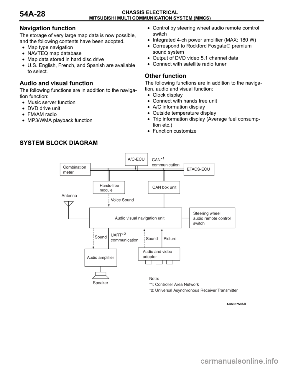
SYSTEM BLOCK DIAGRAM
AC505476
AC608750 ZC3050180000
Audio and video
adopter Antenna
Steering wheel
audio remote control
switch
Speaker
*1: Controller Area Network Note:
*2: Universal Asynchronous Receiver Transmitter UART
communicationn
Sound Sound Voice Sound
Picture
Audio amplifierCAN box unitETACS-ECU Combination
meter
Audio visual navigation unitA/C-ECU
Hands-free
module
CAN
communication
AB
Page 34 of 241
GENERAL DESCRIPTION
HEATER, AIR CONDITIONING AND VENTILATION55-2
GENERAL DESCRIPTIONM2551001500040
The blower, heater, and evaporator have been inte-
grated with the heater and A/C system to achieve a
greater fan power and noise reduction.
FEATURES
.
ENHANCEMENTS IN COMFORT
•With the adoption of fully-automatic A/C, the out-
side/inside air circulation switching, air outlet, and
outlet air temperature are automatically con
-
trolled according to the ambient temperature,
solar radiation, and passenger compartment tem
-
perature so that the optimum air conditioner is
achieved.
•By the adoption of clean air filter, the air quality
inside the passenger compartment has been
enhanced.
.
ENHANCEMENTS IN OPERATION
PERFORMANCE
•Operability has been enhanced by the adoption
of large triple dial.
•Customise function has been added for the
enhanced convenience.
.
ENHANCEMENTS IN FUEL ECONOMY
•The high efficiency compressor with a 2-step pro-
file oil separator has been installed, thus enhanc-
ing the fuel economy.
•The idle-up speed is controlled in two steps to
secure the air cooling performance during sum
-
mer and to enhance the fuel economy in the sea-
sons with moderate temperature.
•Enhancement of fuel economy by the cooling fan
control depending on the refrigerant pressure and
vehicle speed.
.
ENHANCEMENT IN SAFETY
•A/C system is stopped when the air bags are
deployed.
•Crushable space has been adopted to heater unit
to reduce the risk of passenger injuries in case of
a collision.
.
GLOBAL ENVIRONMENT PROTECTION
•New refrigerant system (HFC134a) has been
adopted.
•By the optimisation of A/C system, the refrigerant
charging amount has been reduced.
•Clean air filter media and its cover are separated
to reduce waste materials.
.
ENHANCEMENTS IN SERVICE QUALITY
•Reduction of refrigerant gas leakage and
enhancement in serviceability by incorporating
condenser and receiver
•Clean air filter is installed to the backside of glove
box to facilitate the filter replacement.
.
ENHANCEMENTS IN RESPONSIBILITY
Reliable information transmission is achieved by
connecting A/C-ECU and each ECU via CAN com
-
munication.
SPECIFICATIONS
ITEMSPECIFICATION
Air conditioning switch typeRotary type
Compressor typeMSC90CAS
Cooling output5.5 kw
Heating output5.7 kw
RefrigerantTy p eR134a (HFC-134a)
Charge quantity g (oz.)480 - 520 (16.9 - 18.3)
Page 47 of 241
BASE ENGINE
ENGINE MECHANICAL11A-3
BASE ENGINEM2112001001050
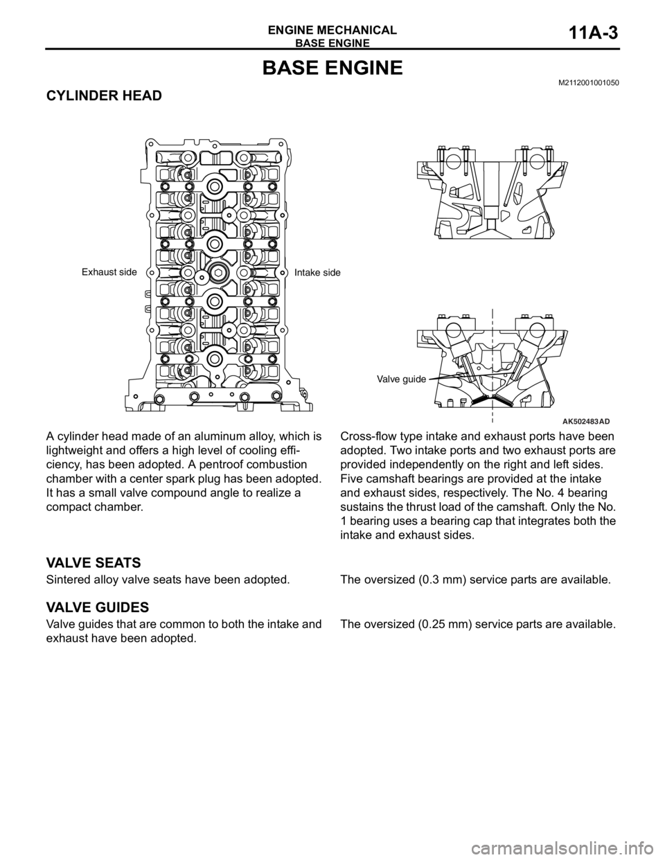
CYLINDER HEAD
A cylinder head made of an aluminum alloy, which is
lightweight and offers a high level of cooling effi
-
ciency, has been adopted. A pentroof combustion
chamber with a center spark plug has been adopted.
It has a small valve compound angle to realize a
compact chamber.
Cross-flow type intake and exhaust ports have been
adopted. Two intake ports and two exhaust ports are
provided independently on the right and left sides.
Five camshaft bearings are provided at the intake
and exhaust sides, respectively. The No. 4 bearing
sustains the thrust load of the camshaft. Only the No.
1 bearing uses a bearing cap that integrates both the
intake and exhaust sides.
VA LV E S E AT S
Sintered alloy valve seats have been adopted.The oversized (0.3 mm) service parts are available.
VA LV E G U I D E S
Valve guides that are common to both the intake and
exhaust have been adopted.The oversized (0.25 mm) service parts are available.
AK502483
Valve guide
AD
Exhaust side
Intake side
Page 66 of 241

AUTO-CRUISE CONTROL SYSTEM
ENGINE AND EMISSION CONTROL17-4
COMPONENTS AND FUNCTIONS
ComponentFunction
Accelerator pedal position sensor (APP sensor)Informs the ECM of the accelerator pedal
depression.
Auto-cruise control switch"ON/OFF" switchPower switch for auto-cruise control system.
"ACC/RES" switchVehicle speed is set with the "ACC/RES" switch and
"COAST/SET" switch.
"COAST/SET" switch
"CANCEL" switchCancels the cruise speed setting.
Cancel systemClutch switch
the clutch operation, the clutch pedal status is
detected.
Stoplight switch•Because the constant speed driving is canceled
by the brake operation, it detects the brake pedal
status.
•As for the stoplight switch, two built-in switches,
the stoplight switch which is also used for the
stoplight illumination and the brake switch which
is used exclusively for the auto-cruise control, are
integrated, and thus the reliability is enhanced.
Transmission range
switch
the selector lever operation, it detects the "N"
position.
"CRUISE" indicator lightThe light is included in the combination meter and
illuminates when the "ON/OFF" switch is pressed
(auto-cruise control system: ON).
Data link connectorIf the M.U.T.-III scan tool is connected, the input
check code from the ECM can be read.
Engine control module (ECM)•Based on the input signal from each sensor and
switch, it outputs the throttle opening instruction
signal to the TAC motor.
•Based on the input signal from each sensor and
switch, it outputs the transaxle control signal to
the TCM
•Based on the vehicle speed signal from the
vehicle speed sensor, it calculates the vehicle
speed
•Based on the secondary pulley speed sensor
signal from the TCM, it calculates the vehicle
speed
•Based on the selector lever "N" position signal of
the transmission range switch from the ECM, it
cancels constant speed driving.
•Outputs the ON/OFF signals of "CRUISE"
indicator light and auto-cruise control system.
•The diagnostic trouble code signal is sent to the
"CRUISE" indicator light.
•The input check code is sent to the data link
connector.
Throttle actuator control motor (TAC motor)The throttle valve opens and closes in response to
the throttle angle signal from the ECM.
Page 117 of 241
ACTUATOR
MULTIPORT FUEL SYSTEM (MFI)13A-24
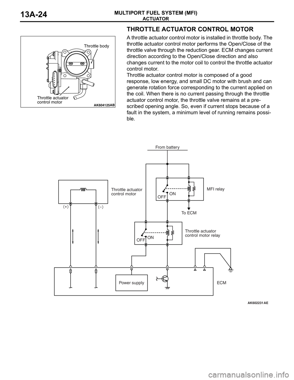
THROTTLE ACTUATOR CONTROL MOTOR
A throttle actuator control motor is installed in throttle body. The
throttle actuator control motor performs the Open/Close of the
throttle valve through the reduction gear. ECM changes current
direction according to the Open/Close direction and also
changes current to the motor coil to control the throttle actuator
control motor.
Throttle actuator control motor is composed of a good
response, low energy, and small DC motor with brush and can
generate rotation force corresponding to the current applied on
the coil. When there is no current passing through the throttle
actuator control motor, the throttle valve remains at a pre
-
scribed opening angle. So, even if current stops because of a
fault in the system, a minimum level of running remains possi
-
ble.
AK604125AB
Throttle body
Throttle actuator
control motor
AK602231
Throttle actuator
control motor
Throttle actuator
control motor relayMFI relay
To ECM
Power supplyOFFON
OFF
ON
AE
From battery
ECM
Page 142 of 241
HEATED OXYGEN SENSOR HEATER CONTROL
MULTIPORT FUEL SYSTEM (MFI)13A-49
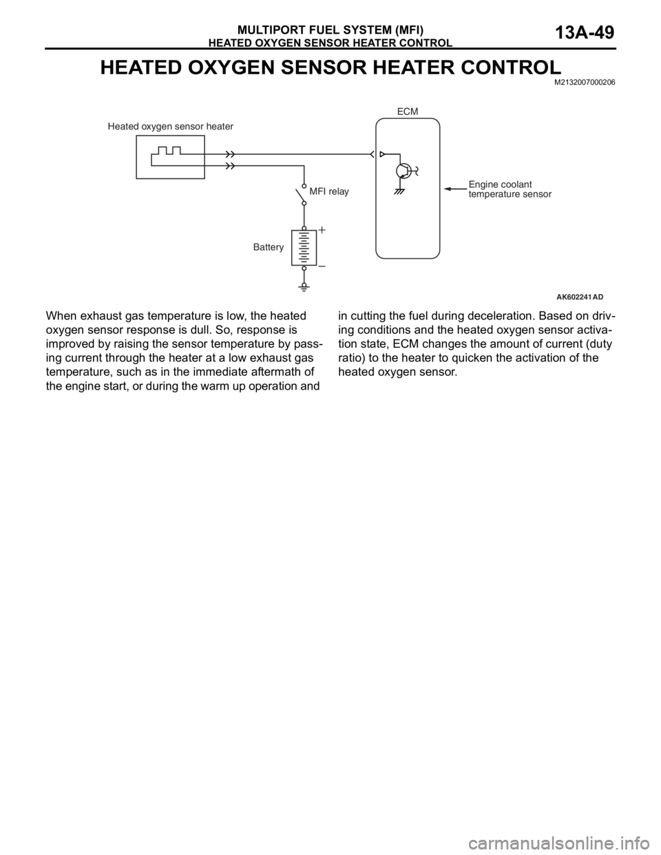
HEATED OXYGEN SENSOR HEATER CONTROLM2132007000206
When exhaust gas temperature is low, the heated
oxygen sensor response is dull. So, response is
improved by raising the sensor temperature by pass
-
ing current through the heater at a low exhaust gas
temperature, such as in the immediate aftermath of
the engine start, or during the warm up operation and in cutting the fuel during deceleration. Based on driv
-
ing conditions and the heated oxygen sensor activa-
tion state, ECM changes the amount of current (duty
ratio) to the heater to quicken the activation of the
heated oxygen sensor.
AK602241AD
Battery Heated oxygen sensor heater
Engine coolant
temperature sensor MFI relay
ECM
Page 162 of 241
52A-1
GROUP 52A
INTERIOR
CONTENTS
GENERAL DESCRIPTION. . . . . . . . .52A-2
SPECIAL TOOL . . . . . . . . . . . . . . . . .52A-2
INSTRUMENT PANEL ASSEMBLY*.52A-2
REMOVAL AND INSTALLATION . . . . . . . . 52A-2
GLOVE BOX . . . . . . . . . . . . . . . . . . .52A-5
REMOVAL AND INSTALLATION . . . . . . . . 52A-5
INSTRUMENT CENTER PANEL . . . .52A-6
REMOVAL AND INSTLLATION . . . . . . . . . 52A-6
INSTRUMENT LOWER PANEL. . . . .52A-7
REMOVAL AND INSTALLATION . . . . . . . . 52A-7
FLOOR CONSOLE ASSEMBLY . . . .52A-8
REMOVAL AND INSTALLATION . . . . . . . . 52A-8
TRIMS. . . . . . . . . . . . . . . . . . . . . . . . .52A-10
REMOVAL AND INSTALLATION . . . . . . . . 52A-10
DOOR TRIM . . . . . . . . . . . . . . . . . . . .52A-13
REMOVAL AND INSTALLATION . . . . . . . . 52A-13
HEADLINING . . . . . . . . . . . . . . . . . . .52A-15
REMOVAL AND INSTALLATION . . . . . . . . 52A-15
INSIDE REAR VIEW MIRROR . . . . . .52A-17
FRONT SEAT ASSEMBLY* . . . . . . . .52A-17
REMOVAL AND INSTALLATION . . . . . . . . 52A-17
INSPECTION. . . . . . . . . . . . . . . . . . . . . . . . 52A-19
DISASSEMBLY AND ASSEMBLY . . . . . . . 52A-21
REAR SEAT ASSEMBLY . . . . . . . . . .52A-23
REMOVAL AND INSTALLATION . . . . . . . . 52A-23
DISASSEMBLY AND ASSEMBLY . . . . . . . 52A-26
FRONT SEAT BELT* . . . . . . . . . . . . .52A-28
REMOVAL AND INSTALLATION . . . . . . . . 52A-28
INSPECTION. . . . . . . . . . . . . . . . . . . . . . . . 52A-29
REAR SEAT BELT . . . . . . . . . . . . . . .52A-31
REMOVAL AND INSTALLATION . . . . . . . . 52A-31
WARNINGS REGARDING SERVICING OF SUPPLEMENTAL RESTRAINT SYSTEM (SRS) EQUIPPED VEHICLES
WARNING
•Improper service or maintenance of an y component of the SRS, or any SRS-related component, can lead to
personal injury or death to service personnel (from inadvertent firing of the air bag) or to the driver and
passenger (from renderin g the SRS inoperative).
•Service or maintenance of any SRS component or SRS-related component must be performed only at an
authorized MITSUBISHI dealer.
•MITSUBISHI dealer personnel must thoroughly review this manual, and especially its GROUP 52B - Supplemental
Restraint System (SRS) before beginning any service or maintenance of any component of the SRS or any
SRS-related component.
NOTE
The SRS includes the following components: SRS air bag control unit, SRS warning light, front impact sensors, driver’s and
passenger’s (front) air bag modules, knee air bag module, side-airbag module, curtain air bag module, side impact sensors,
seat belt pre-tensioners, clock spring, and interconnecting wiring. Other SRS-related components (that may have to be
removed/installed in connection with SRS service or maintenance) are indicated in the table of contents by an asterisk (*).