Motor MITSUBISHI LANCER EVOLUTION X 2008 Workshop Manual
[x] Cancel search | Manufacturer: MITSUBISHI, Model Year: 2008, Model line: LANCER EVOLUTION X, Model: MITSUBISHI LANCER EVOLUTION X 2008Pages: 241, PDF Size: 8.26 MB
Page 36 of 241
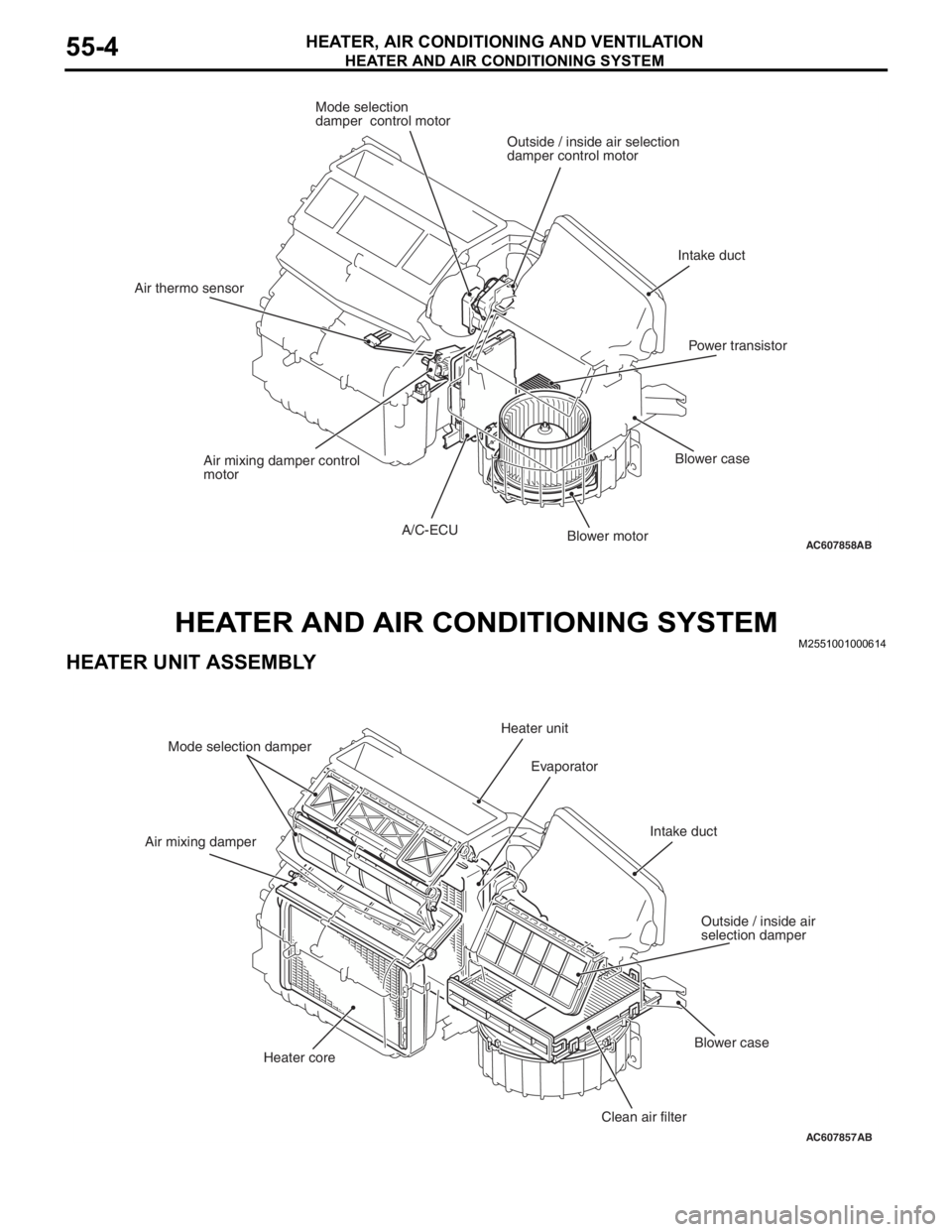
HEATER AND AIR CONDITIONING SYSTEM
HEATER, AIR CONDITIONING AND VENTILATION55-4
HEATER AND AIR CONDITIONING SYSTEMM2551001000614
HEATER UNIT ASSEMBLY
AC607858Blower motor Outside / inside air selection
damper control motor
Air mixing damper control
motor Air thermo sensorAB
Mode selection
damper control motor
A/C-ECUPower transistor Intake duct
Blower case
AC607857
Heater unit
Air mixing damper
Heater coreEvaporator Mode selection damper
Outside / inside air
selection damper
AB
Intake duct
Blower case
Clean air filter
Page 37 of 241
HEATER AND AIR CONDITIONING SYSTEM
HEATER, AIR CONDITIONING AND VENTILATION55-5
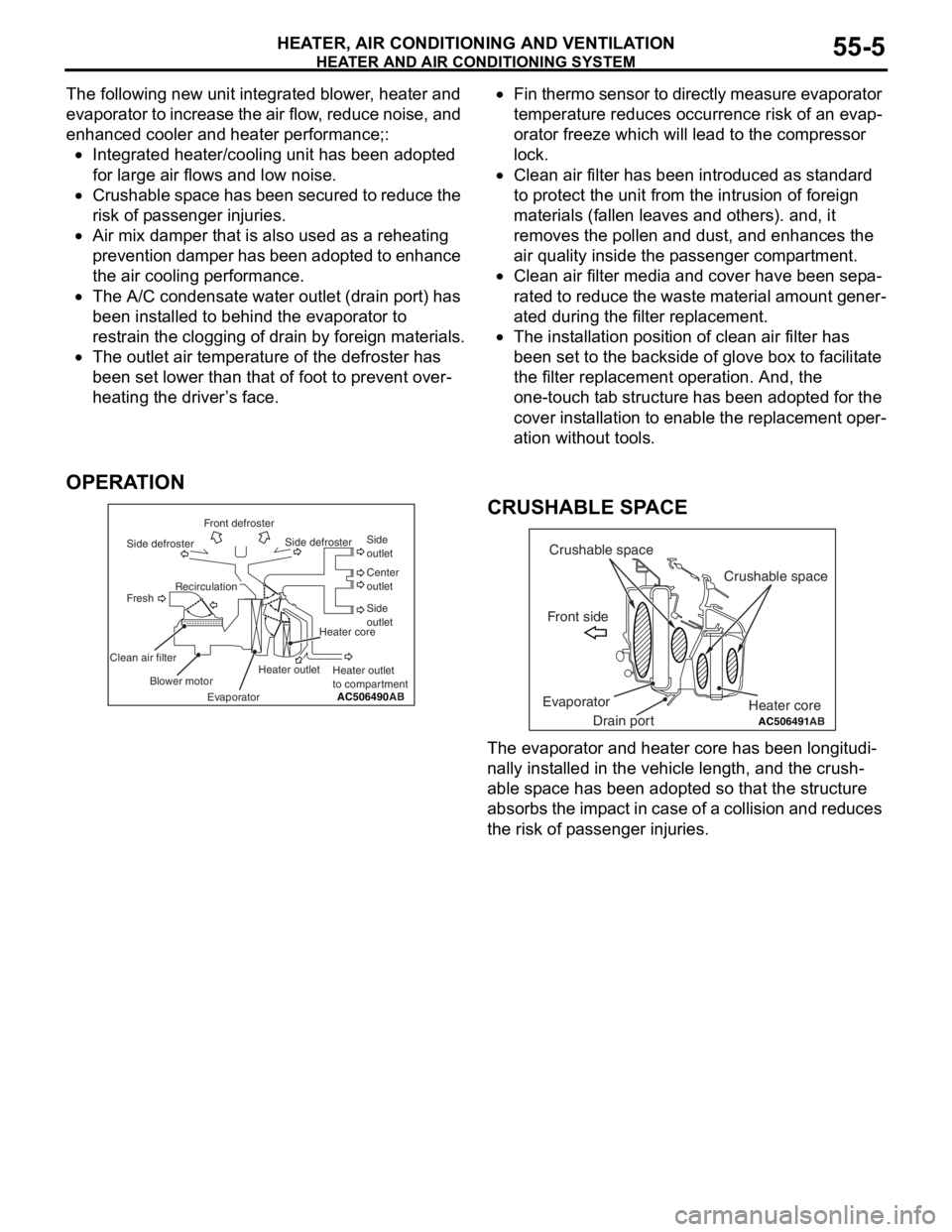
The following new unit integrated blower, heater and
evaporator to increase the air flow, reduce noise, and
enhanced cooler and heater performance;:
•Integrated heater/cooling unit has been adopted
for large air flows and low noise.
•Crushable space has been secured to reduce the
risk of passenger injuries.
•Air mix damper that is also used as a reheating
prevention damper has been adopted to enhance
the air cooling performance.
•The A/C condensate water outlet (drain port) has
been installed to behind the evaporator to
restrain the clogging of drain by foreign materials.
•The outlet air temperature of the defroster has
been set lower than that of foot to prevent over
-
heating the driver’s face.
•Fin thermo sensor to directly measure evaporator
temperature reduces occurrence risk of an evap
-
orator freeze which will lead to the compressor
lock.
•Clean air filter has been introduced as standard
to protect the unit from the intrusion of foreign
materials (fallen leaves and others). and, it
removes the pollen and dust, and enhances the
air quality inside the passenger compartment.
•Clean air filter media and cover have been sepa-
rated to reduce the waste material amount gener-
ated during the filter replacement.
•The installation position of clean air filter has
been set to the backside of glove box to facilitate
the filter replacement operation. And, the
one-touch tab structure has been adopted for the
cover installation to enable the replacement oper
-
ation without tools.
OPERATION
.
CRUSHABLE SPACE
The evaporator and heater core has been longitudi-
nally installed in the vehicle length, and the crush-
able space has been adopted so that the structure
absorbs the impact in case of a collision and reduces
the risk of passenger injuries.
AC506490AB Front defroster
Side defrosterSide defrosterSide
outlet
Side
outlet Center
outlet
Heater core
Heater outlet
to compartment Recirculation
Fresh
Clean air filter
Blower motor
EvaporatorHeater outlet
AC506491
Crushable space
Crushable space
Front side
Drain port EvaporatorHeater coreAB
Page 46 of 241

GENERAL DESCRIPTION
ENGINE MECHANICAL11A-2
GENERAL DESCRIPTIONM2112000101162
This model is equipped with a newly developed 4B11
engine. It is a 4-cylinder, double overhead camshaft
(DOHC) engine with a 2.0-L cylinder displacement.
This engine has adopted the following features:
•MIVEC (MITSUBISHI INNOVATIVE VALVE TIM-
ING ELECTRONIC CONTROL SYSTEM) for
both the intake and exhaust valves
•Cylinder block made of an aluminum alloy
•Valve train with direct-acting valve tappets
•Silent timing chain
MAIN SPECIFICATIONS
DescriptionsSpecifications
Engine type4B11
Bore × stroke mm (in)86 (3.4) × 86 (3.4)
Total displacement cm3 (cu in)1,998 (121.9)
Combustion chamberPent-roof type
Number of cylinders4
Valve mechanismTy p eDOHC
Intake valve8
Exhaust valve8
Compression ratio10.0
Va l v e t i m i n gIntake valveOpens (BTDC)3° − 28°
0° − 25°
Closes (ABDC)45° − 20°
48° − 23°
Exhaust valveOpens (BBDC)41° − 21°
44° − 24°
Closes (ATDC)3° − 23°
0° − 20°
Maximum output kW/r/min (HP/r/min)107/6,000 (143/6,000)
113/6,000 (152/6,000)
Maximum torque N⋅m/r/min (lbs-ft/r/min)194/4,250 (143/4,250)
198/4,250 (146/4,250)
Fuel injection system typeElectronic control MPI
Ignition system typeElectronic spark-advance control type (4-coil
type)
Generator typeAlternating current system (with built-in IC
regulator)
Starter motor typeReduction drive type
Page 65 of 241
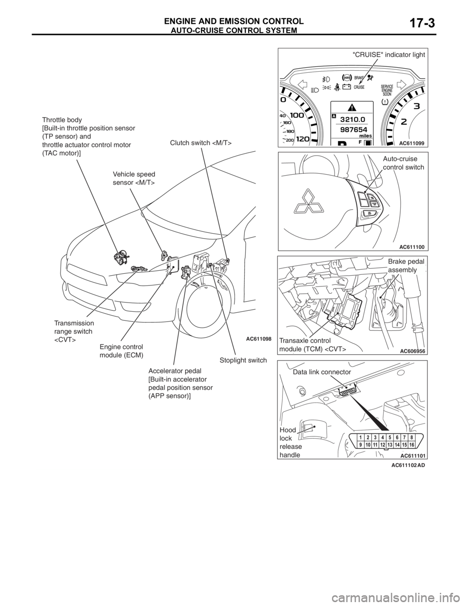
AUTO-CRUISE CONTROL SYSTEM
ENGINE AND EMISSION CONTROL17-3
AC611102 AC611098
AC611099
AC611100
AC606956
AC611101
Auto-cruise
control switch
Data link connector
Hood
lock
release
handle
AD
Clutch switch
Stoplight switch
Accelerator pedal
[Built-in accelerator
pedal position sensor
(APP sensor)] Engine control
module (ECM)"CRUISE" indicator light
Transaxle control
module (TCM)
Brake pedal
assembly
Throttle body
[Built-in throttle position sensor
(TP sensor) and
throttle actuator control motor
(TAC motor)]
Transmission
range switch
Vehicle speed
sensor
Page 66 of 241

AUTO-CRUISE CONTROL SYSTEM
ENGINE AND EMISSION CONTROL17-4
COMPONENTS AND FUNCTIONS
ComponentFunction
Accelerator pedal position sensor (APP sensor)Informs the ECM of the accelerator pedal
depression.
Auto-cruise control switch"ON/OFF" switchPower switch for auto-cruise control system.
"ACC/RES" switchVehicle speed is set with the "ACC/RES" switch and
"COAST/SET" switch.
"COAST/SET" switch
"CANCEL" switchCancels the cruise speed setting.
Cancel systemClutch switch
the clutch operation, the clutch pedal status is
detected.
Stoplight switch•Because the constant speed driving is canceled
by the brake operation, it detects the brake pedal
status.
•As for the stoplight switch, two built-in switches,
the stoplight switch which is also used for the
stoplight illumination and the brake switch which
is used exclusively for the auto-cruise control, are
integrated, and thus the reliability is enhanced.
Transmission range
switch
the selector lever operation, it detects the "N"
position.
"CRUISE" indicator lightThe light is included in the combination meter and
illuminates when the "ON/OFF" switch is pressed
(auto-cruise control system: ON).
Data link connectorIf the M.U.T.-III scan tool is connected, the input
check code from the ECM can be read.
Engine control module (ECM)•Based on the input signal from each sensor and
switch, it outputs the throttle opening instruction
signal to the TAC motor.
•Based on the input signal from each sensor and
switch, it outputs the transaxle control signal to
the TCM
•Based on the vehicle speed signal from the
vehicle speed sensor, it calculates the vehicle
speed
•Based on the secondary pulley speed sensor
signal from the TCM, it calculates the vehicle
speed
•Based on the selector lever "N" position signal of
the transmission range switch from the ECM, it
cancels constant speed driving.
•Outputs the ON/OFF signals of "CRUISE"
indicator light and auto-cruise control system.
•The diagnostic trouble code signal is sent to the
"CRUISE" indicator light.
•The input check code is sent to the data link
connector.
Throttle actuator control motor (TAC motor)The throttle valve opens and closes in response to
the throttle angle signal from the ECM.
Page 67 of 241
AUTO-CRUISE CONTROL SYSTEM
ENGINE AND EMISSION CONTROL17-5
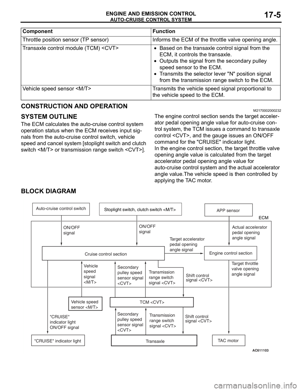
CONSTRUCTION AND OPERATIONM2170002000232
SYSTEM OUTLINE
The ECM calculates the auto-cruise control system
operation status when the ECM receives input sig
-
nals from the auto-cruise control switch, vehicle
speed and cancel system [stoplight switch and clutch
switch
-
ator pedal opening angle value for auto-cruise con-
trol system, the TCM issues a command to transaxle
control
command for the "CRUISE" indicator light.
In the engine control section, the target throttle valve
opening angle value is calculated from the target
accelerator pedal opening angle value for
auto-cruise control system and the actual accelerator
angle value.The vehicle speed is then controlled by
applying the TAC motor.
BLOCK DIAGRAM
Throttle position sensor (TP sensor)Informs the ECM of the throttle valve opening angle.
Transaxle control module (TCM)
ECM, it controls the transaxle.
•Outputs the signal from the secondary pulley
speed sensor to the ECM.
•Transmits the selector lever "N" position signal
from the transmission range switch to the ECM.
Vehicle speed sensor
the vehicle speed to the ECM.
Component Function
TAC motor Target accelerator
pedal opening
angle signal
Engine control section
Cruise control section"CRUISE" indicator light
AC611103
Actual accelerator
pedal opening
angle signal
Shift control
signal
Target throttle
valve opening
angle signal
Auto-cruise control switch
ECM
Stoplight switch, clutch switch
TCM
"CRUISE"
indicator light
ON/OFF signal
APP sensor
Transmission
range switch
signal
signal
TransaxleTransmission
range switch
signal
Secondary
pulley speed
sensor signal
signalON/OFF
signal
Vehicle speed
sensor
Vehicle
speed
signal
pulley speed
sensor signal
Page 71 of 241
EMISSION CONTROL
ENGINE AND EMISSION CONTROL17-9
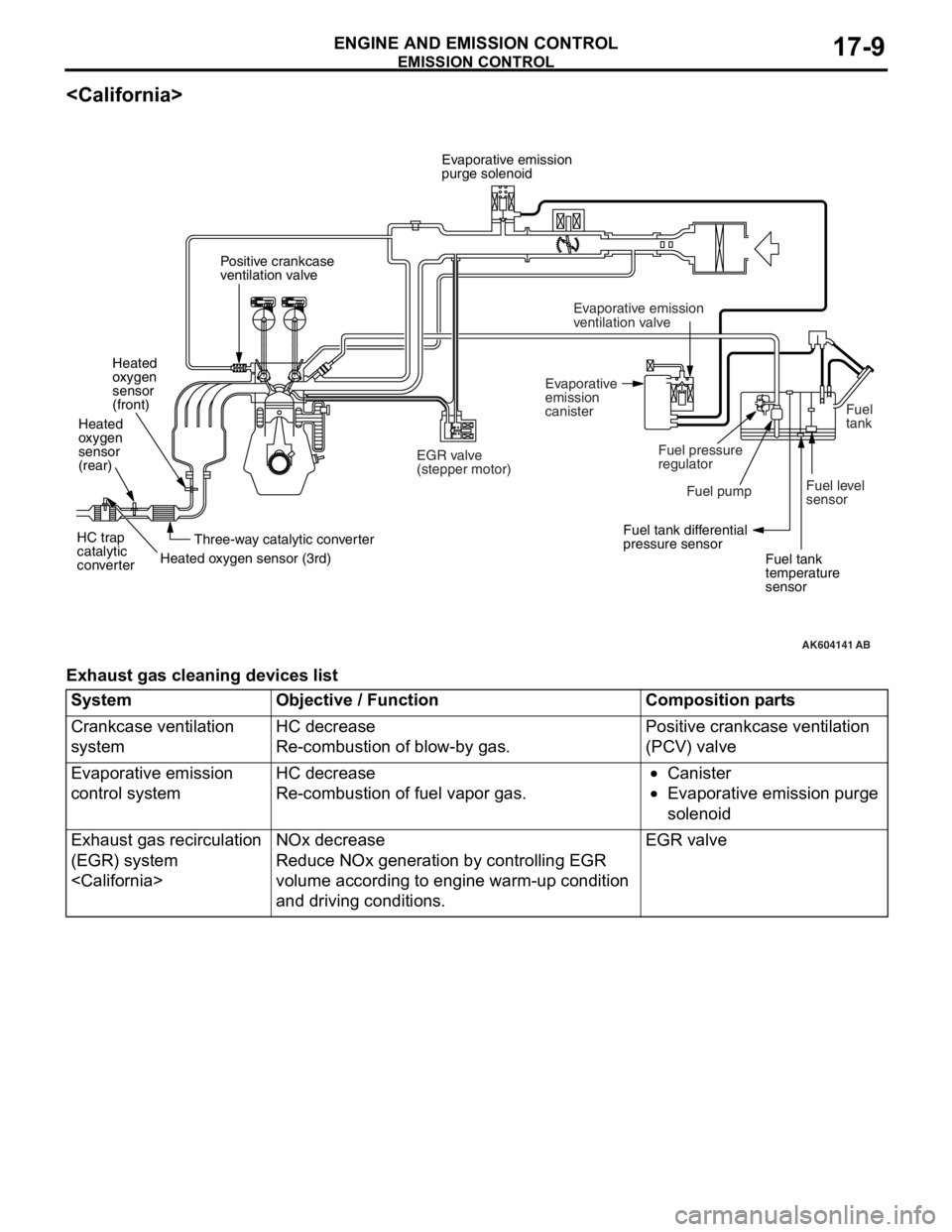
Exhaust gas cleaning devices list
AK604141
Three-way catalytic converter Heated
oxygen
sensor
(front)
Heated
oxygen
sensor
(rear)
HC trap
catalytic
converterHeated oxygen sensor (3rd)Positive crankcase
ventilation valve
EGR valve
(stepper motor)
AB
Fuel level
sensorFuel
tank
Fuel tank differential
pressure sensor
Fuel tank
temperature
sensor Fuel pump Fuel pressure
regulator Evaporative emission
purge solenoid
Evaporative
emission
canisterEvaporative emission
ventilation valve
SystemObjective / FunctionComposition parts
Crankcase ventilation
systemHC decrease
Re-combustion of blow-by gas.
Positive crankcase ventilation
(PCV) valve
Evaporative emission
control systemHC decrease
Re-combustion of fuel vapor gas.
•Canister
•Evaporative emission purge
solenoid
Exhaust gas recirculation
(EGR) system
Reduce NOx generation by controlling EGR
volume according to engine warm-up condition
and driving conditions.
EGR valve
Page 74 of 241
EMISSION CONTROL
ENGINE AND EMISSION CONTROL17-12
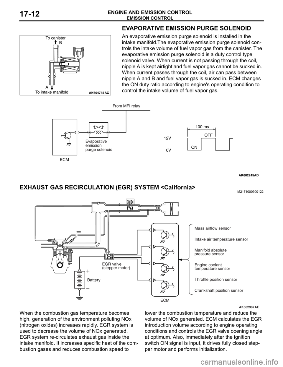
EVAPORATIVE EMISSION PURGE SOLENOID
An evaporative emission purge solenoid is installed in the
intake manifold.The evaporative emission purge solenoid con
-
trols the intake volume of fuel vapor gas from the canister. The
evaporative emission purge solenoid is a duty control type
solenoid valve. When current is not passing through the coil,
nipple A is kept airtight and fuel vapor gas cannot be sucked in.
When current passes through the coil, air can pass between
nipple A and B and fuel vapor gas is sucked in. ECM changes
the ON duty ratio according to engine's operating condition to
control the intake volume of fuel vapor gas.
EXHAUST GAS RECIRCULATION (EGR) SYSTEM
When the combustion gas temperature becomes
high, generation of the environment polluting NOx
(nitrogen oxides) increases rapidly. EGR system is
used to decrease the volume of NOx generated.
EGR system re-circulates exhaust gas inside the
intake manifold. It increases specific heat of the com
-
bustion gases and reduces combustion speed to lower the combustion temperature and reduce the
volume of NOx generated. ECM calculates the EGR
introduction volume according to engine operating
conditions and controls the EGR valve opening angle
at optimum. Also, immediately after the ignition
switch ON signal is input, it drives fully closed step
-
per motor and performs initialization.
AK604745AC
B To canister
To intake manifoldA
AK602245AD
12V
ONOFF
0V100 ms
Evaporative
emission
purge solenoidFrom MFI relay
ECM
AK502987AE
ECMMass airflow sensor
Intake air temperature sensor
Manifold absolute
pressure sensor
Engine coolant
temperature sensor
Throttle position sensor
Crankshaft position sensor BatteryEGR valve
(stepper motor)
Page 75 of 241
EMISSION CONTROL
ENGINE AND EMISSION CONTROL17-13
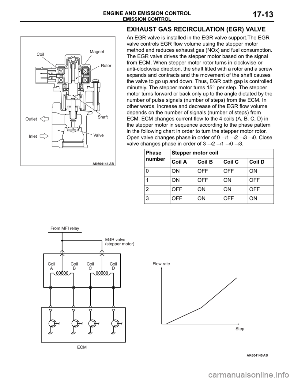
EXHAUST GAS RECIRCULATION (EGR) VALVE
An EGR valve is installed in the EGR valve support.The EGR
valve controls EGR flow volume using the stepper motor
method and reduces exhaust gas (NOx) and fuel consumption.
The EGR valve drives the stepper motor based on the signal
from ECM. When stepper motor rotor turns in clockwise or
anti-clockwise direction, the shaft fitted with a rotor and a screw
expands and contracts and the movement of the shaft causes
the valve to go up and down. Thus, EGR path gap is controlled
minutely. The stepper motor turns 15
° per step. The stepper
motor turns forward or back only up to the angle dictated by the
number of pulse signals (number of steps) from the ECM. In
other words, increase and decrease of the EGR flow volume
depends on the number of signals (number of steps) from
ECM. ECM changes current flow to the 4 coils (A, B, C, D) in
the stepper motor in sequence according to the phase pattern
in the following chart in order to turn the stepper motor rotor.
Open valve changes phase in order of 0
→ 1 → 2 → 3 → 0. Close
valve changes phase in order of 3
→ 2 → 1 → 0 → 3.
Phase
numberStepper motor coil
Coil ACoil BCoil CCoil D
0ONOFFOFFON
1ONOFFONOFF
2OFFONONOFF
3OFFONOFFON
AK604144
Coil
Shaft
Valve Outlet
Inlet
Rotor
Magnet
AB
AK604145
From MFI relay
EGR valve
(stepper motor)
ECM Coil
ACoil
BCoil
CCoil
DFlow rate
Step
AB
Page 79 of 241
16-1
GROUP 16
ENGINE
ELECTRICAL
CONTENTS
STARTER MOTOR . . . . . . . . . . . . . .16-2
ALTERNATOR . . . . . . . . . . . . . . . . . .16-2
IGNITION COIL . . . . . . . . . . . . . . . . . .16-2
SPARK PLUG . . . . . . . . . . . . . . . . . . .16-3