Motor MITSUBISHI LANCER EVOLUTION X 2008 User Guide
[x] Cancel search | Manufacturer: MITSUBISHI, Model Year: 2008, Model line: LANCER EVOLUTION X, Model: MITSUBISHI LANCER EVOLUTION X 2008Pages: 241, PDF Size: 8.26 MB
Page 80 of 241
STARTER MOTOR
ENGINE ELECTRICAL16-2
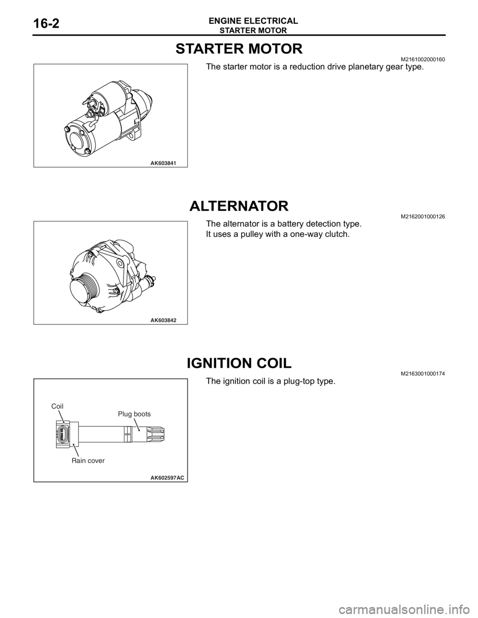
STARTER MOTORM2161002000160
The starter motor is a reduction drive planetary gear type.
ALTERNATORM2162001000126
The alternator is a battery detection type.
It uses a pulley with a one-way clutch.
IGNITION COILM2163001000174
The ignition coil is a plug-top type.
AK603841
AK603842
AK602597
Plug boots
Rain cover Coil
AC
Page 88 of 241

GENERAL INFORMATION
ENGINE COOLING14-2
GENERAL INFORMATIONM2140000100780
The cooling system is a water-cooled pressurized,
forced circulation type which offers the following fea
-
tures.
•To stabilize engine coolant temperature, the ther-
mostat is located at the coolant inlet port from the
radiator.
•To improve engine cooling performance and save
weight, a plastic tank and aluminum radiator fins
are used.
SPECIFICATIONS
CONSTRUCTION DIAGRAM
ItemSpecification
Cooling methodWater-cooled pressurized, forced
circulation with electrical fan
RadiatorTy p ePressurized corrugate type
Performance kJ/h (kcal/h)222,480 (53,148)
Water pumpTy p eCentrifugal impeller
Drive methodDrive belt
ThermostatTy p eWax pellet with jiggle valve
Valve open temperature °C (°F)82 (180)
AC608448
Condenser fan motor Radiator assemblyRadiator upper hose
assembly
Radiator condenser
tank assembly Radiator fan motor
Cooling fan shroud
Radiator lower hose Transmission oil
cooler line hose
and tube assembly
AB
Page 97 of 241
GENERAL DESCRIPTION
MULTIPORT FUEL SYSTEM (MFI)13A-3
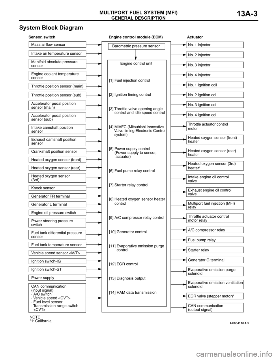
System Block Diagram
AK604116
Mass airflow sensor
Intake air temperature sensor
Intake camshaft position
sensor
Exhaust camshaft position
sensor
Crankshaft position sensor Throttle position sensor (main)
Throttle position sensor (sub)
Accelerator pedal position
sensor (sub) Accelerator pedal position
sensor (main) Engine coolant temperature
sensor Manifold absolute pressure
sensor
Heated oxygen sensor (front)
Heated oxygen sensor (rear)
Power steering pressure
switch Engine oil pressure switch Generator L terminal
Ignition switch-ST
Power supply Ignition switch-IG
CAN communication
(input signal)
· A/C switch
· Vehicle speed
· Fuel level sensor
· Transmission range switch
sensor Heated oxygen sensor
(3rd)*
Knock sensor
Generator FR terminal
Fuel tank temperature sensor
Vehicle speed sensor
[1] Fuel injection control
[2] Ignition timing control
[3] Throttle valve opening angle
control and idle speed control
[4]
MIVEC (Mitsubishi Innovative
Valve timing Electronic Control
system)
[5] Power supply control
(Power supply to sensor,
actuator)
[6] Fuel pump relay control
[7] Starter relay control
[8] Heated oxygen sensor heater
control
[9] A/C compressor relay control
[10] Generator control
[11] Evaporative emission purge
control
[12] EGR control
[13] Diagnosis output
[14] RAM data transmission
CAN communication
(output signal) Intake engine oil control
valve
A/C compressor relay No. 2 injector
No. 3 injector
No. 4 injector
Heated oxygen sensor (front)
heater
Heated oxygen sensor (rear)
heater Throttle actuator control
motor
Throttle actuator control
motor relay No. 1 injector
No. 1 ignition coil
No. 2 ignition coi
No. 3 ignition coi
No. 4 ignition coi
Fuel pump relay
Generator G terminal Heated oxygen sensor (3rd)
heater*
Multiport fuel injection (MFI)
relay Exhaust engine oil control
valve
Evaporative emission ventilation
solenoid Evaporative emission purge
solenoid
EGR valve (stepper motor)*
Starter relay
AB
Sensor, switch Engine control module (ECM) Actuator
NOTE
*1: California
Page 98 of 241
GENERAL DESCRIPTION
MULTIPORT FUEL SYSTEM (MFI)13A-4
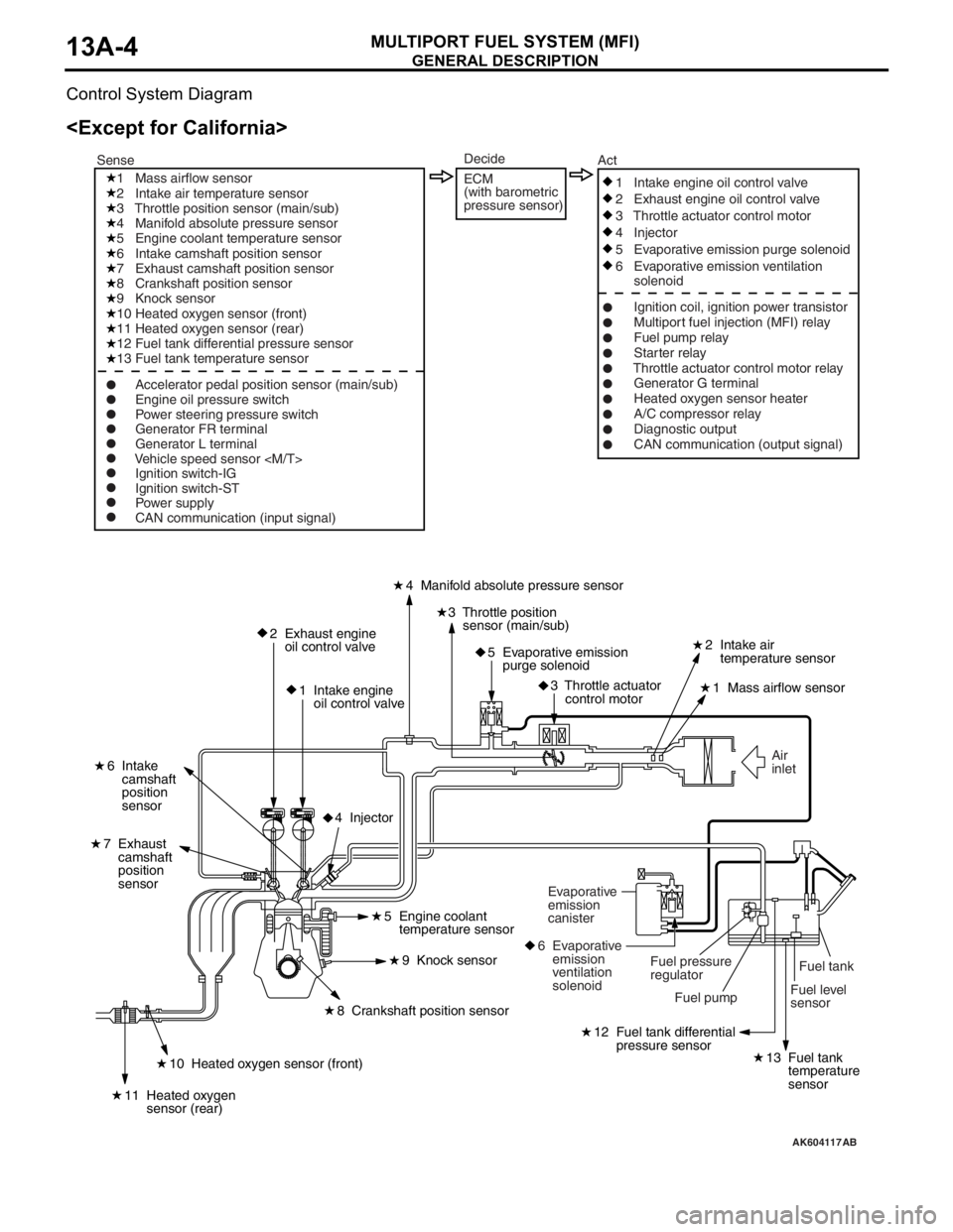
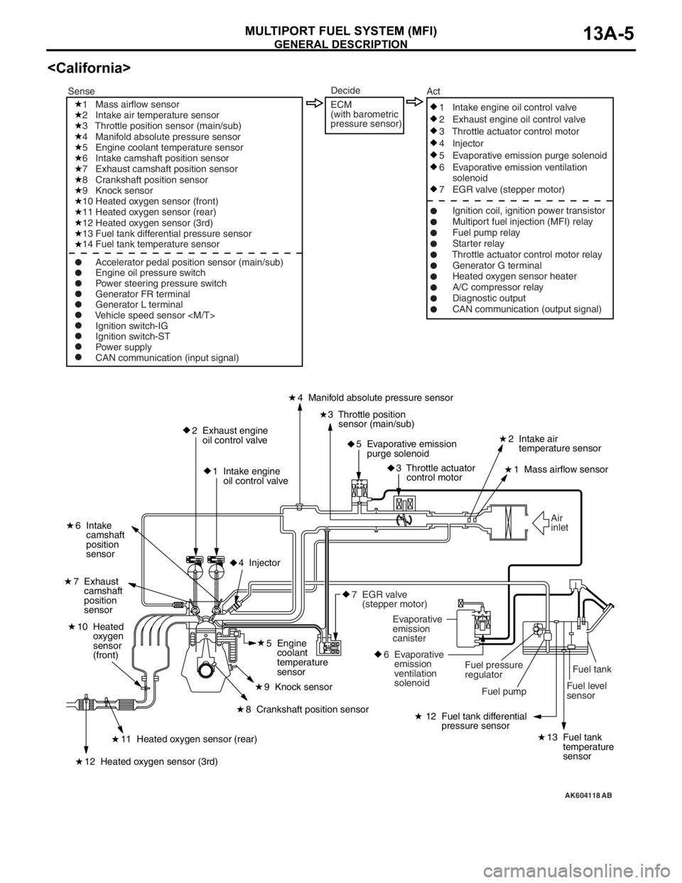
Control System Diagram
AK604117
Fuel level
sensorFuel tank Air
inlet
2 Exhaust engine
oil control valve
1 Intake engine
oil control valve4 Manifold absolute pressure sensor
2 Intake air
temperature sensor
1 Mass airflow sensor
6 Intake
camshaft
position
sensor
7 Exhaust
camshaft
position
sensor
3 Throttle position
sensor (main/sub)
5 Evaporative emission
purge solenoid
3 Throttle actuator
control motor
12 Fuel tank differential
pressure sensor
13 Fuel tank
temperature
sensor10 Heated oxygen sensor (front)
11 Heated oxygen
sensor (rear)
8 Crankshaft position sensor5 Engine coolant
temperature sensor
9 Knock sensor
4 Injector
Fuel pump Fuel pressure
regulator Evaporative
emission
canister
6 Evaporative
emission
ventilation
solenoid
1 Mass airflow sensor
2 Intake air temperature sensor
3 Throttle position sensor (main/sub)
4 Manifold absolute pressure sensor
5 Engine coolant temperature sensor
6 Intake camshaft position sensor
7 Exhaust camshaft position sensor
8 Crankshaft position sensor
9 Knock sensor
10 Heated oxygen sensor (front)
11 Heated oxygen sensor (rear)
12 Fuel tank differential pressure sensor
13 Fuel tank temperature sensor
Ignition switch-IG
Ignition switch-ST
Power supply
CAN communication (input signal)1 Intake engine oil control valve
2 Exhaust engine oil control valve
3 Throttle actuator control motor
4 Injector
5 Evaporative emission purge solenoid
6 Evaporative emission ventilation
solenoid
Ignition coil, ignition power transistor
Multiport fuel injection (MFI) relay
Fuel pump relay
Starter relay
Throttle actuator control motor relay
Generator G terminal
Heated oxygen sensor heater
A/C compressor relay
Diagnostic output
CAN communication (output signal) SenseAct
Engine oil pressure switch
Power steering pressure switch
Generator FR terminal
Generator L terminal
Vehicle speed sensor
Decide
ECM
(with barometric
pressure sensor)
AB
Page 99 of 241
GENERAL DESCRIPTION
MULTIPORT FUEL SYSTEM (MFI)13A-5
AK604118
Fuel tank
Fuel level
sensor Air
inlet
2 Exhaust engine
oil control valve
1 Intake engine
oil control valve4 Manifold absolute pressure sensor
2 Intake air
temperature sensor
1 Mass airflow sensor
6 Intake
camshaft
position
sensor
7 Exhaust
camshaft
position
sensor
3 Throttle position
sensor (main/sub)
5 Evaporative emission
purge solenoid
3 Throttle actuator
control motor
12 Fuel tank differential
pressure sensor
13 Fuel tank
temperature
sensor11 Heated oxygen sensor (rear)
10 Heated
oxygen
sensor
(front)
12 Heated oxygen sensor (3rd)
8 Crankshaft position sensor5 Engine
coolant
temperature
sensor
9 Knock sensor
4 Injector
Fuel pump Fuel pressure
regulator Evaporative
emission
canister
6 Evaporative
emission
ventilation
solenoid
7 EGR valve
(stepper motor)
1 Mass airflow sensor
2 Intake air temperature sensor
3 Throttle position sensor (main/sub)
4 Manifold absolute pressure sensor
5 Engine coolant temperature sensor
6 Intake camshaft position sensor
7 Exhaust camshaft position sensor
8 Crankshaft position sensor
9 Knock sensor
10 Heated oxygen sensor (front)
11 Heated oxygen sensor (rear)
12 Heated oxygen sensor (3rd)
13 Fuel tank differential pressure sensor
14 Fuel tank temperature sensor
Ignition switch-IG
Ignition switch-ST
Power supply
CAN communication (input signal)1 Intake engine oil control valve
2 Exhaust engine oil control valve
3 Throttle actuator control motor
4 Injector
5 Evaporative emission purge solenoid
6 Evaporative emission ventilation
solenoid
7 EGR valve (stepper motor)
Ignition coil, ignition power transistor
Multiport fuel injection (MFI) relay
Fuel pump relay
Starter relay
Throttle actuator control motor relay
Generator G terminal
Heated oxygen sensor heater
A/C compressor relay
Diagnostic output
CAN communication (output signal) SenseAct
Engine oil pressure switch
Power steering pressure switch
Generator FR terminal
Generator L terminal
Vehicle speed sensor
Decide
ECM
(with barometric
pressure sensor)
AB
Page 103 of 241
SENSOR
MULTIPORT FUEL SYSTEM (MFI)13A-10
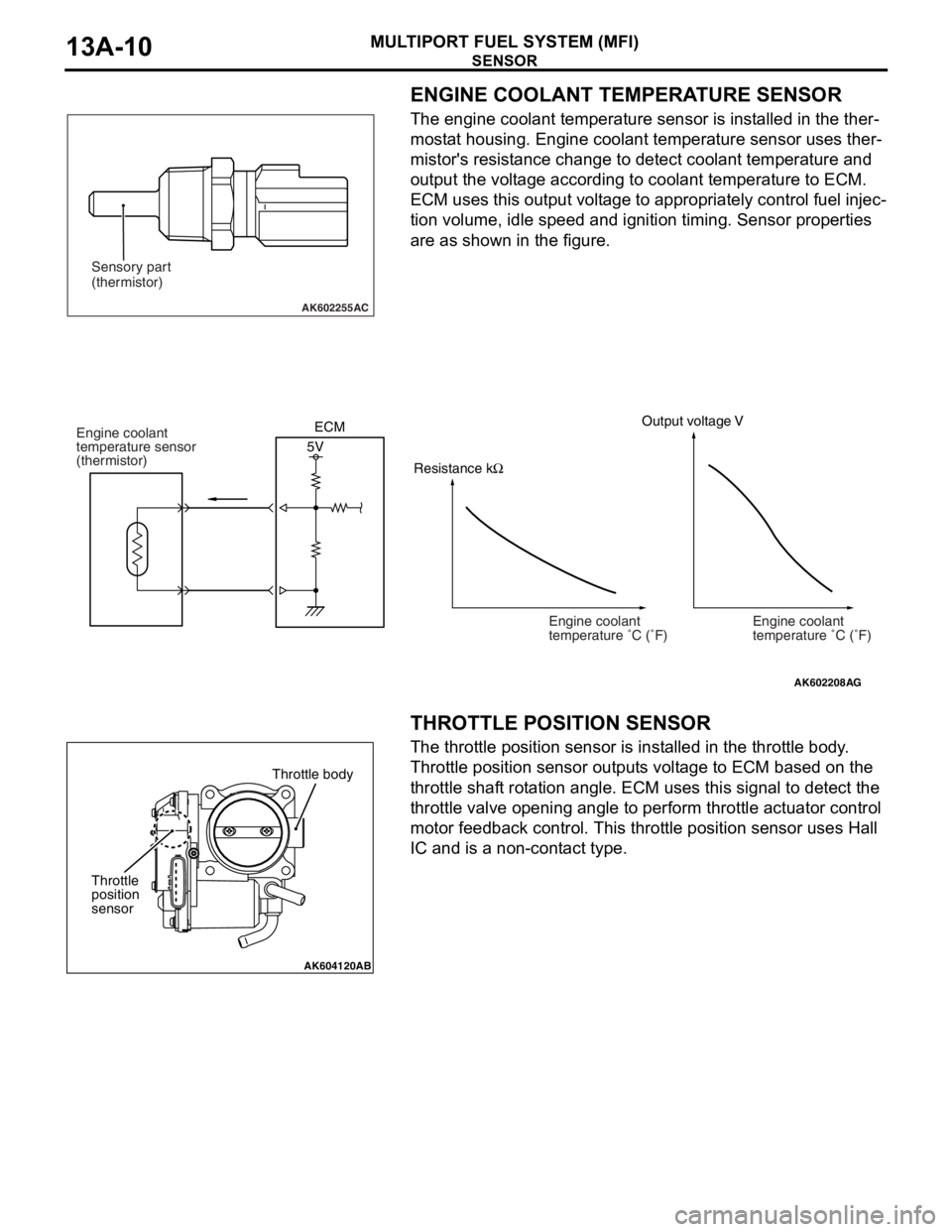
ENGINE COOLANT TEMPERATURE SENSOR
The engine coolant temperature sensor is installed in the ther-
mostat housing. Engine coolant temperature sensor uses ther-
mistor's resistance change to detect coolant temperature and
output the voltage according to coolant temperature to ECM.
ECM uses this output voltage to appropriately control fuel injec
-
tion volume, idle speed and ignition timing. Sensor properties
are as shown in the figure.
.
THROTTLE POSITION SENSOR
The throttle position sensor is installed in the throttle body.
Throttle position sensor outputs voltage to ECM based on the
throttle shaft rotation angle. ECM uses this signal to detect the
throttle valve opening angle to perform throttle actuator control
motor feedback control. This throttle position sensor uses Hall
IC and is a non-contact type.
.
AK602255AC
Sensory part
(thermistor)
AK602208
Engine coolant
temperature �C (�F)
AG
Output voltage V
5V Engine coolant
temperature sensor
(thermistor)
Engine coolant
temperature �C (�F) ECM
Resistance kΩ
AK604120AB
Throttle body
Throttle
position
sensor
Page 104 of 241
SENSOR
MULTIPORT FUEL SYSTEM (MFI)13A-11
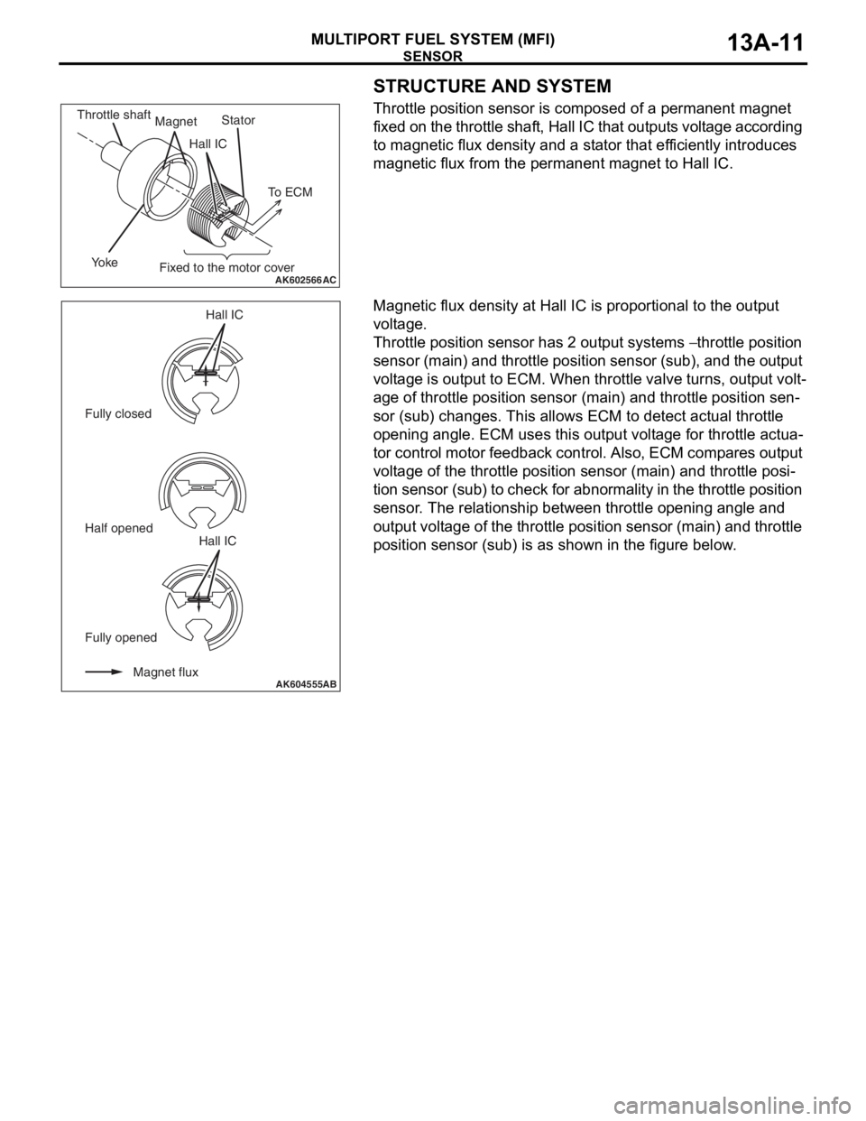
STRUCTURE AND SYSTEM
Throttle position sensor is composed of a permanent magnet
fixed on the throttle shaft, Hall IC that outputs voltage according
to magnetic flux density and a stator that efficiently introduces
magnetic flux from the permanent magnet to Hall IC.
Magnetic flux density at Hall IC is proportional to the output
voltage.
Throttle position sensor has 2 output systems − throttle position
sensor (main) and throttle position sensor (sub), and the output
voltage is output to ECM. When throttle valve turns, output volt
-
age of throttle position sensor (main) and throttle position sen-
sor (sub) changes. This allows ECM to detect actual throttle
opening angle. ECM uses this output voltage for throttle actua
-
tor control motor feedback control. Also, ECM compares output
voltage of the throttle position sensor (main) and throttle posi
-
tion sensor (sub) to check for abnormality in the throttle position
sensor. The relationship between throttle opening angle and
output voltage of the throttle position sensor (main) and throttle
position sensor (sub) is as shown in the figure below.
AK602566AC
Hall ICStator
Yo k e
Fixed to the motor cover Magnet Throttle shaft
To ECM
AK604555Magnet flux Fully opened Fully closedHall IC
Half opened
Hall ICAB
Page 114 of 241
SENSOR
MULTIPORT FUEL SYSTEM (MFI)13A-21
.
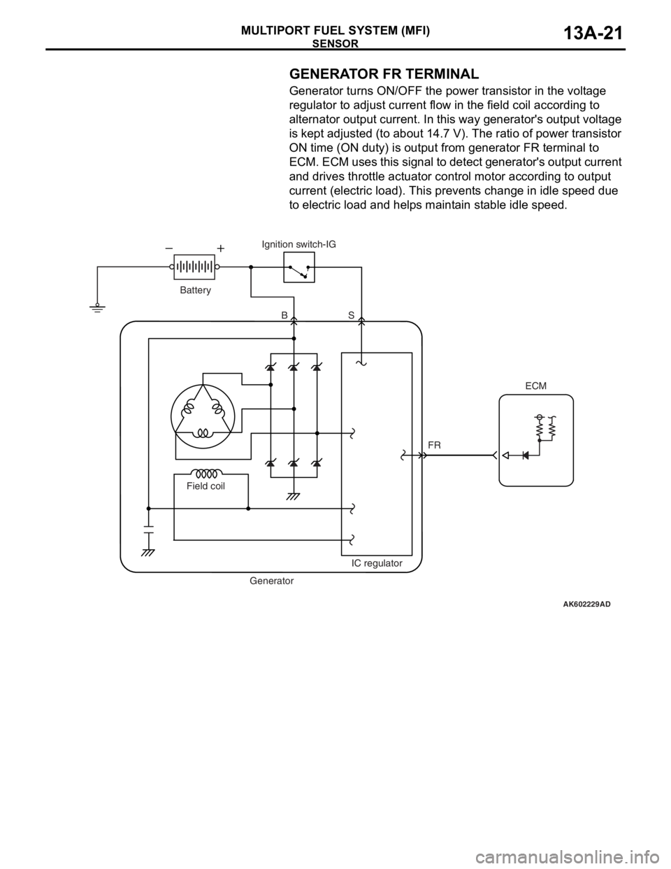
GENERATOR FR TERMINAL
Generator turns ON/OFF the power transistor in the voltage
regulator to adjust current flow in the field coil according to
alternator output current. In this way generator's output voltage
is kept adjusted (to about 14.7 V). The ratio of power transistor
ON time (ON duty) is output from generator FR terminal to
ECM. ECM uses this signal to detect generator's output current
and drives throttle actuator control motor according to output
current (electric load). This prevents change in idle speed due
to electric load and helps maintain stable idle speed.
.
AK602229AD
FR BS
Field coil
IC regulator
GeneratorIgnition switch-IG
Battery
ECM
Page 117 of 241
ACTUATOR
MULTIPORT FUEL SYSTEM (MFI)13A-24
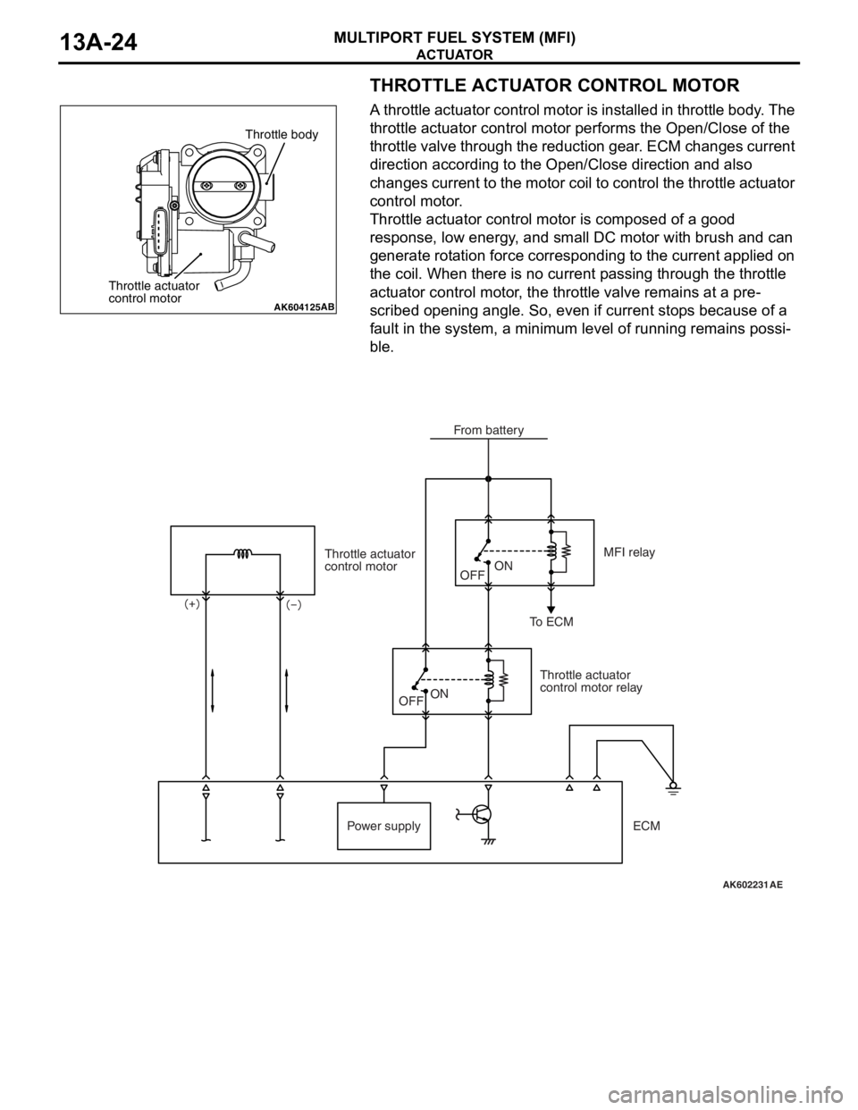
THROTTLE ACTUATOR CONTROL MOTOR
A throttle actuator control motor is installed in throttle body. The
throttle actuator control motor performs the Open/Close of the
throttle valve through the reduction gear. ECM changes current
direction according to the Open/Close direction and also
changes current to the motor coil to control the throttle actuator
control motor.
Throttle actuator control motor is composed of a good
response, low energy, and small DC motor with brush and can
generate rotation force corresponding to the current applied on
the coil. When there is no current passing through the throttle
actuator control motor, the throttle valve remains at a pre
-
scribed opening angle. So, even if current stops because of a
fault in the system, a minimum level of running remains possi
-
ble.
AK604125AB
Throttle body
Throttle actuator
control motor
AK602231
Throttle actuator
control motor
Throttle actuator
control motor relayMFI relay
To ECM
Power supplyOFFON
OFF
ON
AE
From battery
ECM
Page 131 of 241
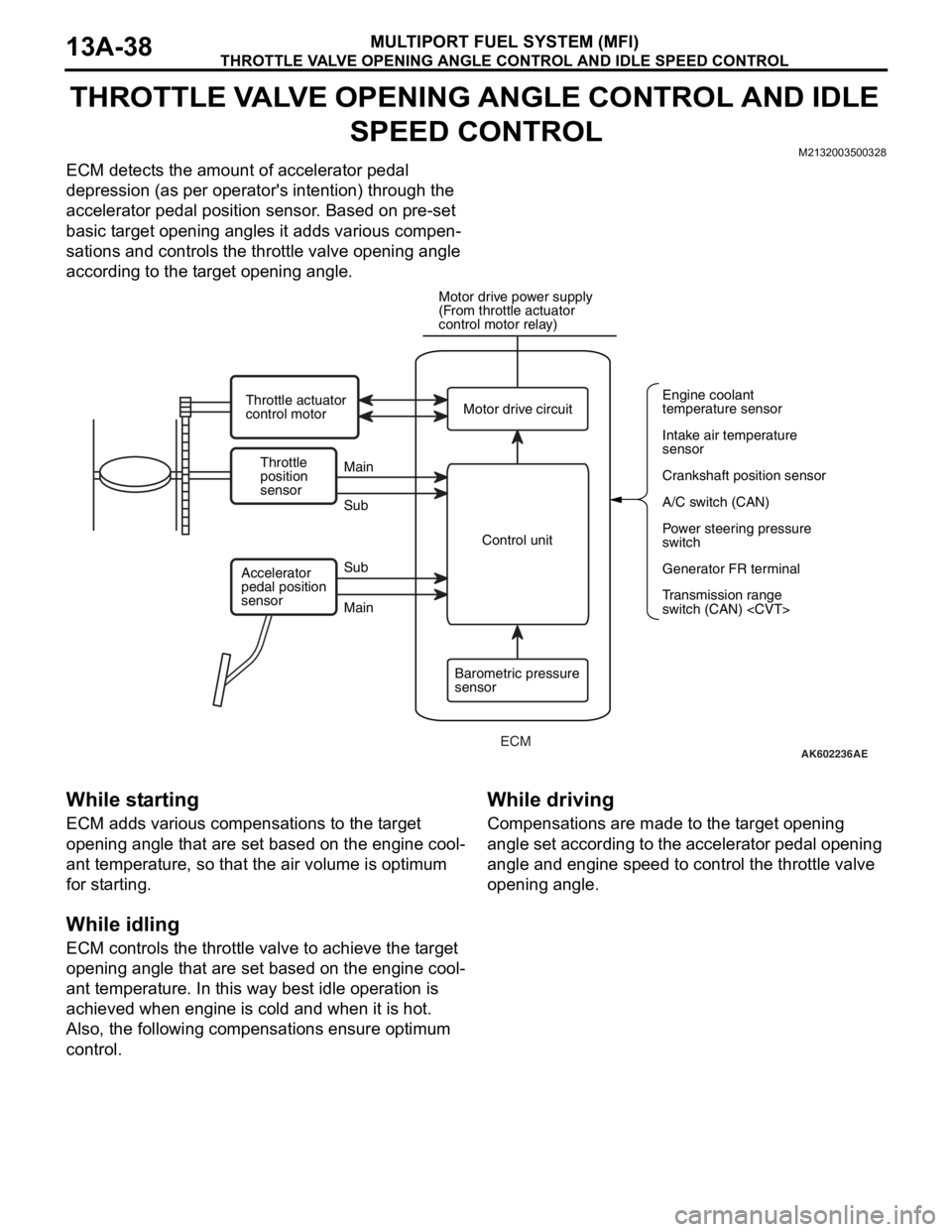
THROTTLE VALVE OPENING ANGLE CONTROL AND IDLE SPEED CONTROL
MULTIPORT FUEL SYSTEM (MFI)13A-38
THROTTLE VALVE OPENING ANGLE CONTROL AND IDLE
SPEED CONTROL
M2132003500328
ECM detects the amount of accelerator pedal
depression (as per operator's intention) through the
accelerator pedal position sensor. Based on pre-set
basic target opening angles it adds various compen
-
sations and controls the throttle valve opening angle
according to the target opening angle.
While starting
ECM adds various compensations to the target
opening angle that are set based on the engine cool
-
ant temperature, so that the air volume is optimum
for starting.
While idling
ECM controls the throttle valve to achieve the target
opening angle that are set based on the engine cool
-
ant temperature. In this way best idle operation is
achieved when engine is cold and when it is hot.
Also, the following compensations ensure optimum
control.
While driving
Compensations are made to the target opening
angle set according to the accelerator pedal opening
angle and engine speed to control the throttle valve
opening angle.
AK602236AE
Throttle
position
sensorMain
Main Sub
SubMotor drive circuit
A/C switch (CAN) Engine coolant
temperature sensor
Intake air temperature
sensor
Crankshaft position sensor
Power steering pressure
switch
Generator FR terminal
Transmission range
switch (CAN)
(From throttle actuator
control motor relay)
Throttle actuator
control motor
Control unit
Barometric pressure
sensor Accelerator
pedal position
sensor
ECM