compression ratio MITSUBISHI LANCER EVOLUTION X 2008 Workshop Manual
[x] Cancel search | Manufacturer: MITSUBISHI, Model Year: 2008, Model line: LANCER EVOLUTION X, Model: MITSUBISHI LANCER EVOLUTION X 2008Pages: 241, PDF Size: 8.26 MB
Page 46 of 241

GENERAL DESCRIPTION
ENGINE MECHANICAL11A-2
GENERAL DESCRIPTIONM2112000101162
This model is equipped with a newly developed 4B11
engine. It is a 4-cylinder, double overhead camshaft
(DOHC) engine with a 2.0-L cylinder displacement.
This engine has adopted the following features:
•MIVEC (MITSUBISHI INNOVATIVE VALVE TIM-
ING ELECTRONIC CONTROL SYSTEM) for
both the intake and exhaust valves
•Cylinder block made of an aluminum alloy
•Valve train with direct-acting valve tappets
•Silent timing chain
MAIN SPECIFICATIONS
DescriptionsSpecifications
Engine type4B11
Bore × stroke mm (in)86 (3.4) × 86 (3.4)
Total displacement cm3 (cu in)1,998 (121.9)
Combustion chamberPent-roof type
Number of cylinders4
Valve mechanismTy p eDOHC
Intake valve8
Exhaust valve8
Compression ratio10.0
Va l v e t i m i n gIntake valveOpens (BTDC)3° − 28°
0° − 25°
Closes (ABDC)45° − 20°
48° − 23°
Exhaust valveOpens (BBDC)41° − 21°
44° − 24°
Closes (ATDC)3° − 23°
0° − 20°
Maximum output kW/r/min (HP/r/min)107/6,000 (143/6,000)
113/6,000 (152/6,000)
Maximum torque N⋅m/r/min (lbs-ft/r/min)194/4,250 (143/4,250)
198/4,250 (146/4,250)
Fuel injection system typeElectronic control MPI
Ignition system typeElectronic spark-advance control type (4-coil
type)
Generator typeAlternating current system (with built-in IC
regulator)
Starter motor typeReduction drive type
Page 123 of 241

FUEL INJECTION CONTROL
MULTIPORT FUEL SYSTEM (MFI)13A-30
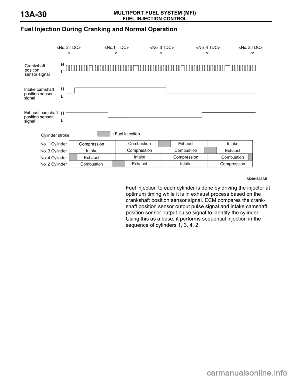
Fuel Injection During Cranking and Normal Operation
Fuel injection to each cylinder is done by driving the injector at
optimum timing while it is in exhaust process based on the
crankshaft position sensor signal. ECM compares the crank
-
shaft position sensor output pulse signal and intake camshaft
position sensor output pulse signal to identify the cylinder.
Using this as a base, it performs sequential injection in the
sequence of cylinders 1, 3, 4, 2.
AK604622AB
Cylinder stroke
No. 1 Cylinder
No. 3 Cylinder
No. 4 Cylinder
No. 2 CylinderCombustion
Intake
Exhaust
CombustionExhaust
Compression: Fuel injection
Intake
Exhaust CompressionCombustion
Intake CompressionIntake
Exhaust
Combustion
Compression
H
L H
L
H
L Crankshaft
position
sensor signal
Intake camshaft
position sensor
signal
Exhaust camshaft
position sensor
signal
Page 124 of 241

FUEL INJECTION CONTROL
MULTIPORT FUEL SYSTEM (MFI)13A-31
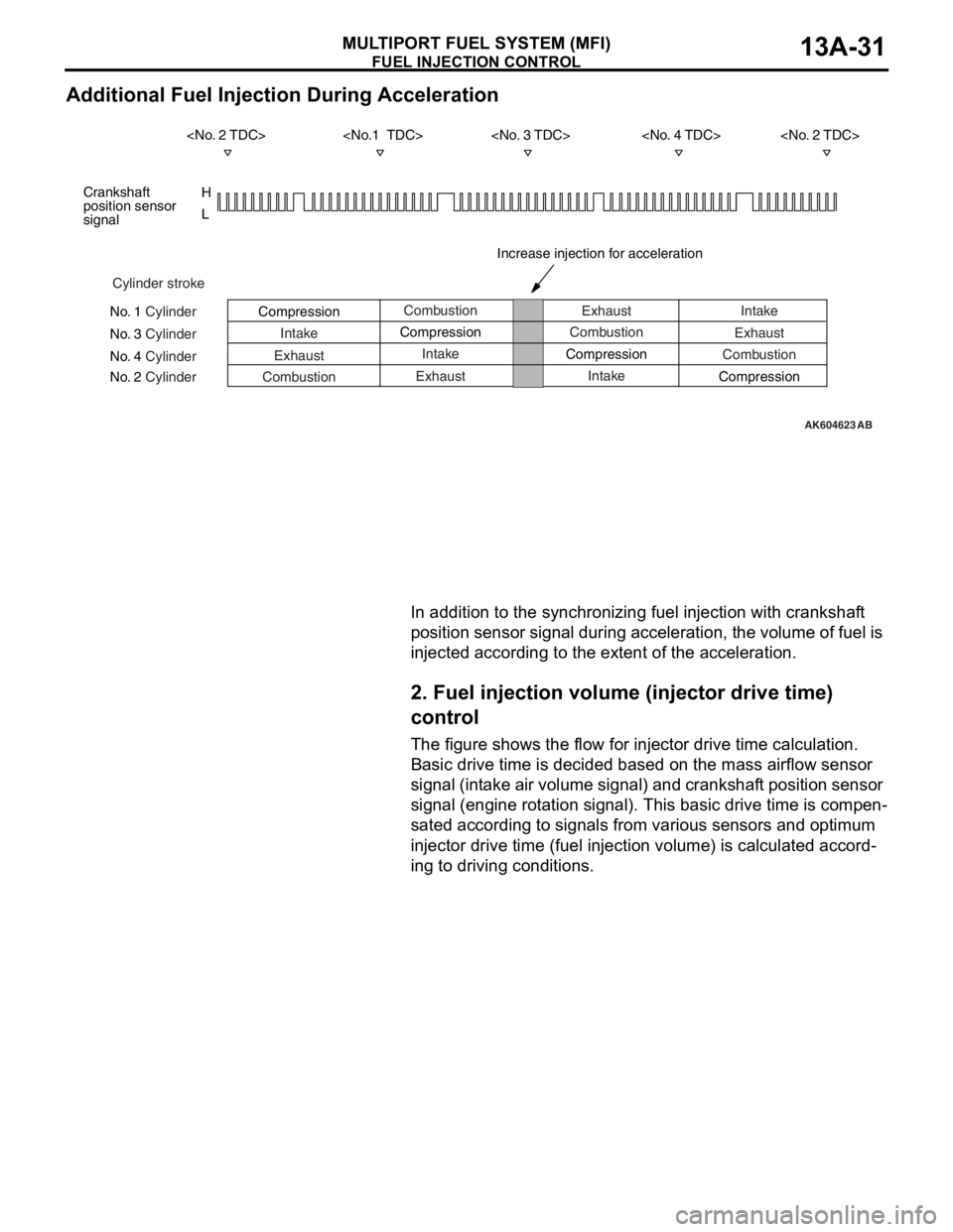
Additional Fuel Injection During Acceleration
In addition to the synchronizing fuel injection with crankshaft
position sensor signal during acceleration, the volume of fuel is
injected according to the extent of the acceleration.
2. Fuel injection volume (injector drive time)
control
The figure shows the flow for injector drive time calculation.
Basic drive time is decided based on the mass airflow sensor
signal (intake air volume signal) and crankshaft position sensor
signal (engine rotation signal). This basic drive time is compen
-
sated according to signals from various sensors and optimum
injector drive time (fuel injection volume) is calculated accord
-
ing to driving conditions.
AK604623
H
L
AB
Cylinder stroke
No. 1 Cylinder
No. 3 Cylinder
No. 4 Cylinder
No. 2 CylinderCombustion
Intake
Exhaust
CombustionExhaust
Compression
Intake
Exhaust CompressionCombustion
Intake CompressionIntake
Exhaust
Combustion
Compression Crankshaft
position sensor
signal
Increase injection for acceleration