torque MITSUBISHI LANCER EVOLUTION X 2008 Workshop Manual
[x] Cancel search | Manufacturer: MITSUBISHI, Model Year: 2008, Model line: LANCER EVOLUTION X, Model: MITSUBISHI LANCER EVOLUTION X 2008Pages: 241, PDF Size: 8.26 MB
Page 46 of 241

GENERAL DESCRIPTION
ENGINE MECHANICAL11A-2
GENERAL DESCRIPTIONM2112000101162
This model is equipped with a newly developed 4B11
engine. It is a 4-cylinder, double overhead camshaft
(DOHC) engine with a 2.0-L cylinder displacement.
This engine has adopted the following features:
•MIVEC (MITSUBISHI INNOVATIVE VALVE TIM-
ING ELECTRONIC CONTROL SYSTEM) for
both the intake and exhaust valves
•Cylinder block made of an aluminum alloy
•Valve train with direct-acting valve tappets
•Silent timing chain
MAIN SPECIFICATIONS
DescriptionsSpecifications
Engine type4B11
Bore × stroke mm (in)86 (3.4) × 86 (3.4)
Total displacement cm3 (cu in)1,998 (121.9)
Combustion chamberPent-roof type
Number of cylinders4
Valve mechanismTy p eDOHC
Intake valve8
Exhaust valve8
Compression ratio10.0
Va l v e t i m i n gIntake valveOpens (BTDC)3° − 28°
0° − 25°
Closes (ABDC)45° − 20°
48° − 23°
Exhaust valveOpens (BBDC)41° − 21°
44° − 24°
Closes (ATDC)3° − 23°
0° − 20°
Maximum output kW/r/min (HP/r/min)107/6,000 (143/6,000)
113/6,000 (152/6,000)
Maximum torque N⋅m/r/min (lbs-ft/r/min)194/4,250 (143/4,250)
198/4,250 (146/4,250)
Fuel injection system typeElectronic control MPI
Ignition system typeElectronic spark-advance control type (4-coil
type)
Generator typeAlternating current system (with built-in IC
regulator)
Starter motor typeReduction drive type
Page 58 of 241
BASE ENGINE
ENGINE MECHANICAL11A-14
VALVE TAPPETS
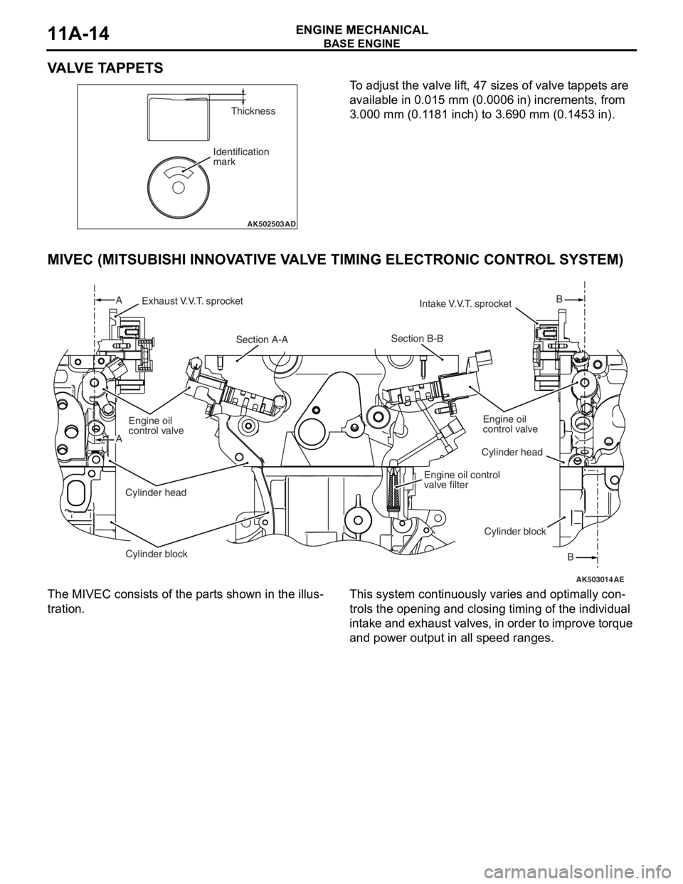
To adjust the valve lift, 47 sizes of valve tappets are
available in 0.015 mm (0.0006 in) increments, from
3.000 mm (0.1181 inch) to 3.690 mm (0.1453 in).
MIVEC (MITSUBISHI INNOVATIVE VALVE TIMING ELECTRONIC CONTROL SYSTEM)
The MIVEC consists of the parts shown in the illus-
tration.
This system continuously varies and optimally con-
trols the opening and closing timing of the individual
intake and exhaust valves, in order to improve torque
and power output in all speed ranges.
AK502503
Identification
markThickness
AD
AK503014
Exhaust V.V.T. sprocket
Section A-ASection B-B
Engine oil control
valve filter
Intake V.V.T. sprocket
Cylinder head
Cylinder blockB
B
Engine oil
control valve
Cylinder head
Cylinder block A
A
AE
Engine oil
control valve
Page 130 of 241
![MITSUBISHI LANCER EVOLUTION X 2008 Workshop Manual IGNITION TIMING AND CONTROL FOR CURRENT CARRYING TIME
MULTIPORT FUEL SYSTEM (MFI)13A-37
2. Spark-advance control and current carrying
time control
.
[During start]
ECM initiates ignition at fixed ign MITSUBISHI LANCER EVOLUTION X 2008 Workshop Manual IGNITION TIMING AND CONTROL FOR CURRENT CARRYING TIME
MULTIPORT FUEL SYSTEM (MFI)13A-37
2. Spark-advance control and current carrying
time control
.
[During start]
ECM initiates ignition at fixed ign](/img/19/57326/w960_57326-129.png)
IGNITION TIMING AND CONTROL FOR CURRENT CARRYING TIME
MULTIPORT FUEL SYSTEM (MFI)13A-37
2. Spark-advance control and current carrying
time control
.
[During start]
ECM initiates ignition at fixed ignition timing (5° BTDC) syn-
chronized with the crankshaft position sensor signal.
.
[During normal operation]
After determining the basic spark-advance based on the intake
air volume and engine speed, ECM makes compensations
based on input from various sensors to control the optimum
spark-advance and current carrying time.
List of main compensations for spark-advance control and current carrying time control
.
[Control for checking ignition timing]
During basic ignition timing set mode for M.U.T.-III actuator test
function, sparking is done with fixed ignition timing (5
° BTDC)
synchronized with crankshaft position sensor signal.
CompensationsContent
Intake air temperature compensationCompensation is made according to intake air
temperature. The higher the intake air temperature
the greater the delay in ignition timing.
Engine coolant temperature compensationCompensation is made according to engine coolant
temperature. The lower the engine coolant
temperature the greater the advance in ignition
timing.
Knocking compensationCompensation is made according to generation of
knocking. The greater the knocking the greater the
delay in ignition timing.
Stable idle compensationCompensation is made according to change in idle
speed. In case engine speed becomes lower than
target speed, ignition timing is advanced.
Delay compensation when changing shiftDuring change of shift, sparking is delayed
compared to normal ignition timing to reduce
engine output torque and absorb the shock of the
shift change.
Battery voltage compensationCompensation is made depending on battery
voltage. The lower the battery voltage the greater
the current carrying time and when battery voltage
is high current carrying time is shortened.
Page 133 of 241
MIVEC (Mitsubishi Innovative Valve Timing Electronic Control System)
MULTIPORT FUEL SYSTEM (MFI)13A-40
MIVEC (Mitsubishi Innovative Valve Timing Electronic
Control System)
M2132023500212
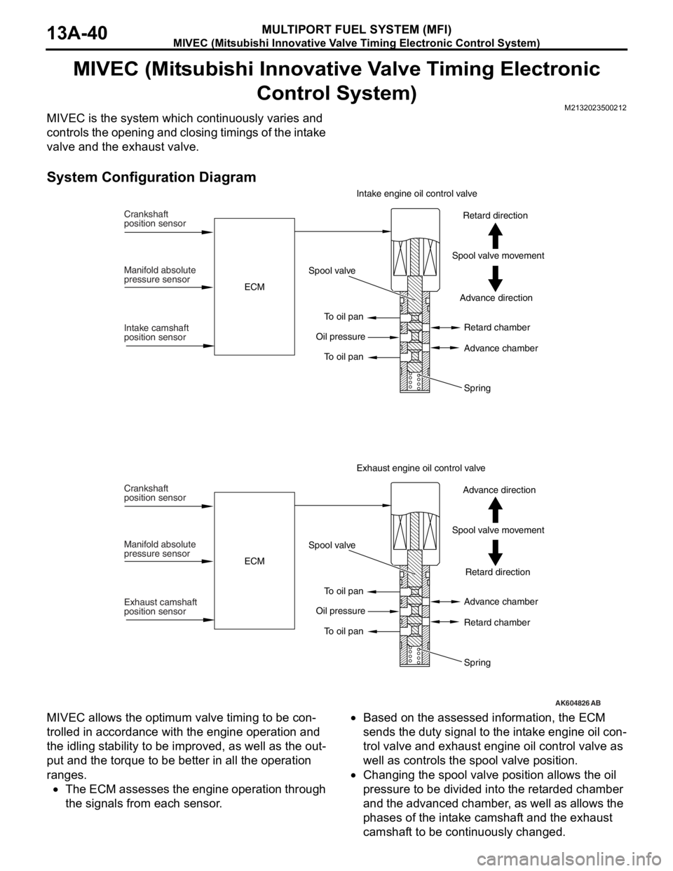
MIVEC is the system which continuously varies and
controls the opening and closing timings of the intake
valve and the exhaust valve.
System Configuration Diagram
MIVEC allows the optimum valve timing to be con-
trolled in accordance with the engine operation and
the idling stability to be improved, as well as the out
-
put and the torque to be better in all the operation
ranges.
•The ECM assesses the engine operation through
the signals from each sensor.
•Based on the assessed information, the ECM
sends the duty signal to the intake engine oil con
-
trol valve and exhaust engine oil control valve as
well as controls the spool valve position.
•Changing the spool valve position allows the oil
pressure to be divided into the retarded chamber
and the advanced chamber, as well as allows the
phases of the intake camshaft and the exhaust
camshaft to be continuously changed.
AK604826AB
Crankshaft
position sensor
Manifold absolute
pressure sensor
Intake camshaft
position sensorECMSpool valve
To oil pan
To oil pan Oil pressureAdvance direction Spool valve movementRetard direction Intake engine oil control valve
Retard chamber
Advance chamber
Spring
Crankshaft
position sensor
Manifold absolute
pressure sensor
Exhaust camshaft
position sensorECMSpool valve
To oil pan
To oil pan Oil pressureRetard direction Spool valve movementAdvance direction Exhaust engine oil control valve
Advance chamber
Retard chamber
Spring
Page 135 of 241
MIVEC (Mitsubishi Innovative Valve Timing Electronic Control System)
MULTIPORT FUEL SYSTEM (MFI)13A-42
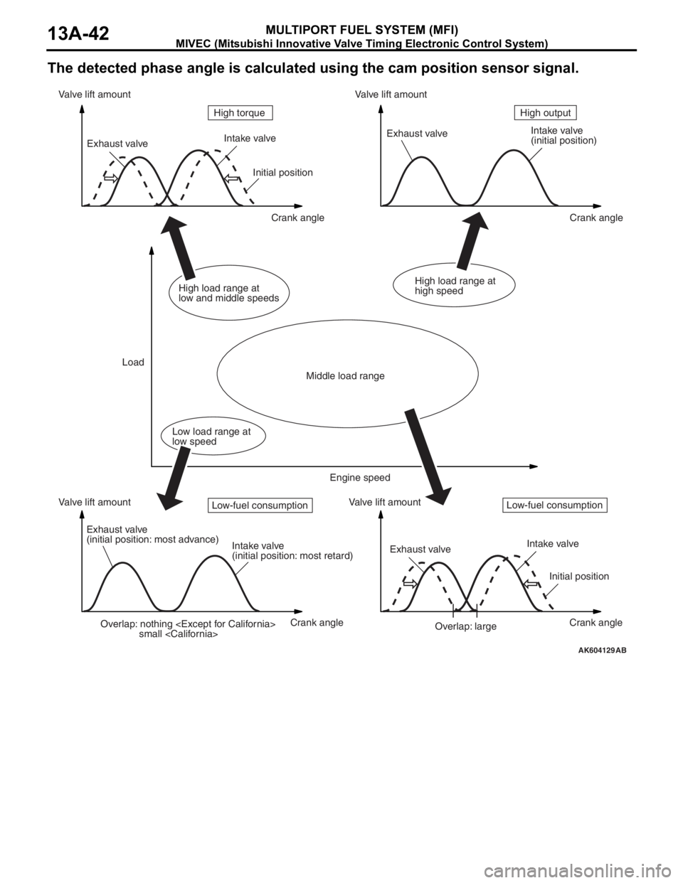
The detected phase angle is calculated using the cam position sensor signal.
AK604129AB
Overlap: nothing
small
(initial position)
Exhaust valve
(initial position: most advance)
Intake valve
(initial position: most retard)Exhaust valveIntake valve
Initial position
Overlap: large Initial position
Crank angle Crank angle
Crank angle Crank angle Valve lift amount Valve lift amountValve lift amount Valve lift amount
LoadHigh output High torque
Middle load range
Low load range at
low speedHigh load range at
low and middle speedsHigh load range at
high speed
Engine speed
Low-fuel consumptionLow-fuel consumption
Page 137 of 241
MIVEC (Mitsubishi Innovative Valve Timing Electronic Control System)
MULTIPORT FUEL SYSTEM (MFI)13A-44
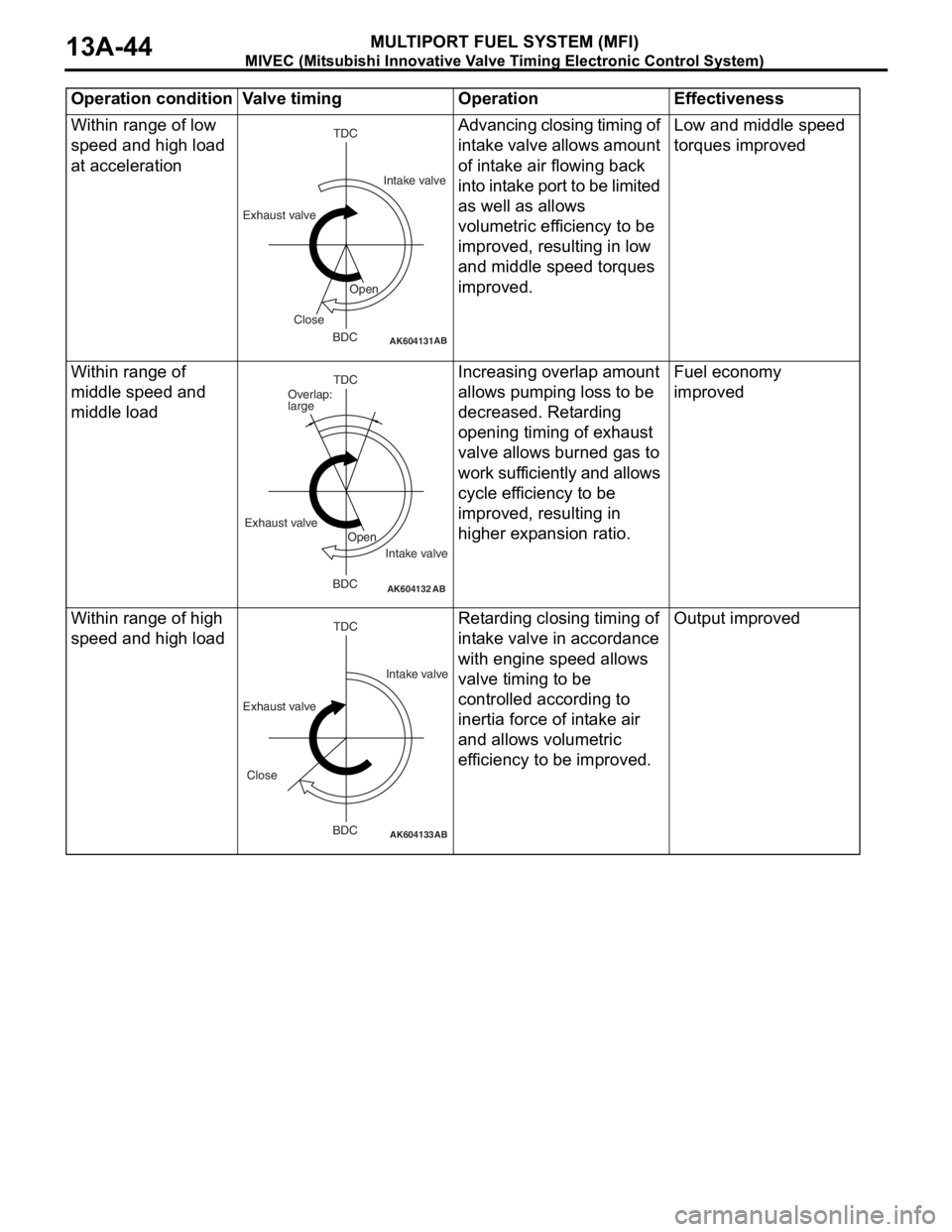
Within range of low
speed and high load
at accelerationAdvancing closing timing of
intake valve allows amount
of intake air flowing back
into intake port to be limited
as well as allows
volumetric efficiency to be
improved, resulting in low
and middle speed torques
improved.Low and middle speed
torques improved
Within range of
middle speed and
middle loadIncreasing overlap amount
allows pumping loss to be
decreased. Retarding
opening timing of exhaust
valve allows burned gas to
work sufficiently and allows
cycle efficiency to be
improved, resulting in
higher expansion ratio.Fuel economy
improved
Within range of high
speed and high loadRetarding closing timing of
intake valve in accordance
with engine speed allows
valve timing to be
controlled according to
inertia force of intake air
and allows volumetric
efficiency to be improved.Output improved
Operation condition Valve timing Operation Effectiveness
AK604131AB
TDC
BDC Exhaust valveIntake valve
Open
Close
AK604132AB
TDC
BDC Exhaust valve
Intake valve Overlap:
large
Open
AK604133
TDC
BDC
AB
Exhaust valveIntake valve
Close
Page 179 of 241
FRONT SEAT ASSEMBLY
TSB Revision
INTERIOR52A-18
REMOVAL SERVICE POINT
.
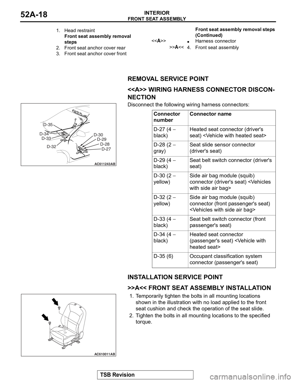
<> WIRING HARNESS CONNECTOR DISCON-
NECTION
Disconnect the following wiring harness connectors:
INSTALLATION SERVICE POINT
.
>>A<< FRONT SEAT ASSEMBLY INSTALLATION
1.Temporarily tighten the bolts in all mounting locations
shown in the illustration with no load applied to the front
seat cushion and check the operation of the seat slide.
2. Tighten the bolts in all mounti ng locations to the specified
torque.
1.Head restraint
Front seat assembly removal
steps
2.Front seat anchor cover rear
3.Front seat anchor cover front
<>•Harness connector
>>A<<4.Front seat assembly
Front seat assembly removal steps
(Continued)
Connector
numberConnector name
D-27 (4 −
black)Heated seat connector (driver's
seat)
D-28 (2 −
gray)Seat slide sensor connector
(driver's seat)
D-29 (4 −
black)Seat belt switch connector (driver's
seat)
D-30 (2 −
yellow)Side air bag module (squib)
connector (driver's seat)
D-32 (2 −
yellow)Side air bag module (squib)
connector (front passenger's seat)
D-33 (4 −
black)Seat belt switch connector (front
passenger's seat)
D-34 (4 −
black)Heated seat connector
(passenger's seat)
D-35 (6)Occupant classification system
connector (passenger's seat)
AC611243
D-30 D-29
D-28D-27
AB
D-32
D-33
D-34 D-35
AC610011AB
Page 237 of 241
STEERING SHAFT AND COLUMN
POWER STEERING37-4
STEERING SHAFT AND COLUMNM2370002000667
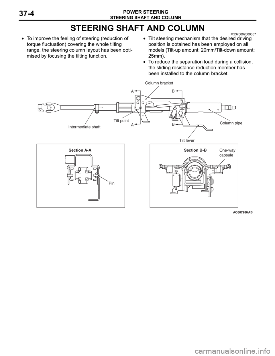
•To improve the feeling of steering (reduction of
torque fluctuation) covering the whole tilting
range, the steering column layout has been opti
-
mised by focusing the tilting function.
•Tilt steering mechanism that the desired driving
position is obtained has been employed on all
models (Tilt-up amount: 20mm/Tilt-down amount:
25mm).
•To reduce the separation load during a collision,
the sliding resistance reduction member has
been installed to the column bracket.
AC607286
A
AB
B
AB
Column bracket
Column pipe Tilt point
Intermediate shaft
Tilt lever
Section B-BOne-way
capsule Section A-A
Pin