display MITSUBISHI LANCER EVOLUTION X 2008 Workshop Manual
[x] Cancel search | Manufacturer: MITSUBISHI, Model Year: 2008, Model line: LANCER EVOLUTION X, Model: MITSUBISHI LANCER EVOLUTION X 2008Pages: 241, PDF Size: 8.26 MB
Page 8 of 241

MITSUBISHI MULTI COMMUNICATION SYSTEM (MMCS)
CHASSIS ELECTRICAL54A-27
MITSUBISHI MULTI COMMUNICATION SYSTEM (MMCS)
GENERAL INFORMATIONM2544800200084
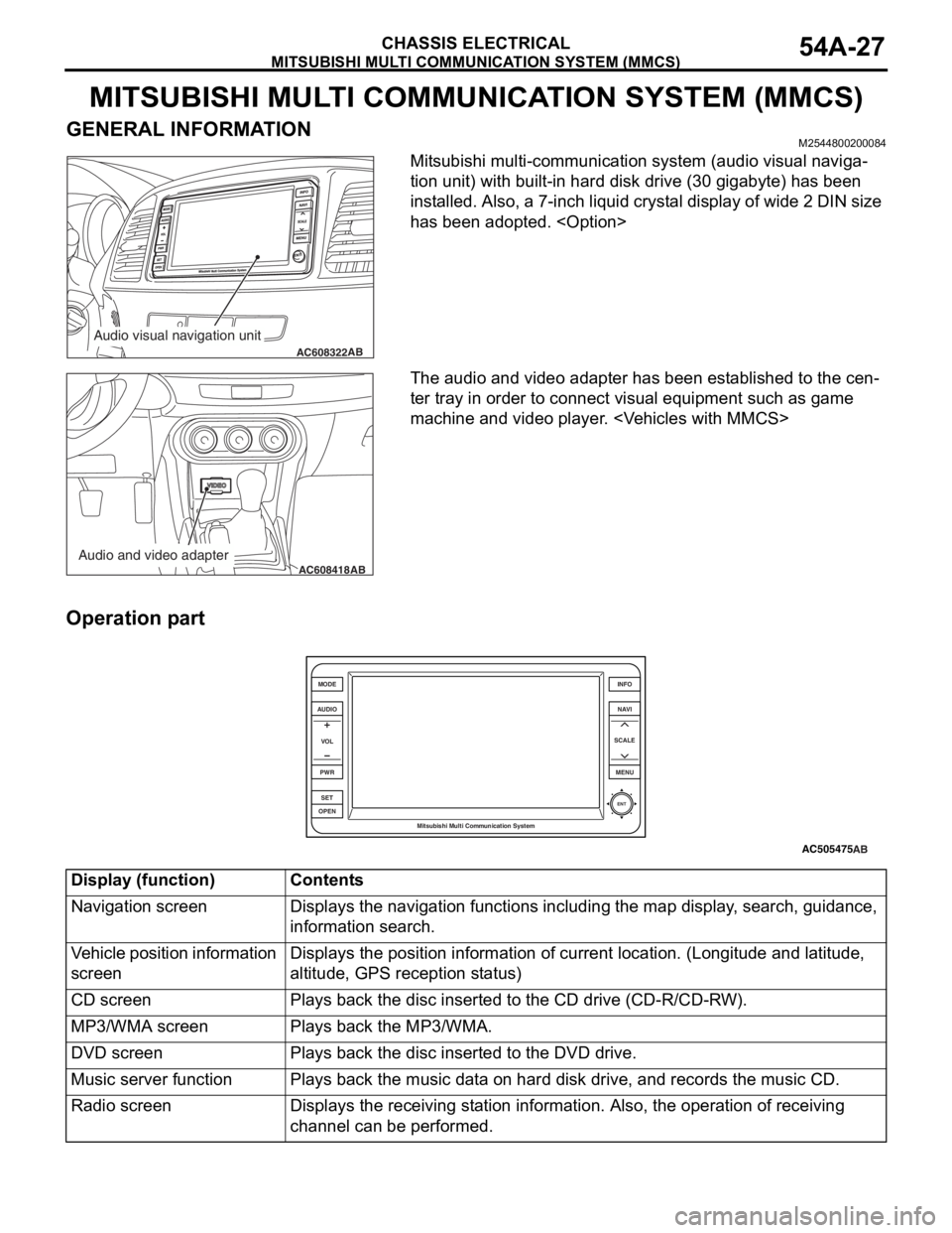
Mitsubishi multi-communication system (audio visual naviga-
tion unit) with built-in hard disk drive (30 gigabyte) has been
installed. Also, a 7-inch liquid crystal display of wide 2 DIN size
has been adopted.
Page 9 of 241

MITSUBISHI MULTI COMMUNICATION SYSTEM (MMCS)
CHASSIS ELECTRICAL54A-28
Navigation function
The storage of very large map data is now possible,
and the following contents have been adopted.
•Map type navigation
•NAVTEQ map database
•Map data stored in hard disc drive
•U.S. English, French, and Spanish are available
to select.
Audio and visual function
The following functions are in addition to the naviga-
tion function:
•Music server function
•DVD drive unit
•FM/AM radio
•MP3/WMA playback function
•Control by steering wheel audio remote comtrol
switch
•Integrated 4-ch power amplifier (MAX: 180 W)
•Correspond to Rockford Fosgate® premium
sound system
•Output of DVD video 5.1 channel data
•Connect with satellite radio tuner
Other function
The following functions are in addition to the naviga-
tion, audio and visual function:
•Clock display
•Connect with hands free unit
•A/C information display
•Outside temperature display
•Trip information display (Average fuel consump-
tion etc.)
•Function customize
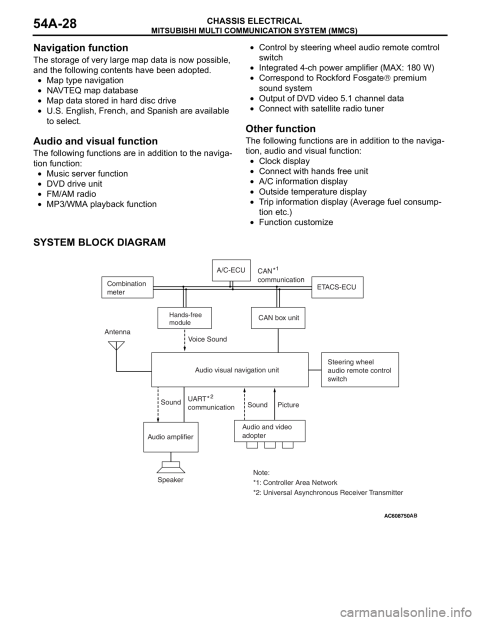
SYSTEM BLOCK DIAGRAM
AC505476
AC608750 ZC3050180000
Audio and video
adopter Antenna
Steering wheel
audio remote control
switch
Speaker
*1: Controller Area Network Note:
*2: Universal Asynchronous Receiver Transmitter UART
communicationn
Sound Sound Voice Sound
Picture
Audio amplifierCAN box unitETACS-ECU Combination
meter
Audio visual navigation unitA/C-ECU
Hands-free
module
CAN
communication
AB
Page 107 of 241

SENSOR
MULTIPORT FUEL SYSTEM (MFI)13A-14
.
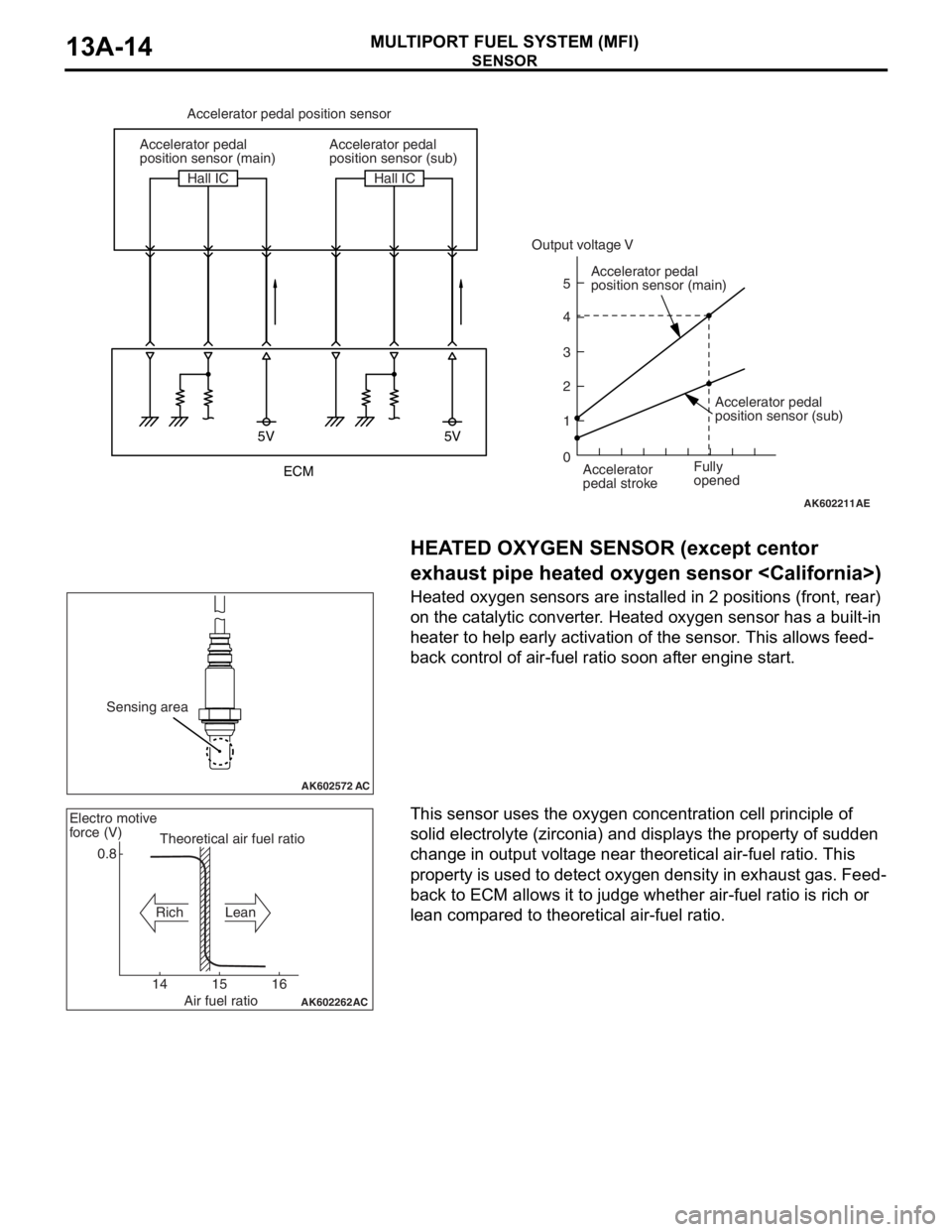
HEATED OXYGEN SENSOR (except centor
exhaust pipe heated oxygen sensor
Heated oxygen sensors are installed in 2 positions (front, rear)
on the catalytic converter. Heated oxygen sensor has a built-in
heater to help early activation of the sensor. This allows feed
-
back control of air-fuel ratio soon after engine start.
.
This sensor uses the oxygen concentration cell principle of
solid electrolyte (zirconia) and displays the property of sudden
change in output voltage near theoretical air-fuel ratio. This
property is used to detect oxygen density in exhaust gas. Feed
-
back to ECM allows it to judge whether air-fuel ratio is rich or
lean compared to theoretical air-fuel ratio.
AK602211
5V 5V
5
4
3
2
1
0
AE
Accelerator pedal position sensor
Accelerator pedal
position sensor (main)
Accelerator pedal
position sensor (main)
Accelerator
pedal stroke Accelerator pedal
position sensor (sub)
Accelerator pedal
position sensor (sub) Hall IC Hall IC
Fully
opened
Output voltage V
ECM
AK602572 AC
Sensing area
AK602262
AC
0.8
14 15 16Theoretical air fuel ratio Electro motive
force (V)
Rich Lean
Air fuel ratio