fuel filter MITSUBISHI LANCER EVOLUTION X 2008 Workshop Manual
[x] Cancel search | Manufacturer: MITSUBISHI, Model Year: 2008, Model line: LANCER EVOLUTION X, Model: MITSUBISHI LANCER EVOLUTION X 2008Pages: 241, PDF Size: 8.26 MB
Page 34 of 241

GENERAL DESCRIPTION
HEATER, AIR CONDITIONING AND VENTILATION55-2
GENERAL DESCRIPTIONM2551001500040
The blower, heater, and evaporator have been inte-
grated with the heater and A/C system to achieve a
greater fan power and noise reduction.
FEATURES
.
ENHANCEMENTS IN COMFORT
•With the adoption of fully-automatic A/C, the out-
side/inside air circulation switching, air outlet, and
outlet air temperature are automatically con
-
trolled according to the ambient temperature,
solar radiation, and passenger compartment tem
-
perature so that the optimum air conditioner is
achieved.
•By the adoption of clean air filter, the air quality
inside the passenger compartment has been
enhanced.
.
ENHANCEMENTS IN OPERATION
PERFORMANCE
•Operability has been enhanced by the adoption
of large triple dial.
•Customise function has been added for the
enhanced convenience.
.
ENHANCEMENTS IN FUEL ECONOMY
•The high efficiency compressor with a 2-step pro-
file oil separator has been installed, thus enhanc-
ing the fuel economy.
•The idle-up speed is controlled in two steps to
secure the air cooling performance during sum
-
mer and to enhance the fuel economy in the sea-
sons with moderate temperature.
•Enhancement of fuel economy by the cooling fan
control depending on the refrigerant pressure and
vehicle speed.
.
ENHANCEMENT IN SAFETY
•A/C system is stopped when the air bags are
deployed.
•Crushable space has been adopted to heater unit
to reduce the risk of passenger injuries in case of
a collision.
.
GLOBAL ENVIRONMENT PROTECTION
•New refrigerant system (HFC134a) has been
adopted.
•By the optimisation of A/C system, the refrigerant
charging amount has been reduced.
•Clean air filter media and its cover are separated
to reduce waste materials.
.
ENHANCEMENTS IN SERVICE QUALITY
•Reduction of refrigerant gas leakage and
enhancement in serviceability by incorporating
condenser and receiver
•Clean air filter is installed to the backside of glove
box to facilitate the filter replacement.
.
ENHANCEMENTS IN RESPONSIBILITY
Reliable information transmission is achieved by
connecting A/C-ECU and each ECU via CAN com
-
munication.
SPECIFICATIONS
ITEMSPECIFICATION
Air conditioning switch typeRotary type
Compressor typeMSC90CAS
Cooling output5.5 kw
Heating output5.7 kw
RefrigerantTy p eR134a (HFC-134a)
Charge quantity g (oz.)480 - 520 (16.9 - 18.3)
Page 92 of 241
GENERAL INFORMATION
FUEL SUPPLY13B-2
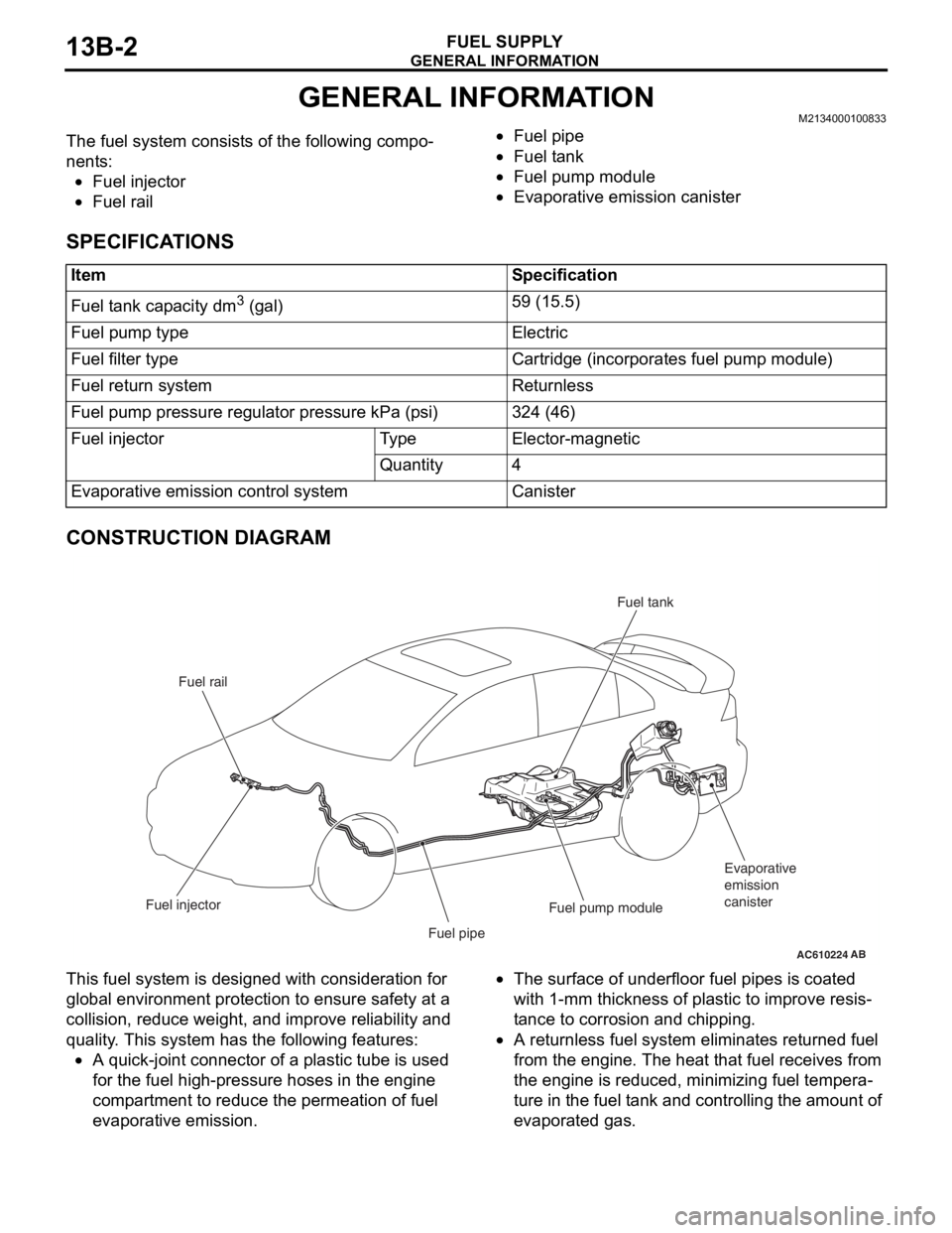
GENERAL INFORMATIONM2134000100833.The fuel system consists of the following compo-
nents:
•Fuel injector
•Fuel rail
•Fuel pipe
•Fuel tank
•Fuel pump module
•Evaporative emission canister
SPECIFICATIONS
CONSTRUCTION DIAGRAM
This fuel system is designed with consideration for
global environment protection to ensure safety at a
collision, reduce weight, and improve reliability and
quality. This system has the following features:
•A quick-joint connector of a plastic tube is used
for the fuel high-pressure hoses in the engine
compartment to reduce the permeation of fuel
evaporative emission.
•The surface of underfloor fuel pipes is coated
with 1-mm thickness of plastic to improve resis
-
tance to corrosion and chipping.
•A returnless fuel system eliminates returned fuel
from the engine. The heat that fuel receives from
the engine is reduced, minimizing fuel tempera
-
ture in the fuel tank and controlling the amount of
evaporated gas.
ItemSpecification
Fuel tank capacity dm3 (gal)59 (15.5)
Fuel pump typeElectric
Fuel filter typeCartridge (incorporates fuel pump module)
Fuel return systemReturnless
Fuel pump pressure regulator pressure kPa (psi)324 (46)
Fuel injectorTy p eElector-magnetic
Quantity4
Evaporative emission control systemCanister
AC610224
Fuel rail
Fuel injector
Fuel pipeFuel pump moduleEvaporative
emission
canister Fuel tank
AB
Page 93 of 241
FUEL TANK
FUEL SUPPLY13B-3
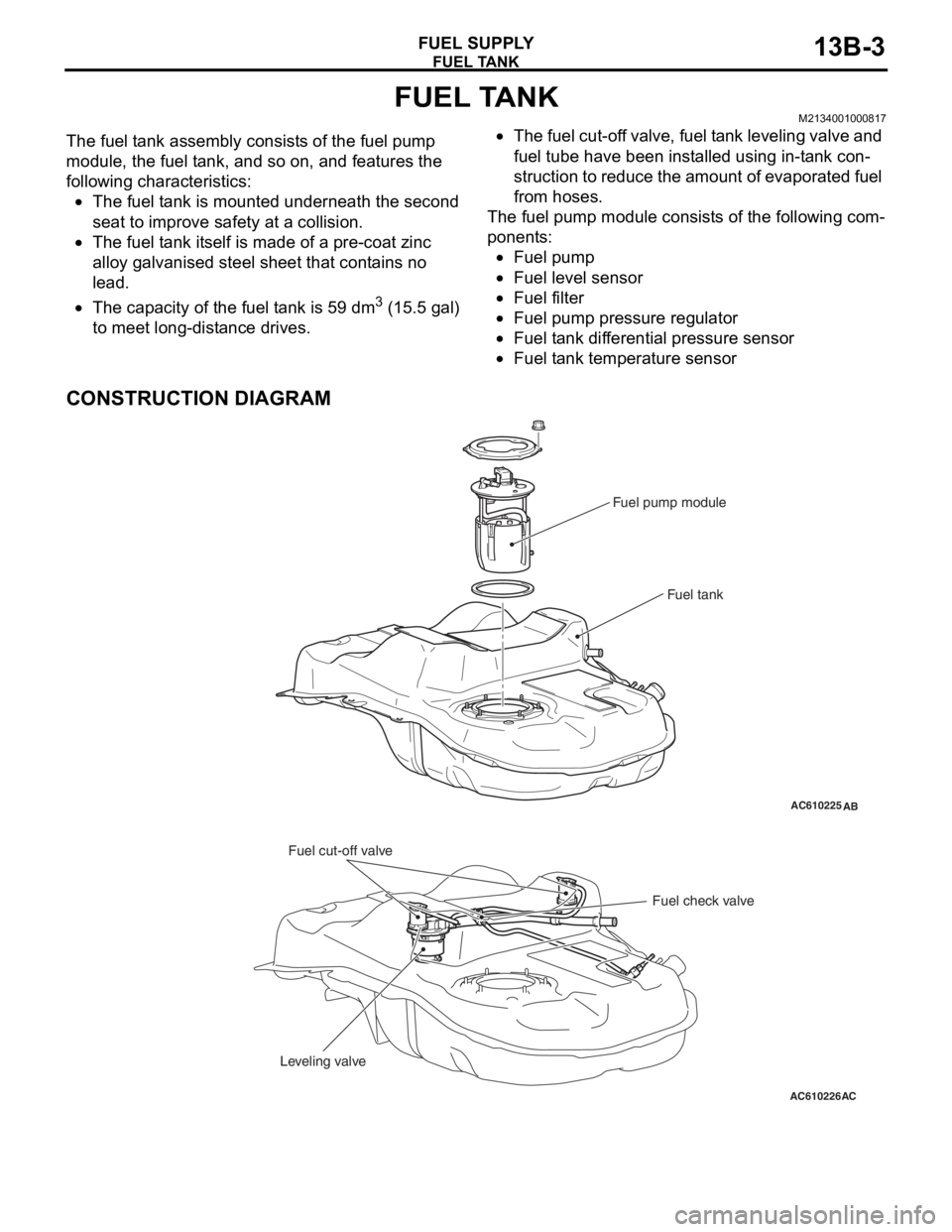
FUEL TANKM2134001000817.The fuel tank assembly consists of the fuel pump
module, the fuel tank, and so on, and features the
following characteristics:
•The fuel tank is mounted underneath the second
seat to improve safety at a collision.
•The fuel tank itself is made of a pre-coat zinc
alloy galvanised steel sheet that contains no
lead.
•The capacity of the fuel tank is 59 dm3 (15.5 gal)
to meet long-distance drives.
•The fuel cut-off valve, fuel tank leveling valve and
fuel tube have been installed using in-tank con
-
struction to reduce the amount of evaporated fuel
from hoses.
The fuel pump module consists of the following com-
ponents:
•Fuel pump
•Fuel level sensor
•Fuel filter
•Fuel pump pressure regulator
•Fuel tank differential pressure sensor
•Fuel tank temperature sensor
CONSTRUCTION DIAGRAM
AC610225AB
Fuel pump module
Fuel tank
AC610226
Fuel cut-off valve
Fuel check valve
Leveling valve
AC
Page 110 of 241
SENSOR
MULTIPORT FUEL SYSTEM (MFI)13A-17
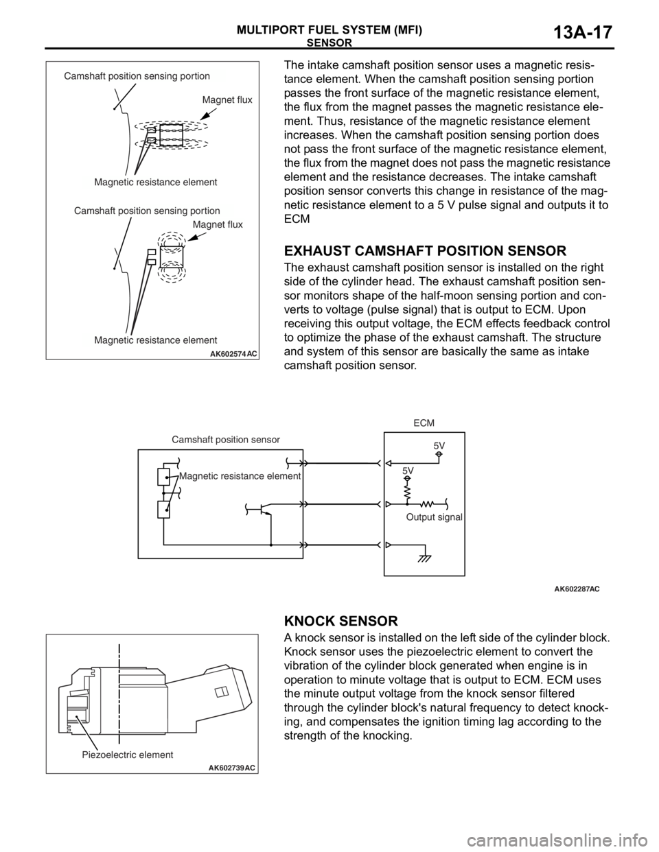
The intake camshaft position sensor uses a magnetic resis-
tance element. When the camshaft position sensing portion
passes the front surface of the magnetic resistance element,
the flux from the magnet passes the magnetic resistance ele
-
ment. Thus, resistance of the magnetic resistance element
increases. When the camshaft position sensing portion does
not pass the front surface of the magnetic resistance element,
the flux from the magnet does not pass the magnetic resistance
element and the resistance decreases. The intake camshaft
position sensor converts this change in resistance of the mag
-
netic resistance element to a 5 V pulse signal and outputs it to
ECM
.
EXHAUST CAMSHAFT POSITION SENSOR
The exhaust camshaft position sensor is installed on the right
side of the cylinder head. The exhaust camshaft position sen
-
sor monitors shape of the half-moon sensing portion and con-
verts to voltage (pulse signal) that is output to ECM. Upon
receiving this output voltage, the ECM effects feedback control
to optimize the phase of the exhaust camshaft. The structure
and system of this sensor are basically the same as intake
camshaft position sensor.
.
.
KNOCK SENSOR
A knock sensor is installed on the left side of the cylinder block.
Knock sensor uses the piezoelectric element to convert the
vibration of the cylinder block generated when engine is in
operation to minute voltage that is output to ECM. ECM uses
the minute output voltage from the knock sensor filtered
through the cylinder block's natural frequency to detect knock
-
ing, and compensates the ignition timing lag according to the
strength of the knocking.
AK602574AC
Camshaft position sensing portion
Camshaft position sensing portionMagnetic resistance element
Magnetic resistance elementMagnet flux
Magnet flux
AK602287
5V5V Camshaft position sensorECM
Output signal Magnetic resistance element
AC
AK602739
Piezoelectric element
AC
Page 116 of 241
ACTUATOR
MULTIPORT FUEL SYSTEM (MFI)13A-23
ACTUATORM2132002000353
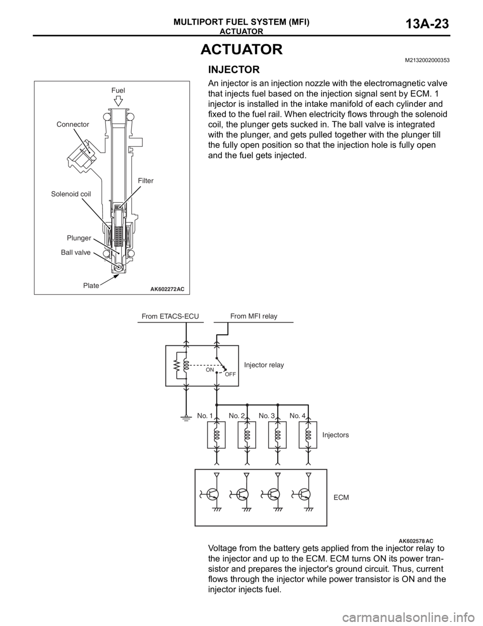
INJECTOR
An injector is an injection nozzle with the electromagnetic valve
that injects fuel based on the injection signal sent by ECM. 1
injector is installed in the intake manifold of each cylinder and
fixed to the fuel rail. When electricity flows through the solenoid
coil, the plunger gets sucked in. The ball valve is integrated
with the plunger, and gets pulled together with the plunger till
the fully open position so that the injection hole is fully open
and the fuel gets injected.
Voltage from the battery gets applied from the injector relay to
the injector and up to the ECM. ECM turns ON its power tran
-
sistor and prepares the injector's ground circuit. Thus, current
flows through the injector while power transistor is ON and the
injector injects fuel.
AK602272AC
Fuel
Plate Ball valvePlunger Solenoid coilConnector
Filter
AK602578
From ETACS-ECUFrom MFI relay
Injector relay
Injectors
OFF ON
ECM
AC
No. 1 No. 2 No. 3 No. 4
Page 120 of 241
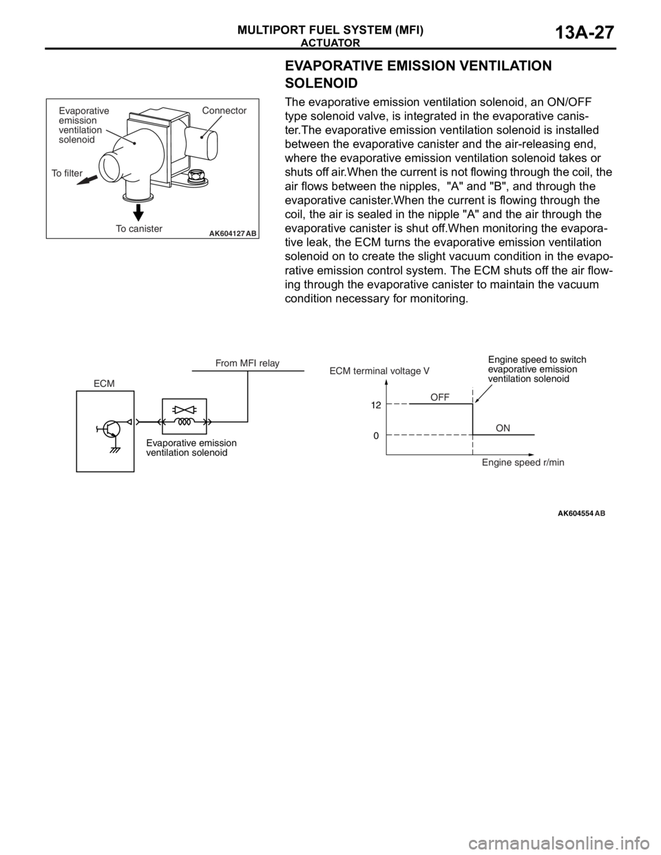
ACTUATOR
MULTIPORT FUEL SYSTEM (MFI)13A-27
EVAPORATIVE EMISSION VENTILATION
SOLENOID
The evaporative emission ventilation solenoid, an ON/OFF
type solenoid valve, is integrated in the evaporative canis
-
ter.The evaporative emission ventilation solenoid is installed
between the evaporative canister and the air-releasing end,
where the evaporative emission ventilation solenoid takes or
shuts off air.When the current is not flowing through the coil, the
air flows between the nipples, "A" and "B", and through the
evaporative canister.When the current is flowing through the
coil, the air is sealed in the nipple "A" and the air through the
evaporative canister is shut off.When monitoring the evapora
-
tive leak, the ECM turns the evaporative emission ventilation
solenoid on to create the slight vacuum condition in the evapo
-
rative emission control system. The ECM shuts off the air flow-
ing through the evaporative canister to maintain the vacuum
condition necessary for monitoring.
AK604127ABTo canisterConnector
Evaporative
emission
ventilation
solenoid
To filter
AK604554
12
0
AB
OFF
ON ECMECM terminal voltage V
Engine speed r/min From MFI relay
Evaporative emission
ventilation solenoidEngine speed to switch
evaporative emission
ventilation solenoid