key MITSUBISHI LANCER EVOLUTION X 2008 Workshop Manual
[x] Cancel search | Manufacturer: MITSUBISHI, Model Year: 2008, Model line: LANCER EVOLUTION X, Model: MITSUBISHI LANCER EVOLUTION X 2008Pages: 241, PDF Size: 8.26 MB
Page 40 of 241

A/C-ECU
HEATER, AIR CONDITIONING AND VENTILATION55-8
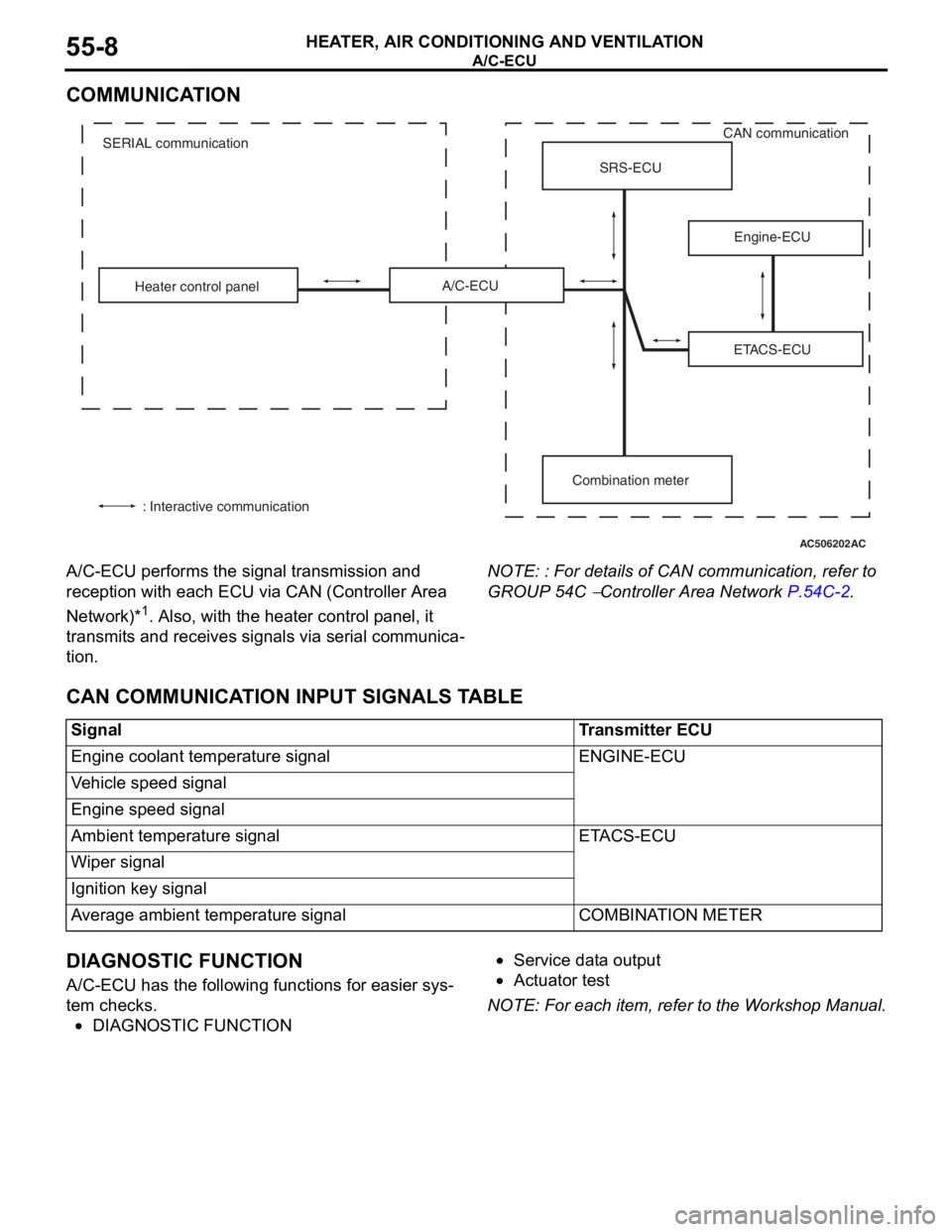
COMMUNICATION
A/C-ECU performs the signal transmission and
reception with each ECU via CAN (Controller Area
Network)*
1. Also, with the heater control panel, it
transmits and receives signals via serial communica
-
tion.
NOTE: : For details of CAN communication, refer to
GROUP 54C
− Controller Area Network P.54C-2.
CAN COMMUNICATION INPUT SIGNALS TABLE
DIAGNOSTIC FUNCTION
A/C-ECU has the following functions for easier sys-
tem checks.
•DIAGNOSTIC FUNCTION
•Service data output
•Actuator test
NOTE: For each item, refer to the Workshop Manual.
AC506202
ETACS-ECU Heater control panelSRS-ECU
Engine-ECU
Combination meter A/C-ECU
: Interactive communicationCAN communication
SERIAL communication
AC
SignalTransmitter ECU
Engine coolant temperature signalENGINE-ECU
Vehicle speed signal
Engine speed signal
Ambient temperature signalETACS-ECU
Wiper signal
Ignition key signal
Average ambient temperature signalCOMBINATION METER
Page 189 of 241

FRONT SEAT BELT
TSB Revision
INTERIOR52A-28
FRONT SEAT BELT
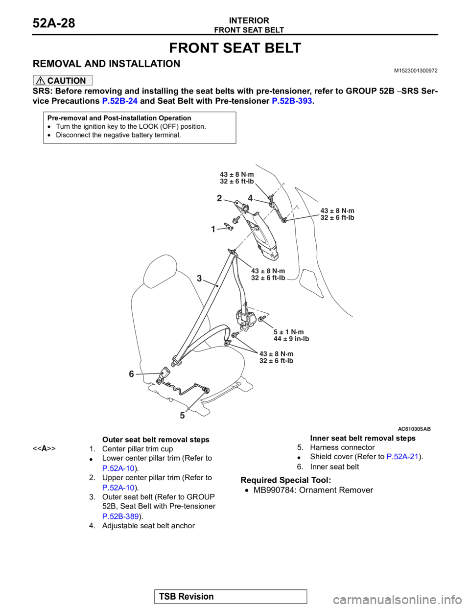
REMOVAL AND INSTALLATIONM1523001300972
CAUTION
SRS: Before removing and installing the seat belts with pre-tensioner, refer to GROUP 52B − SRS Ser-
vice Precautions P.52B-24 and Seat Belt with Pre-tensioner P.52B-393.
Required Special Tool:
•MB990784: Ornament Remover
Pre-removal and Post-installation Operation
•Turn the ignition key to the LOOK (OFF) position.
•Disconnect the negative battery terminal.
AC608130
AC610305
AC608130
1
43 ± 8 N·m
32 ± 6 ft-lb
43 ± 8 N·m
32 ± 6 ft-lb
AB
3
24
5
43 ± 8 N·m
32 ± 6 ft-lb
5 ± 1 N·m
44 ± 9 in-lb
43 ± 8 N·m
32 ± 6 ft-lb
6
Outer seat belt removal steps
<>1.Center pillar trim cup
•Lower center pillar trim (Refer to
P.52A-10).
2.Upper center pillar trim (Refer to
P.52A-10).
3.Outer seat belt (Refer to GROUP
52B, Seat Belt with Pre-tensioner
P.52B-389).
4.Adjustable seat belt anchor
Inner seat belt removal steps
5.Harness connector
•Shield cover (Refer to P.52A-21).
6.Inner seat belt
Page 231 of 241

GENERAL INFORMATION
WHEEL AND TIRE31-2
GENERAL INFORMATIONM2310000100941
•The wheels and tires of the following specifica-
tions have been established.
•Adopt the Tire Pressure Monitoring System
(TPMS).
•Warns driver of low tire pressure by illuminat-
ing the TPMS warning light on the combina-
tion meter.
•Warns driver of TPMS probrems by flashing*
the TPMS warning light on the combination
meter.
NOTE: *: Change to continuous illumination
after flashing for about 1 minute.
SPECIFICATIONS
.
ROAD WHEEL AND TIRE
SPARE WHEEL AND TIRE
NOTE: .
•The * mark indicates optional item.
•PCD indicates the pitch circle diameter of the wheel installation holes.
TIRE PRESSURE MONITORING SYSTEM (TPMS)M2310000200067
Refer to GROUP 42B − Keyless Operation System
(KOS)
P.42B-20 or GROUP 42C − Wireless Control
Module (WCM) P.42C-9.
ItemDEESGT S
TPMS warning
pressure kPa
(psi)Warning ON174 (25.2) or less174 (25.2) or less174 (25.2) or less
Warning OFF189 (27.4) or less189 (27.4) or less189 (27.4) or less
WheelTy p eSteel type or
Aluminium type
*
Aluminum typeAluminum type
Size16 × 6 1/2JJ16 × 6 1/2JJ18 × 7JJ
Amount of wheel
offset mm (in)46 (1.8)46 (1.8)46 (1.8)
PCD mm (in)114.3 (4.50)114.3 (4.50)114.3 (4.50)
TireSizeP205/60R16 91HP205/60R16 91HP215/45R18 89V
ItemSpecification
WheelTy p eSteel type
Size16 × 4T
Amount of wheel offset mm (in)40 (1.6)
PCD mm (in)114.3 (4.50)
TireSizeT125/70D16 96M