roof MITSUBISHI LANCER EVOLUTION X 2008 Workshop Manual
[x] Cancel search | Manufacturer: MITSUBISHI, Model Year: 2008, Model line: LANCER EVOLUTION X, Model: MITSUBISHI LANCER EVOLUTION X 2008Pages: 241, PDF Size: 8.26 MB
Page 6 of 241
SPEAKER
CHASSIS ELECTRICAL54A-25
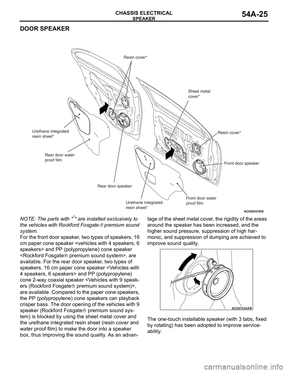
DOOR SPEAKER
NOTE: The parts with "*" are installed exclusively to
the vehicles with Rockford Fosgate
® premium sound
system.
For the front door speaker, two types of speakers, 16
cm paper cone speaker
available. For the rear door speaker, two types of
speakers, 16 cm paper cone speaker
cone 2-way coaxial speaker
ers (Rockford Fosgate® premium sound system)>,
are available. Compared to the paper cone speakers,
the PP (polypropylene) cone speakers can playback
crisper bass. The door opening of the vehicles with 9
speaker (Rockford Fosgate
® premium sound sys-
tem) is blocked by using the sheet metal cover and
the urethane integrated resin sheet (resin cover and
water proof film) to make the door into a speaker
box, thus improving the sound quality. As an advan
-
tage of the sheet metal cover, the rigidity of the areas
around the speaker has been increased, and the
higher sound pressure, suppression of high har
-
monic, and suppression of dumping are achieved to
improve sound quality.
The one-touch installable speaker (with 3 tabs, fixed
by rotating) has been adopted to improve service
-
ability.
AC608347
Front door speaker
Rear door speaker
Sheet metal
cover*
Resin cover*
Resin cover*
AB
Front door water
proof film
Rear door water
proof film
Urethane integrated
resin sheet*
Urethane integrated
resin sheet*
AC507245AB
Page 11 of 241
AUDIO SYSTEM
TSB Revision
CIRCUIT DIAGRAMS90-169
FUSIBLE
LINK37
ACC
RELAY 2ROOF ANTENNA
ANTENNA
AMPLIFIER
ANTENNA FEEDER CABLE
ETACS-ECU IGNITION
SWITCH (ACC)
REFER TO
POWER
DISTRIBUTION
SYSTEM
WIRE COLOR CODE
B : BLACK LG : LIGHT GREEN G : GREEN L : BLUE W : WHITE Y : YELLOW SB : SKY BLUE
BR : BROWN O : ORANGE GR : GRAY R : RED P : PINK V : VIOLET PU : PURPLE COMBINATION METER
A/C
CONTROL
PANEL
JOINT
CONNECTOR
(3)
Page 17 of 241
AUDIO SYSTEM
TSB Revision
CIRCUIT DIAGRAMS90-175
ACC
RELAY 2 FUSIBLE
LINK
37
ROOF ANTENNA
ANTENNA AMPLIFIER
ANTENNA FEEDER CABLE ANTENNA FEEDER CABLE
ETACS-
ECU
RADIO AND CD PLAYER OR CD CHANGER
SWITCH (ACC)
SATELLITE
RADIO TUNER
WIRE COLOR CODE
B : BLACK LG : LIGHT GREEN G : GREEN L : BLUE W : WHITE Y : YELLOW SB : SKY BLUE
BR : BROWN O : ORANGE GR : GRAY R : RED P : PINK V : VIOLET PU : PURPLEJOINT
CONNECTOR
(1)
REFER TO
POWER
DISTRIBUTION
SYSTEM
Page 28 of 241
MITSUBISHI MULTI COMMUNICATION SYSTEM (MMCS)
TSB Revision
CIRCUIT DIAGRAMS90-187
ACC
RELAY 2 FUSIBLE
LINK
37
ROOF ANTENNA
ANTENNA AMPLIFIER
ANTENNA FEEDER CABLE ANTENNA FEEDER CABLE
ETACS-
ECU
TUNER> IGNITION
SWITCH (ACC)
SATELLITE
RADIO TUNER
WIRE COLOR CODE
B : BLACK LG : LIGHT GREEN G : GREEN L : BLUE W : WHITE Y : YELLOW SB : SKY BLUE
BR : BROWN O : ORANGE GR : GRAY R : RED P : PINK V : VIOLET PU : PURPLE
REFER TO
POWER
DISTRIBUTION
SYSTEM
JOINT
CONNECTOR (3)
Page 46 of 241

GENERAL DESCRIPTION
ENGINE MECHANICAL11A-2
GENERAL DESCRIPTIONM2112000101162
This model is equipped with a newly developed 4B11
engine. It is a 4-cylinder, double overhead camshaft
(DOHC) engine with a 2.0-L cylinder displacement.
This engine has adopted the following features:
•MIVEC (MITSUBISHI INNOVATIVE VALVE TIM-
ING ELECTRONIC CONTROL SYSTEM) for
both the intake and exhaust valves
•Cylinder block made of an aluminum alloy
•Valve train with direct-acting valve tappets
•Silent timing chain
MAIN SPECIFICATIONS
DescriptionsSpecifications
Engine type4B11
Bore × stroke mm (in)86 (3.4) × 86 (3.4)
Total displacement cm3 (cu in)1,998 (121.9)
Combustion chamberPent-roof type
Number of cylinders4
Valve mechanismTy p eDOHC
Intake valve8
Exhaust valve8
Compression ratio10.0
Va l v e t i m i n gIntake valveOpens (BTDC)3° − 28°
0° − 25°
Closes (ABDC)45° − 20°
48° − 23°
Exhaust valveOpens (BBDC)41° − 21°
44° − 24°
Closes (ATDC)3° − 23°
0° − 20°
Maximum output kW/r/min (HP/r/min)107/6,000 (143/6,000)
113/6,000 (152/6,000)
Maximum torque N⋅m/r/min (lbs-ft/r/min)194/4,250 (143/4,250)
198/4,250 (146/4,250)
Fuel injection system typeElectronic control MPI
Ignition system typeElectronic spark-advance control type (4-coil
type)
Generator typeAlternating current system (with built-in IC
regulator)
Starter motor typeReduction drive type
Page 47 of 241
BASE ENGINE
ENGINE MECHANICAL11A-3
BASE ENGINEM2112001001050
CYLINDER HEAD
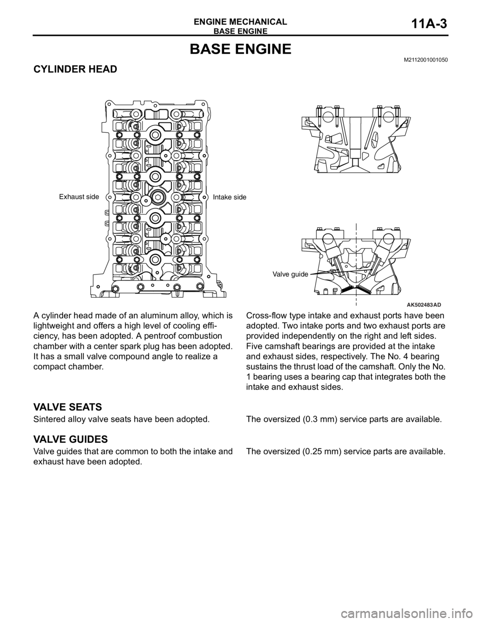
A cylinder head made of an aluminum alloy, which is
lightweight and offers a high level of cooling effi
-
ciency, has been adopted. A pentroof combustion
chamber with a center spark plug has been adopted.
It has a small valve compound angle to realize a
compact chamber.
Cross-flow type intake and exhaust ports have been
adopted. Two intake ports and two exhaust ports are
provided independently on the right and left sides.
Five camshaft bearings are provided at the intake
and exhaust sides, respectively. The No. 4 bearing
sustains the thrust load of the camshaft. Only the No.
1 bearing uses a bearing cap that integrates both the
intake and exhaust sides.
VA LV E S E AT S
Sintered alloy valve seats have been adopted.The oversized (0.3 mm) service parts are available.
VA LV E G U I D E S
Valve guides that are common to both the intake and
exhaust have been adopted.The oversized (0.25 mm) service parts are available.
AK502483
Valve guide
AD
Exhaust side
Intake side
Page 176 of 241
HEADLINING
TSB Revision
INTERIOR52A-15
HEADLINING
REMOVAL AND INSTALLATIONM1521001400973
Pre-removal and Post-installation Operation
•Removal and Installation of Front Pillar Trim, Upper Cen-
ter Pillar Trim, Rear Pillar Trim (Refer to P.52A-10).
•Removal and Installation of Instrument Under Cover
(Refer to
P.52A-6).
AC609656
2
6
1
1
1
1
3 4
45
5
7
7
8
8
9 8
9 10
10
8
AB
A
A
Section A – AClip
Claw
8
3
Note
(1) : Clip positions
(2) : Claw positions
Page 177 of 241

HEADLINING
TSB Revision
INTERIOR52A-16
Required Special Tool:
•MB990784: Ornament Remover
REMOVAL SERVICE POINTS
.
<> SUN VISOR HOLDER REMOVAL
Insert the special tool MB990784 into side claws of the sun
visor holder through the both sides of the sun visor holder to
remove the hinges.
.
<> HEADLINING ASSEMBLY REMOVAL
To remove the clip, insert a vinyl cord into a clearance between
the clip and the headlining, and pass it around the clip. Then,
pull out the clip downwards while pulling the vinyl cord.
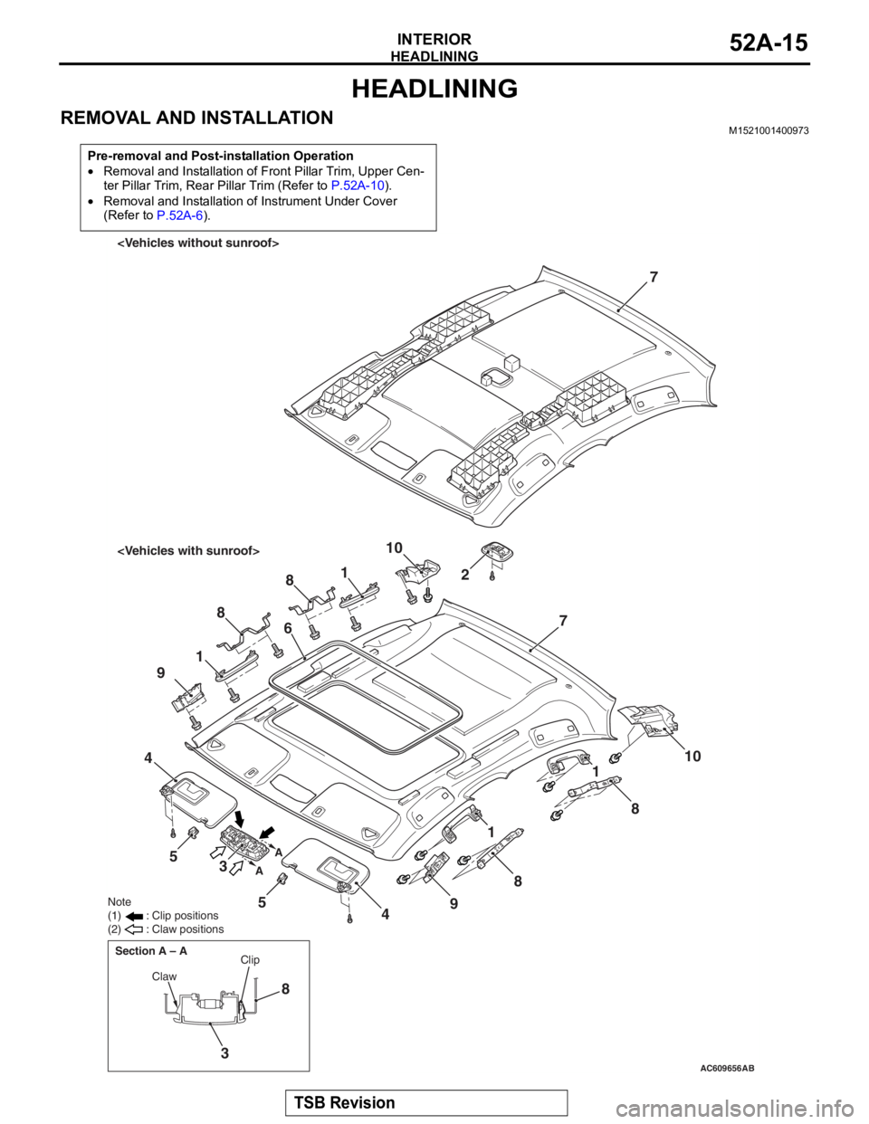
Removal steps
1.Assist grip
2.Rear dome light assembly
3.Front dome light
4.Sun visor assembly
<>5.Sun visor holder
6.Sunroof lid inner weather strip rear
<>7.Headlining
8.Assist grip bracket
9.Front side roof energy absorption box
10.Rear side roof energy absorption box
Removal steps (Continued)
AC005512
MB990784
MB990784
Sun visor holder
AF
AC600751AD
Clip
Headlining Vinyl cord