Dash panel MITSUBISHI LANCER IX 2006 Service Manual
[x] Cancel search | Manufacturer: MITSUBISHI, Model Year: 2006, Model line: LANCER IX, Model: MITSUBISHI LANCER IX 2006Pages: 800, PDF Size: 45.03 MB
Page 411 of 800

80-1
GROUP 80
CONFIGURATION
DIAGRAMS
CONTENTS
OVERALL CONFIGURATION DIAGRAM
OVERALL WIRING DIAGRAM
OVERALL WIRING DIAGRAM
OVERALL WIRING DIAGRAM
OVERALL WIRING DIAGRAM
ENGINE COMPARTMENT
ENGINE COMPARTMENT
ENGINE COMPARTMENT
ENGINE AND TRANSMISSION
ENGINE AND TRANSMISSION
<4G1-MPI (LHD)> . . . . . . . . . . . . . . . . . . . . 80-10
ENGINE AND TRANSMISSION
<4G1-MPI (RHD)> . . . . . . . . . . . . . . . . . . . 80-14
ENGINE AND TRANSMISSION
<4G6-MPI (LHD)> . . . . . . . . . . . . . . . . . . . . 80-18
ENGINE AND TRANSMISSION
<4G6-MPI (RHD)> . . . . . . . . . . . . . . . . . . . 80-22
DASH PANEL
DASH PANEL
DASH PANEL
FLOOR AND ROOF
FLOOR AND ROOF
FLOOR AND ROOF
FLOOR AND ROOF
FLOOR AND ROOF
DOOR
DOOR
DOOR
TRUNK (LUGGAGE COMPARTMENT)
TRUNK (LUGGAGE COMPARTMENT)
TRUNK (LUGGAGE COMPARTMENT)
TAILGATE
TAILGATE
TAILGATE
Page 436 of 800

DASH PANEL
CONFIGURATION DIAGRAMS80-26
DASH PANEL
DASH PANEL
AC502051
16
C-38C-06
C-05
C-02
C-01
C-34
C-32 C-31
C-29
C-40
C-27
C-25 C-24C-22
C-21
Connector colour
code
B : Black
BR : Brown
G : Green
GR : Grey
L : Blue
None : Milk white
O : Orange
R : Red
V : Violet
Y : Yellow
Connector
symbol
-01
thru
-40
C
C-04
C-03
C-36
C-33
C-35
6
J/B
AB
C-01(6)Fog lamp switch
C-02(1)Spare connector (for front fog lamp
switch)
C-03(22-B)J/C (5)
C-04(21)Combination meter
C-05(4)Stop lamp switch
C-06(21-L)Combination meter
C-08(1-B)Spare connector (for audio)
C-09(14)Spare connector (for audio)
C-10(1)Instrument panel wiring harness and
antenna feeder cable combination
C-11(16-B)Diagnosis connector
C-12(33)J/C (6)
C-13(25)Instrument panel wiring harness and
control wiring harness combination
C-14(10-GR)Instrument panel wiring harness and
control wiring harness combination
C-15(22-L)Instrument panel wiring harness and
control wiring harness combination
C-19(12)Diagnosis connector
C-21(3)Front wiring harness (LH) and instrument
panel wiring har ness combination
Page 437 of 800
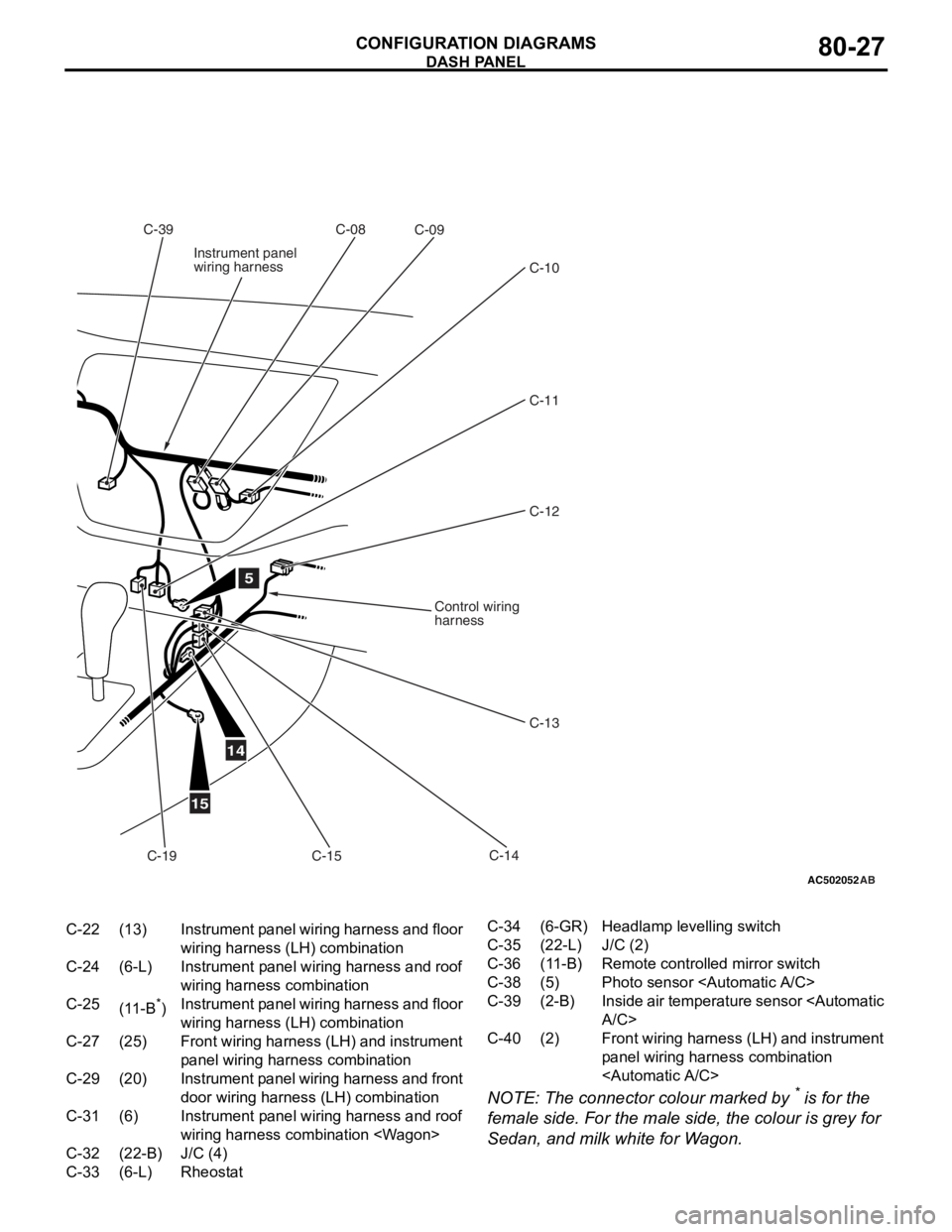
AC502052AB
5
14
15
C-08C-39C-09
C-11C-12
C-10
C-14
C-15
C-13
Instrument panel
wiring harness
Control wiring
harness
C-19
C-22(13)Instrument panel wiring harness and floor
wiring harness (LH) combination
C-24(6-L)Instrument panel wiring harness and roof
wiring harness combination
C-25(11-B*)Instrument panel wiring harness and floor
wiring harness (LH) combination
C-27(25)Front wiring harness (LH) and instrument
panel wiring harn ess combination
C-29(20)Instrument panel wiring harness and front
door wiring harness (LH) combination
C-31(6)Instrument panel wiring harness and roof
wiring harness combination
C-32(22-B)J/C (4)
C-33(6-L)Rheostat
C-34(6-GR)Headlamp levelling switch
C-35(22-L)J/C (2)
C-36(11-B)Remote controlled mirror switch
C-38(5)Photo sensor
C-39(2-B)Inside air temperature sensor
C-40(2)Front wiring harness (LH) and instrument
panel wiring harness combination
DASH P ANEL
CONF IGURA TION D I A G RA MS80-27
NOTE: The conn ecto r colour marked by * is fo r the
female side. F
o
r the male
side, the
colour is grey for
Se
dan, a
nd milk white f
o
r W
a
g
on.
Page 438 of 800
DASH PANEL
CONFIGURATION DIAGRAMS80-28
DASH PANEL
AC502053
C-140C-102
C-103
C-141
C-101
C-132
C-139
C-148
C-130
C-146C-145
Y
4
Connector
symbol
-101
thru
-149
C
Connector colour
code
B : Black
BR : Brown
G : Green
GR : Grey
L : Blue
None : Milk white
O : Orange
R : Red
V : Violet
Y : Yellow
Instrument panel
wiring harness
C-131
C-133
C-147
AB
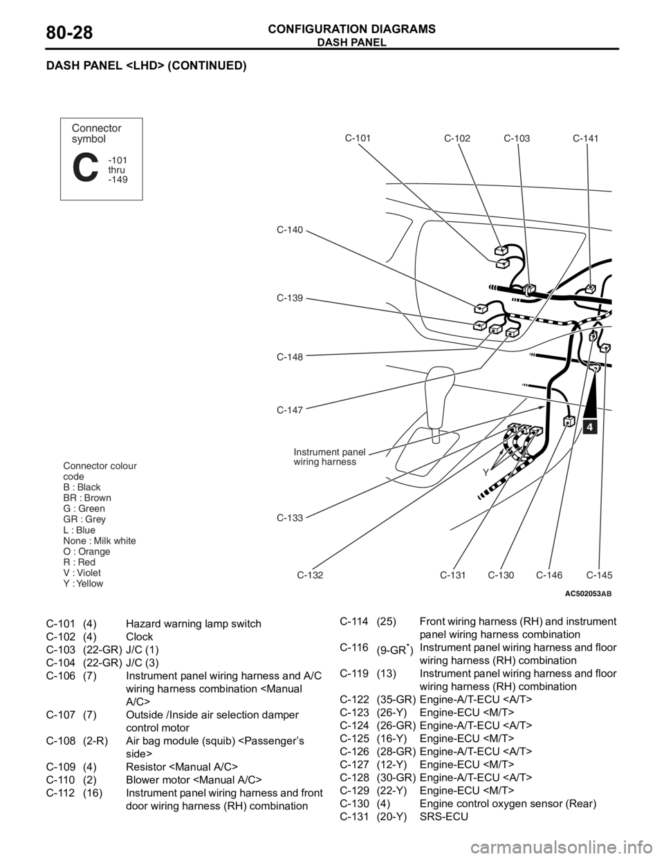
C-101(4)Hazard warning lamp switch
C-102(4)Clock
C-103(22-GR)J/C (1)
C-104(22-GR)J/C (3)
C-106(7)Instrument panel wiring harness and A/C
wiring harness combination
C-107(7)Outside /Inside air selection damper
control motor
C-108(2-R)Air bag module (squib)
C-109(4)Resistor
C-110(2)Blower motor
C-112(16)Instrument panel wiring harness and front
door wiring harness (RH) combination
C-114(25)Front wiring harness (RH) and instrument
panel wiring har
ness combination
C-116(9-GR*)Instrument panel wiring harness and floor
wiring harness (RH) combination
C-119(13)Instrument panel wiring harness and floor
wiring harness (RH) combination
C-122(35-GR)Engine-A/T-ECU
C-123(26-Y)Engine-ECU
C-124(26-GR)Engine-A/T-ECU
C-125(16-Y)Engine-ECU
C-126(28-GR)Engine-A/T-ECU
C-127(12-Y)Engine-ECU
C-128(30-GR)Engine-A/T-ECU
C-129(22-Y)Engine-ECU
C-130(4)Engine control oxygen sensor (Rear)
C-131(20-Y)SRS-ECU
Page 439 of 800

AC502054
C-142
AB
C-104C-106
C-143
C-107
C-109
C-149
C-110
C-144
C-112
C-114
C-116
C-119
C-126
C-127
C-128
C-129
2
C-108
C-124
C-125C-122
C-123
3
Control wiring
harness
A/C wiring
harness
Antenna
feeder
cable
C-132(28-Y)SRS-ECU
C-133(20-Y)SRS-ECU
C-139(16-B)A/C-ECU or heater control unit
C-140(6)Blower switch
C-141(6)Air mixing door control motor and
potentiometer
C-142(2)Air thermo sensor
C-143(13)Instrument panel wiring harness and A/C
wiring harness combination
C-144(6)Blower motor
C-145(6)Mode selection damper control motor and
potentiometer
C-146(2)Heater water temperature sensor
C-147(20-B)A/C-ECU
C-148(16-B)A/C-ECU
C-149(2)Instrument panel wiring harness and
tweeter wiring harn
ess combination
DASH P ANEL
CONF IGURA TION D I A G RA MS80-29
NOTE: The conn ecto r colour marked by * is fo r the
female side.F
o
r the male
sid
e
, the
colour is grey for
Se
dan, a
nd milk white f
o
r W
a
g
on.
Page 440 of 800

DASH PANEL
CONFIGURATION DIAGRAMS80-30
DASH PANEL
AC301179
Connector
symbol
-201
thru
-227
C
AB
STEERING COLUMN
C-207
C-206 C-201
C-202
C-203C-203
C-204
C-205 Instrument panel
wiring harness
Clock spring
Y
C-201(6)Ignition switch
C-202(7)Key reminder switch
C-203(10)Column switch
C-204(6)Clock spring
C-205(4-Y)Clock spring
C-206(1)Horn switch
C-207(2)Air bag module (squib)
C-208(13)Instrument panel wiring harness and J/B
combination
C-209(14)Instrument panel wiring harness and J/B
combination
C-210(6)Instrument panel wiring harness and J/B
combination
C-211(1-B)Instrument panel wiring harness and J/B
combination
C-212(28)Instrument panel wiring harness and J/B
combination
Page 442 of 800

DASH PANEL
CONFIGURATION DIAGRAMS80-32
DASH PANEL
M1801000601772
AC502055
C-10C-09 C-08
Control wiring
harness
C-37
C-16 C-17 C-18
C-11
C-19
Y
4
Connector
symbol
-01
thru
-39
C
Connector colour
code
B : Black
BR : Brown
G : Green
GR : Grey
L : Blue
None : Milk white
O : Orange
R : Red
V : Violet
Y : Yellow
Instrument panel
wiring harness
C-38
AB
C-01(6)Fog lamp switch
C-02(1)Spare connector (for front fog lamp
switch)
C-04(21)Combination meter
C-05(4)Stop lamp switch
C-06(21-L)Combination meter
C-07(22-GR)J/C (3)
C-08(1-B)Spare connector (for audio)
C-09(14)Spare connector (for audio)
C-10(1)Instrument panel wiring harness and
antenna feeder cable combination
C-11(16-B)Diagnosis connector
C-16(20-Y)SRS-ECU
C-17(28-Y)SRS-ECU
C-18(20-Y)SRS-ECU
C-19(12)Diagnosis connector
C-20(2)No connection
Page 443 of 800
AC502056
C-39
AB
C-04 C-07 C-06 C-05 C-02 C-01J/B C-34
C-33
C-31
C-30
C-28
C-26
C-23 C-24
C-20 C-32
C-35
2
C-36
6
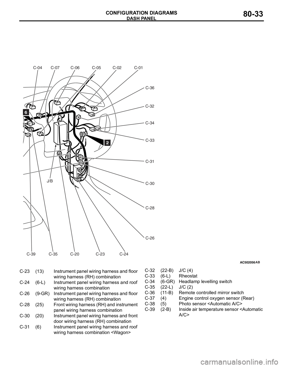
C-23(13)Instrument panel wiring harness and floor
wiring harness ( RH) combination
C-24(6-L)Instrument panel wiring harness and roof
wiring harness combination
C-26(9-GR)Instrument panel wiring harness and floor
wiring harness (RH) combination
C-28(25)Front wiring harness (RH) and instrument
panel wiring harn ess combination
C-30(20)Instrument panel wiring harness and front
door wiring harness (RH) combination
C-31(6)Instrument panel wiring harness and roof
wiring harness combination
C-32(22-B)J/C (4)
C-33(6-L)Rheostat
C-34(6-GR)Headlamp levelling switch
C-35(22-L)J/C (2)
C-36(11-B)Remote controlled mirror switch
C-37(4)Engine control oxygen sensor (Rear)
C-38(5)Photo sensor
C-39(2-B)Inside air temperature sensor
DASH P ANEL
CONF IGURA TION D I A G RA MS80-33
Page 444 of 800

DASH PANEL
CONFIGURATION DIAGRAMS80-34
DASH PANEL
AC502057
Y
16
C-105
C-106
C-143
C-107
C-108
A/C wiring
harness
C-109
C-149
C-110
C-144
C-111
C-113
C-115
C-117
Instrument panel
wiring harness
Control wiring
harness
C-118 C-120
C-121C-128
C-129 C-126
C-127C-124
C-125
C-122
C-123
Connector colour
code
B : Black
BR : Brown
G : Green
GR : Grey
L : Blue
None : Milk white
O : Orange
R : Red
V : Violet
Y : Yellow
3
Connector
symbol
-101
thru
-149
C
Antenna
feeder
cable
AB
C-142
C-101(4)Hazard warning lamp switch
C-102(4)Clock
C-103(22-GR)J/C (1)
C-105(13)J/C (5)
C-106(7)Instrument panel wiring harness and A/C
wiring harness combination
C-107(7)Outside /Inside air selection damper
control motor
C-108(2-R)Air bag module (squib)
C-109(4)Resistor <
C-110(2)Blower motor
C-111(12)Front wiring harness (LH) and control
wiring harness combination
C-113(16)Instrument panel wiring harness and front
door wiring harness (LH) combination
C-115(25)Front wiring harness (LH) and instrument
panel wiring harn
ess combination
C-117(11-B*)Instrument panel wiring harness and floor
wiring harness (LH) combination
C-118(6-L)Instrument panel wiring harness and floor
wiring harness (LH) combination
C-120(13)Instrument panel wiring harness and floor
wiring harness (LH) combination
C-121(3)Front wiring harness (LH) and instrument
panel wiring harness combination
C-122(35-GR)Engine-A/T-ECU
C-123(26-Y)Engine-ECU
C-124(26-GR)Engine-A/T-ECU
C-125(16-Y)Engine-ECU
C-126(28-GR)Engine-A/T-ECU
C-127(12-Y)Engine-ECU
C-128(30-GR)Engine-A/T-ECU
C-129(22-Y)Engine-ECU
C-134(33)J/C (6)
C-135(22-L)Instrument panel wiring harness and
control wiring harness combination
Page 445 of 800

AC502058AB
5
14
15
C-103C-102
C-101
C-148
C-147C-138
C-146
C-137 C-140
C-139
C-136
C-135
C-134
C-145
C-141
C-136(10-GR)Instrument panel wiring harness and
control wiring harness combination
C-137(25)Instrument panel wiring harness and
control wiring harness combination
C-138(3)Instrument panel wiring harness and
Instrument panel wiring harness
combination
C-139(12-B)A/C-ECU or heater control unit
C-140(6)Blower switch
C-141(6)Air mixing door control motor and
potentiometer
C-142(2)Air thermo sensor
C-143(13)Instrument panel wiring harness and A/C
wiring harness combination
C-144(6)Blower motor
C-145(6)Mode selection damper control motor and
potentiometer
C-146(2)Heater water temperature sensor
C-147(20-B)A/C-ECU
C-148(16-B)A/C-ECU
C-149(2)Instrument panel wiring harness and
tweeter wiring harn ess combination
DASH P ANEL
CONF IGURA TION D I A G RA MS80-35
NOTE: The conn ecto r colour marked by * is fo r the
female side.F
o
r the male
sid
e
, the
colour is grey .