relay MITSUBISHI LANCER IX 2006 Service Manual
[x] Cancel search | Manufacturer: MITSUBISHI, Model Year: 2006, Model line: LANCER IX, Model: MITSUBISHI LANCER IX 2006Pages: 800, PDF Size: 45.03 MB
Page 15 of 800
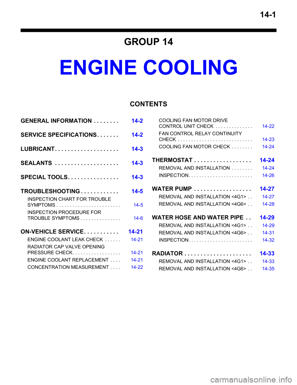
14-1
GROUP 14
ENGINE COOLING
CONTENTS
GENERAL INFORMATION . . . . . . . .14-2
SERVICE SPECIFICATIONS . . . . . . .14-2
LUBRICANT . . . . . . . . . . . . . . . . . . . .14-3
SEALANTS . . . . . . . . . . . . . . . . . . . .14-3
SPECIAL TOOLS . . . . . . . . . . . . . . . .14-3
TROUBLESHOOTING . . . . . . . . . . . .14-5
INSPECTION CHART FOR TROUBLE
SYMPTOMS . . . . . . . . . . . . . . . . . . . . . . . . 14-5
INSPECTION PROCEDURE FOR
TROUBLE SYMPTOMS . . . . . . . . . . . . . . . 14-6
ON-VEHICLE SERVICE . . . . . . . . . . .14-21
ENGINE COOLANT LEAK CHECK . . . . . . 14-21
RADIATOR CAP VALVE OPENING
PRESSURE CHECK . . . . . . . . . . . . . . . . . . 14-21
ENGINE COOLANT REPLACEMENT . . . . 14-21
CONCENTRATION MEASUREMENT . . . . 14-22
COOLING FAN MOTOR DRIVE
CONTROL UNIT CHECK . . . . . . . . . . . . . . 14-22
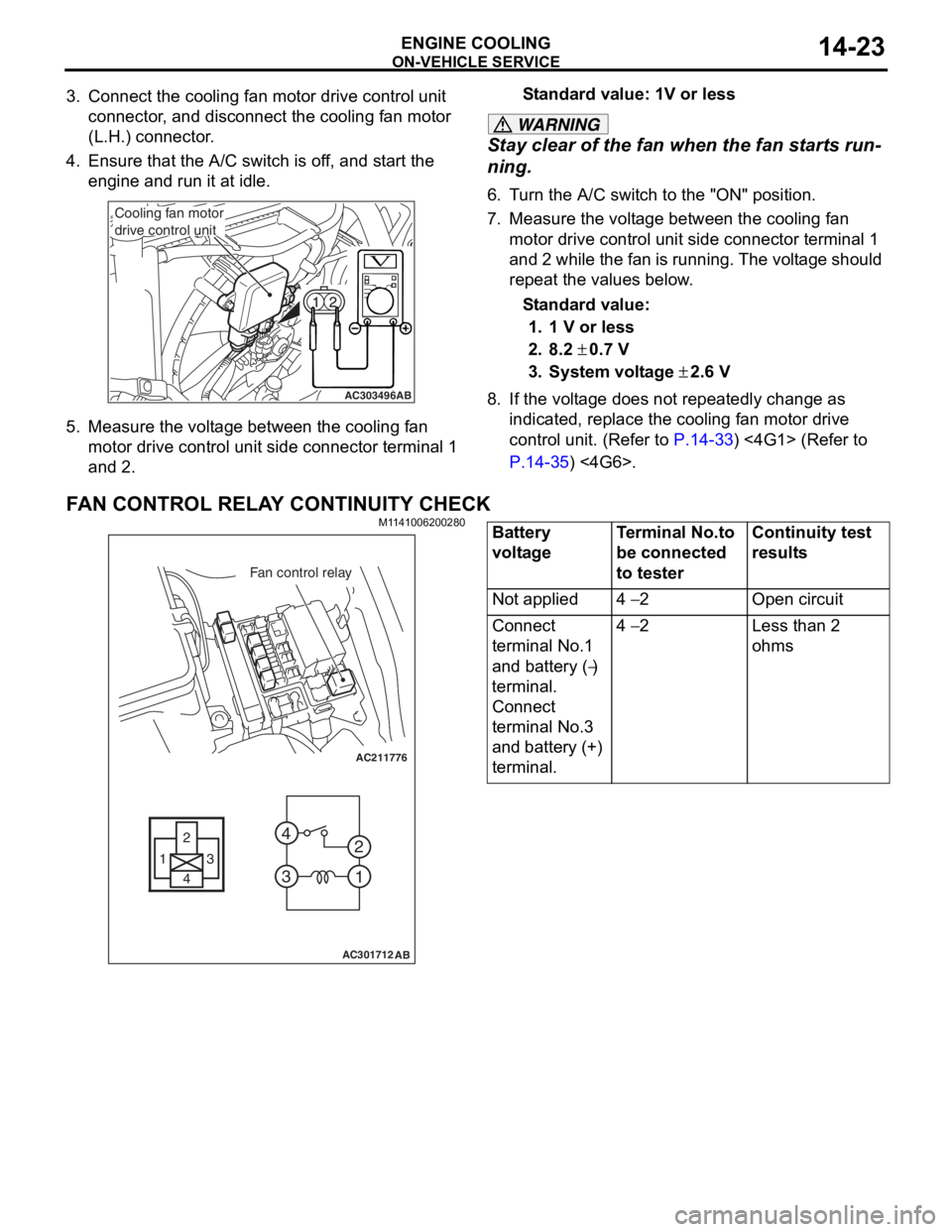
FAN CONTROL RELAY CONTINUITY
CHECK . . . . . . . . . . . . . . . . . . . . . . . . . . . . 14-23
COOLING FAN MOTOR CHECK . . . . . . . . 14-24
THERMOSTAT . . . . . . . . . . . . . . . . . .14-24
REMOVAL AND INSTALLATION . . . . . . . . 14-24
INSPECTION. . . . . . . . . . . . . . . . . . . . . . . . 14-26
WATER PUMP . . . . . . . . . . . . . . . . . .14-27
REMOVAL AND INSTALLATION <4G1> . . 14-27
REMOVAL AND INSTALLATION <4G6> . . 14-28
WATER HOSE AND WATER PIPE . .14-29
REMOVAL AND INSTALLATION <4G1> . . 14-29
REMOVAL AND INSTALLATION <4G6> . . 14-31
INSPECTION. . . . . . . . . . . . . . . . . . . . . . . . 14-32
RADIATOR . . . . . . . . . . . . . . . . . . . . .14-33
REMOVAL AND INSTALLATION <4G1> . . 14-33
REMOVAL AND INSTALLATION <4G6> . . 14-35
Page 20 of 800

TROUBLESHOOTING
ENGINE COOLING14-6
INSPECTION PROCEDURE FOR
TROUBLE SYMPTOMS
INSPECTION PROCEDURE 1: Cooling Fan (L.H.) and Cooling Fan (R.H.) <4G1 (Vehicles with A/C)> or
A/C Condenser Fan <4G6> do not Operate
Wire colour code
B : Black LG : Light green
G : Green L : Blue
W : White Y : Yellow
SB : Sky blue BR : Brown
O : Orange GR : Gray
R : Red P : Pink V : Violet
FAN CONTROL
RELAY
A-09XENGINE CONTROL
RELAY
B-16X
AC303577
A-18-1
COOLING FAN
MOTOR (L.H.)
COOLING FAN
MOTOR (R.H.)
<4G1 (VEHICLES
WITH A/C>
OR
A/C CONDENSER
FAN MOTOR <4G6> A-18-2
A-18
COOLING FAN
MOTOR DRIVE
CONTROL UNIT 1 A-13
12 C-111
ENGINE-ECU
ENGINE-A/T-ECU
21 C-123
18 C-122
615 121179
810234
(MU802322)
(MU801824)
C-123
(MU803784)C-122
(MU802611)A-13
C-111 L
L 2
22 11
1B
L
2
3
4
B-W
FUSIBLE
LINK No.2
B3
1
R-Y
R-Y
8 A-13
11 C-111
615 121179
810234
(MU802611)
J/C (6)
C-12
C-134
R-Y
3328
A-13
C-111
Cooling Fan (L.H.) and Cooling Fan (R.H.) or A/C Condenser Fan Drive Circut
AB
CIRCUIT OPERA T ION
•The cooling fan motor drive contro l unit is pow-
ered from fusible link (2).
•The engine-ECU
water t
e mpe r ature sensor unit and the vehicle
speed sensor
senso
r to control the speed of the coo ling
fan
moto r (L.H.) and the cooling fa n mot o r (R.H.)
<4G1 (V
ehicles wit h A/C)> or A/C co ndenser fan
motor <4G6>.
Page 21 of 800
TROUBLESHOOTING
ENGINE COOLING14-7
•The engine-ECU
controls the cooling fan motor drive control
unit to activate the cooling fan motor (L.H.) and
the cooling fan motor (R.H.) <4G1 (Vehicles with
A/C)> or A/C condenser fan motor <4G6>.
TECHNICAL DESCRIPTION
•The cause could be a malfunction of the cooling
fan motor drive control unit power supply or earth
circuit.
•If the communication line wiring harness between
the cooling fan motor drive control unit and the
engine-ECU
short-circuited to earth, the cooling fan motor
(L.H.) and the cooling fan motor (R.H.) <4G1
(Vehicles with A/C)> or the A/C condenser fan
motor <4G6> will not rotate.
•The cause could also be a malfunction of the
cooling fan motor (L.H.).
•The cause could also be a malfunction of imput
signal from the A/C switch, the water temperature
sensor unit and the vehicle speed sensor
or the output shaft speed sensor to the
engine-ECU
•The cause could also be a malfunction of the
cooling fan motor drive control unit or the
engine-ECU
TROUBLESHOOTING HINTS
•Malfunction of fusible link (2)
•Malfunction of fan control relay
•Malfunction of cooling fan motor (L.H.)
•Malfunction of cooling fan motor drive control unit
•Malfunction of engine-ECU
engine-A/T-ECU
•Damaged wiring harness or connector
DIAGNOSIS
STEP 1. Check the cooling fan motor (L.H.).
Refer to P.14-24.
Q: Is the cooling fan motor (L.H.) in good condition?
YES : Go to Step 2 .
NO : Replace the cooling fan motor (L.H.) (Refer
to
P.14-33) <4G1> (Refer to P.14-35)
<4G6>. Then go to Step 24 .
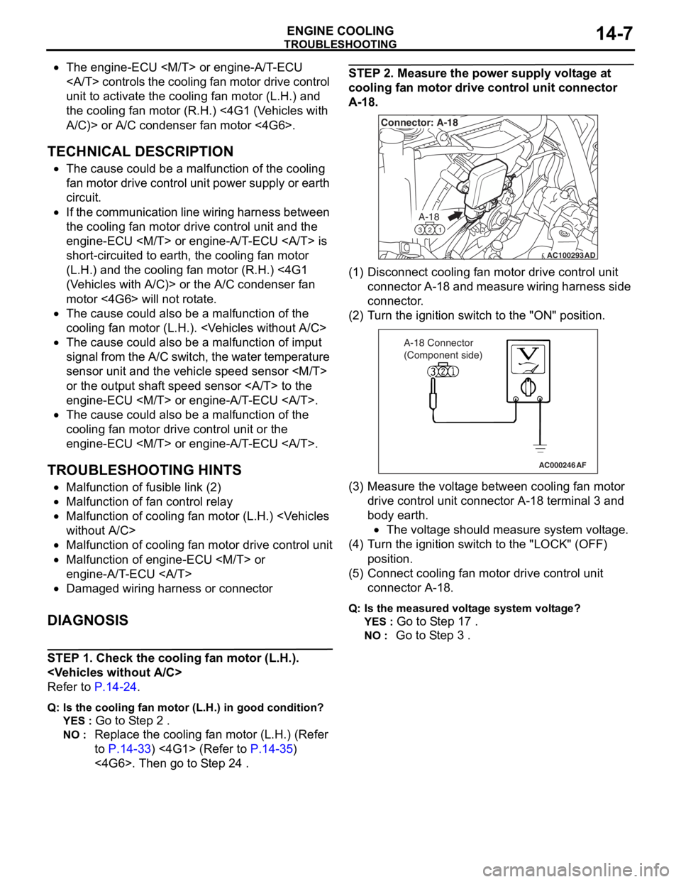
STEP 2. Measure the power supply voltage at
cooling fan motor drive control unit connector
A-18.
AC100293
A-18
321
Connector: A-18
AD
(1)D isconn ect cooling f an motor drive contro l unit
conne ctor A-18 a nd measure wirin g har ness side
connector .
(2)T urn t he ig nition switch t o the "ON" positio n.
AC000246AF
A-18 Connector
(Component side)
(3)M easu r e the volt age between cooling fan motor
drive control unit con nect o r A-18 te rmin al 3 a nd
bod y ea rth.
•The voltage shou ld measu r e syste m volt age.
(4)T urn t he ig nition switch t o the "L OCK" (OF F )
position.
(5)C onne ct cooling fa n mot o r drive control unit
connector A-18.
Q:Is t h e mea s ure d volt a g e sy ste m v o lt ag e?
YES : Go to S t ep 1 7 .
NO : Go to S t ep 3 .
Page 22 of 800
TROUBLESHOOTING
ENGINE COOLING14-8
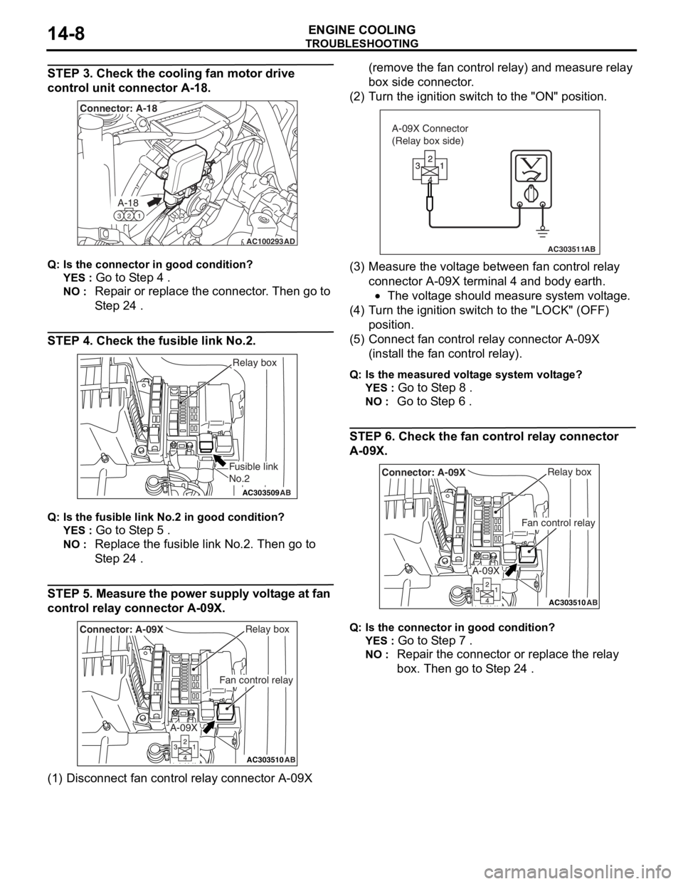
STEP 3. Check the cooling fan motor drive
control unit connector A-18.
AC100293
A-18
321
Connector: A-18
AD
Q:Is t h e con n ec tor in goo d c ondit i o n ?
YES : Go to S t ep 4 .
NO : Repa ir or replace the conne ctor . Th en go to
S
t ep 24
.
STEP 4 . Ch eck the fusible link No.2.
AC303509AB
Fusible link
No.2
Relay box
Q:Is t h e fu sible link No.2 in good c ondition ?
YES : Go to S t ep 5 .
NO : Replac e th e fusible lin k No.2. Then g o to
S
t ep 24
.
STEP 5. Measure the po wer suppl y volt age at fan
control relay
connect or A-09 X.
AC303510AB
Fan control relay
Relay boxConnector: A-09X
A-09X
(1)D isconn ect f an co ntrol relay co nnector A-09X (remove the fan control relay) and measure re lay
box side connector .
(2)
T urn t he ig nition switch t o the "ON" positio n.
AC303511AB
A-09X Connector
(Relay box side)
(3)M easu r e the volt age between fan control rela y
connector A-09X te rmin al 4 and bo dy e a rth.
•The voltage shou ld measu r e syste m volt age.
(4)T urn t he ig nition switch t o the "L OCK" (OF F )
position.
(5) C onne ct fa n con t rol re lay con necto r A-09X
(inst a ll the fan control relay).
Q:Is t h e mea s ure d volt a g e sy ste m v o lt ag e?
YES : Go to S t ep 8 .
NO : Go to S t ep 6 .
STEP 6 . Check the fan con trol re lay co nnector
A-0
9 X.
AC303510AB
Fan control relay
Relay boxConnector: A-09X
A-09X
Q:Is t h e con n ec tor in goo d c ond it io n?
YES : Go to S t ep 7 .
NO : Repa ir th e con nect o r or rep l ace the re lay
box. Then
go to S t ep 24
.
Page 23 of 800
TROUBLESHOOTING
ENGINE COOLING14-9
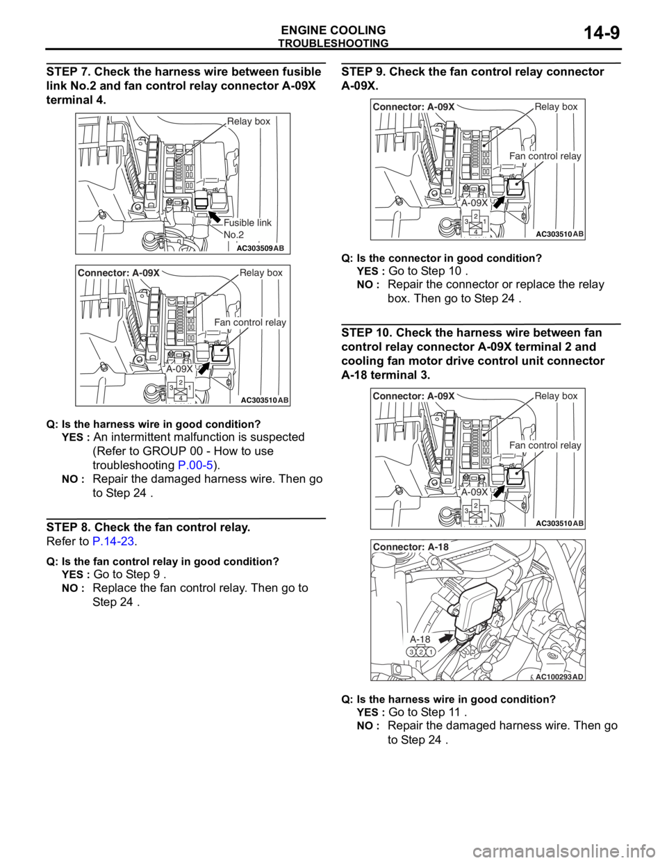
STEP 7. Check the harness wire between fusible
link No.2 and fan control relay connector A-09X
terminal 4.
AC303509AB
Fusible link
No.2
Relay box
AC303510AB
Fan control relay
Relay boxConnector: A-09X
A-09X
Q:Is t h e har n es s wire in good c ondition ?
YES : An intermittent malf unction is suspe c ted
(Refer to GROUP 00 - How to use
troub lesh ooting
P.00-5).
NO : Repa ir the dama ged harness wire. Then go
to S
t ep 2 4
.
STEP 8. Ch eck the fan con trol re lay .
Refe r to P.14-23.
Q:Is t h e fa n cont rol relay in go od con d it ion?
YES : Go to S t ep 9 .
NO : Replac e th e fan contro l relay . Then go to
S
t ep 24
.
ST EP 9 . Check the fan con trol re lay co nnector
A-0
9 X.
AC303510AB
Fan control relay
Relay boxConnector: A-09X
A-09X
Q:Is t h e con n ec tor in goo d c ond it io n?
YES : Go to S t ep 1 0 .
NO : Repa ir th e con nect o r or rep l ace the re lay
box. Then
go to S t ep 24
.
STEP 1 0 . Check t he harness wire b e twe en fan
control relay
connec tor A-0 9 X terminal 2 and
cooling f
an motor drive control uni t connec tor
A-1
8 terminal 3.
AC303510AB
Fan control relay
Relay boxConnector: A-09X
A-09X
AC100293
A-18
321
Connector: A-18
AD
Q:Is t h e har n es s wire in good c ondit i on ?
YES : Go to S t ep 1 1 .
NO : Repa ir the dama ged harness wire. Then go
to S
t ep 2 4
.
Page 24 of 800
TROUBLESHOOTING
ENGINE COOLING14-10
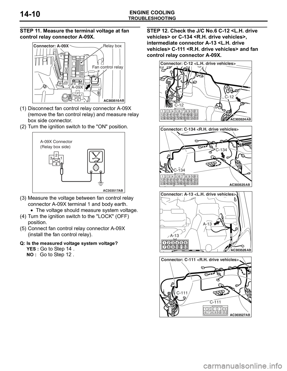
STEP 11. Measure the terminal voltage at fan
control relay connector A-09X.
AC303510AB
Fan control relay
Relay boxConnector: A-09X
A-09X
(1)D isconn ect f an co ntrol relay co nnector A-09X
(remove the fan control relay) and measure re lay
box side connector .
(2)T urn t he ig nition switch to the "ON" positio n.
AC303517AB
A-09X Connector
(Relay box side)
(3)M easu r e the volt age between fan control rela y
co nnector A-09X te rmin al 1 and bo dy ea rth.
•The voltage should measu r e syste m volt age.
(4)T urn t he ig nition switch to the "L OCK" (OFF )
position.
(5) C onne ct fa n con t rol re lay conn ecto r A-09X
(inst a ll the fan control relay).
Q:Is t h e mea s ure d volt ag e sy ste m v o lt ag e?
YES : Go to S t ep 14 .
NO : Go to S t ep 12 .
STEP 1 2 . Check t he J/C No.6 C-12
s > or C-134
intermedia
t e conne ctor A-13
s > C-1 1 1
control relay
connec tor A-0 9 X.
AC303524
Connector: C-12
AB
C-12
C-12
AC303525
Connector: C-134
AB
C-134
C-134
AC303526
Connector: A-13
AB
A-13
A-13
AC303527
Connector: C-111
AB
C-111
C-111
615121179
810234
Page 25 of 800
AC303510AB
Fan control relay
Relay boxConnector: A-09X
A-09X
TROUBLESHOOTING
ENGINE COOLING14-11
Q: Are t h er e conn ect ors in go od cond it ion?
YES : Go to S t ep 13 .
NO : Repa ir or replace the conne ctor . Th en go to
S
t ep 24
.
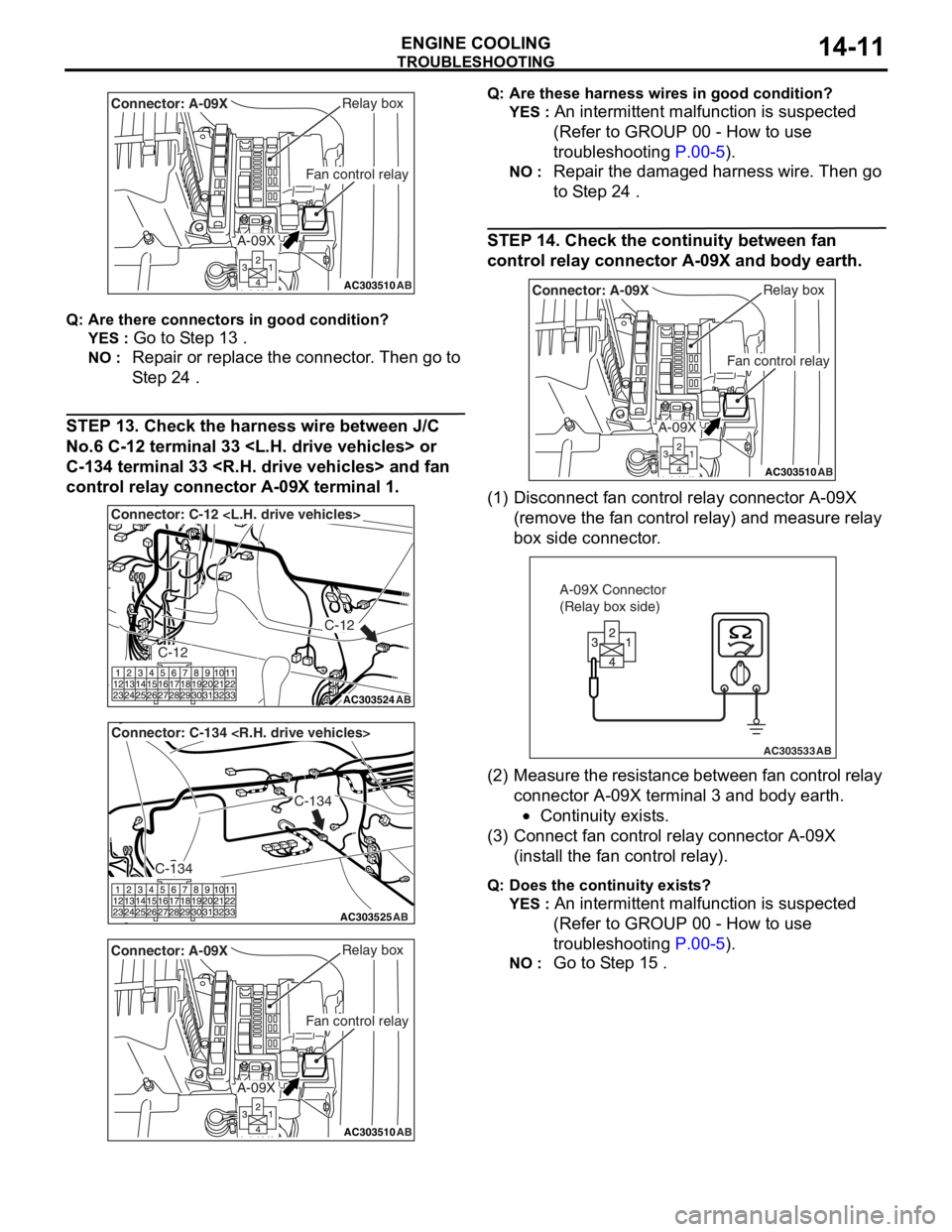
STEP 1 3 . Check th e harness wire b e twee n J/C
No.
6 C-12 termina l 33
C-1
34 termina l 33
control relay
connect or A-09 X terminal 1 .
AC303524
Connector: C-12
AB
C-12
C-12
AC303525
Connector: C-134
AB
C-134
C-134
AC303510AB
Fan control relay
Relay boxConnector: A-09X
A-09X
Q:Are t h es e har n es s wires in go od cond it ion?
YES : An intermittent malf unction is suspe c ted
(Refer to GROUP 00 - How to use
troub leshooting
P.00-5).
NO : Repa ir the dama ged harness wire. Then go
to S
t ep 2 4
.
STEP 1 4 . Check t he contin uity between fan
control relay
connec tor A-0 9 X and bod y earth.
AC303510AB
Fan control relay
Relay boxConnector: A-09X
A-09X
(1)D isconn ect f an control relay co nnector A-09X
(remove the fan control relay) and measure re lay
box side connector .
AC303533AB
A-09X Connector
(Relay box side)
(2) M ea sure th e resi st anc e b e t w e e n f an con t rol re lay
connector A-09X te rmin al 3 and bo dy e a rth.
•Continu i ty exist s .
(3)C onne ct fa n con t rol re lay con necto r A-09X
(inst a ll the fan control relay).
Q:Doe s the cont inuity e x ist s ?
YES : An intermittent malf unction is suspe c ted
(Refer to GROUP 00 - How to use
troub leshooting
P.00-5).
NO : Go to S t ep 15 .
Page 26 of 800
TROUBLESHOOTING
ENGINE COOLING14-12
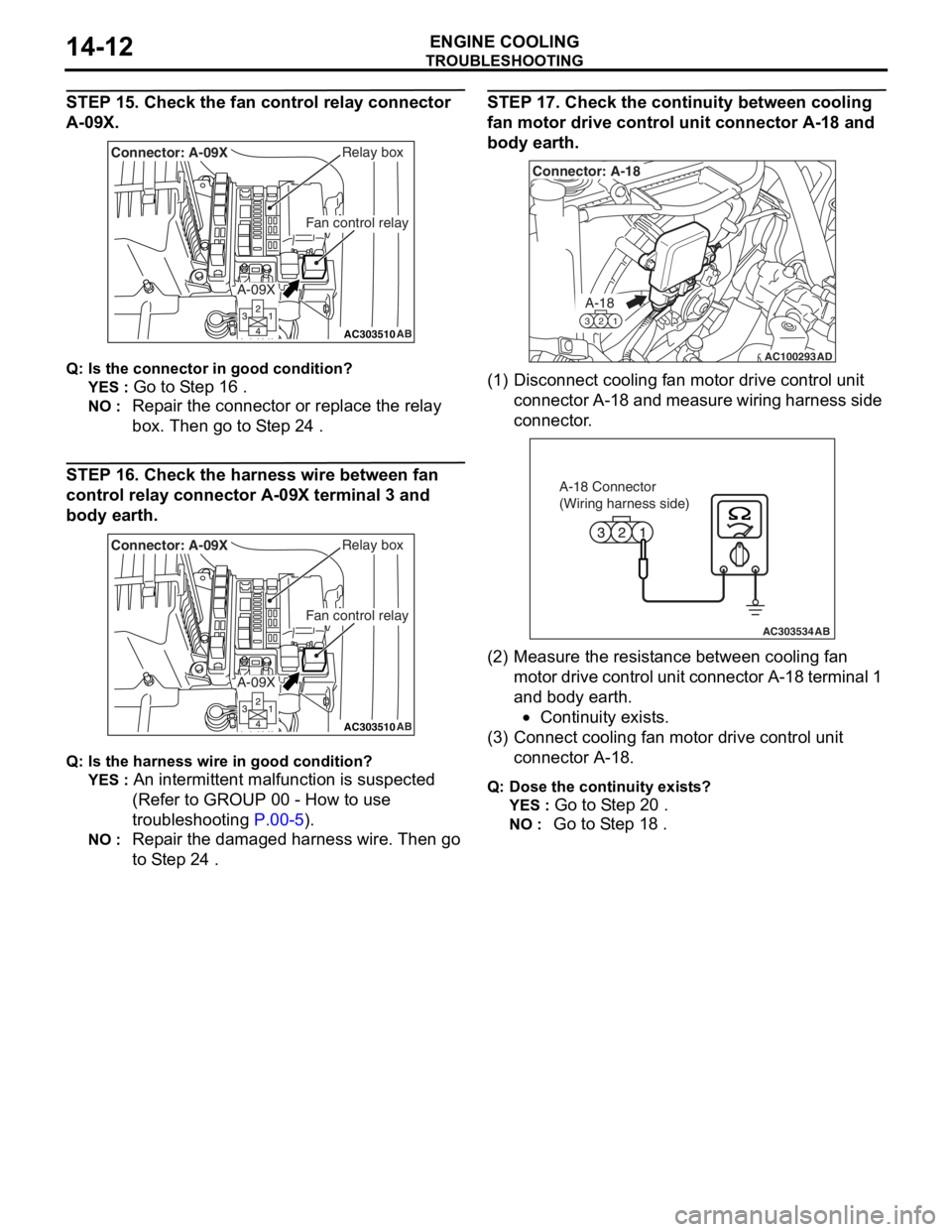
STEP 15. Check the fan control relay connector
A-09X.
AC303510AB
Fan control relay
Relay boxConnector: A-09X
A-09X
Q:Is t h e con n ec tor in goo d c ondit i o n ?
YES : Go to S t ep 16 .
NO : Repa ir the con nect o r or rep l ace the re lay
box. Then
go to S t ep 24
.
STEP 16 . Check th e harness wire b e twee n fan
control relay
connect or A-09 X terminal 3 and
body ea
rth.
AC303510AB
Fan control relay
Relay boxConnector: A-09X
A-09X
Q:Is t h e har n es s wire in good c ondition ?
YES : An intermittent malf unction is suspe c ted
(Refer to GROUP 00 - How to use
troub lesh ooting
P.00-5).
NO : Repa ir the dama ged harness wire. Then go
to S
t ep 2 4
.
STEP 1 7 . Check t he contin uity between cooling
fan motor drive
control un it connec tor A-1 8 and
body ea
rth.
AC100293
A-18
321
Connector: A-18
AD
(1)D isconn ect cooling f an motor drive contro l unit
conne ctor A-18 a nd measure wirin g har ness side
connector .
AC303534AB
A-18 Connector
(Wiring harness side)
(2)M easu r e the re sist ance between cooling fan
mot o r d r ive cont rol unit conn ecto r A-1 8 te rmina l 1
and body earth .
•Continu i ty exist s .
(3)C onne ct cooling fa n mot o r drive control unit
connector A-18.
Q:Dos e the cont inuity e x ist s ?
YES : Go to S t ep 2 0 .
NO : Go to S t ep 18 .
Page 30 of 800
TROUBLESHOOTING
ENGINE COOLING14-16
INSPECTION PROCEDURE 2: Cooling Fan (L.H.) and Cooling Fan (R.H.) <4G1 (Vehicles with A/C)> or
A/C Condenser Fan <4G6> do not Change Speed or Stop
COOLING FAN (L.H.) AND COOLING FAN
(R.H.) OR A/C CONDENSER FAN DRIVE
CIRCUIT
Refer to P.14-6.
CIRCUIT OPERATION
Refer to P.14-6.
TECHNICAL DESCRIPTION
•If the communication line wiring harness between
the cooling fan motor drive control unit and the
engine-ECU
is open, the cooling fan motor (L.H.) and
the cooling fan motor (R.H.) <4G1 (Vehicles with
A/C)>, or the A/C condenser fan motor <4G6>
rotate to prevent the engine from overheating.
•If the system voltage is continuously supplied to
the cooling fan motor drive control unit by a fan
motor relay malfunction and a short circuit on the
cooling fan motor drive control unit power supply
wiring harness, the cooling fan motor (L.H.) and
the cooling fan motor (R.H.) <4G1 (Vehicles with
A/C)>, or the A/C condenser fan motor <4G6>
rotate.
•The cause could also be a malfunction of the
cooling fan motor (L.H.).
•The cause could also be a malfunction of input
signal from the A/C switch, the water temperature
sensor unit and the vehicle speed sensor
or the output shaft speed sensor to the
engine-ECU
•The cause could also be a malfunction of the
cooling fan motor drive control unit or the
engine-ECU
TROUBLESHOOTING HINTS
•Malfunction of fan control relay
•Malfunction of cooling fan motor (L.H.)
•Malfunction of cooling fan motor drive control unit
•Malfunction of engine-ECU
engine-A/T-ECU
•Damaged wiring harness or connector
DIAGNOSIS
STEP 1. Check the fan control relay.
Refer to P.14-23.
Q: Is the fan control relay in good condition?
YES : Go to Step 2 .
NO : Replace the fan control relay. Then go to
Step 8
.
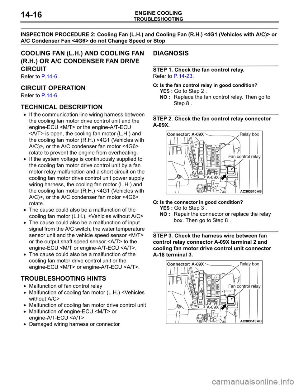
STEP 2. Check the fan control relay connector
A-09X.
AC303510AB
Fan control relay
Relay boxConnector: A-09X
A-09X
Q:Is t h e con n ec tor in goo d c ond it io n?
YES : Go to S t ep 3 .
NO : Repa ir th e con nect o r or rep l ace the re lay
box. Then
go to S t ep 8
.
STEP 3 . Check the harness wire be twee n fan
control relay
connec tor A-0 9 X terminal 2 and
cooling f
an motor drive control uni t connec tor
A-1
8 terminal 3.
AC303510AB
Fan control relay
Relay boxConnector: A-09X
A-09X
Page 37 of 800
ON-VEHICLE SERVICE
ENGINE COOLING14-23
3. Connect the cooling fan motor drive control unit connector, and disconnect the cooling fan motor
(L.H.) connector.
4. Ensure that the A/C switch is off, and start the engine and run it at idle.
AC303496AB
Cooling fan motor
drive control unit
5.Measure the volt ag e betwee n the cooling f an
motor d r ive cont rol un it side conne ctor t e rminal 1
an d 2.
St andard va lue: 1V or le ss
WARNING
Stay clear of the fan when the fan starts run-
ning.
6. Turn the A/C switch to the "ON" position.
7. Measure the voltage between the cooling fan
motor drive control unit side connector terminal 1
and 2 while the fan is running. The voltage should
repeat the values below.
Standard value:
1. 1 V or less
2. 8.2 ± 0.7 V
3. System voltage ± 2.6 V
8. If the voltage does not repeatedly change as indicated, replace the cooling fan motor drive
control unit. (Refer to
P.14-33) <4G1> (Refer to
P.14-35) <4G6>.
FAN CONTROL RELAY CONTINUITY CHECK
M1141006200280
AC211776
13
4 2
3 4
1
2
AC301712
Fan control relay
AB
Battery
voltageTerminal No.to
be connected
to testerContinuity test
results
Not applied4 − 2Open circuit
Connect
terminal No.1
and battery (
−)
terminal.
Connect
terminal No.3
and battery (+)
terminal.
4 − 2Less than 2
ohms