torque MITSUBISHI LANCER IX 2006 Service Manual
[x] Cancel search | Manufacturer: MITSUBISHI, Model Year: 2006, Model line: LANCER IX, Model: MITSUBISHI LANCER IX 2006Pages: 800, PDF Size: 45.03 MB
Page 10 of 800
ON-VEHICLE SERVICE
ENGINE LUBRICATION12-4
ON-VEHICLE SERVICE
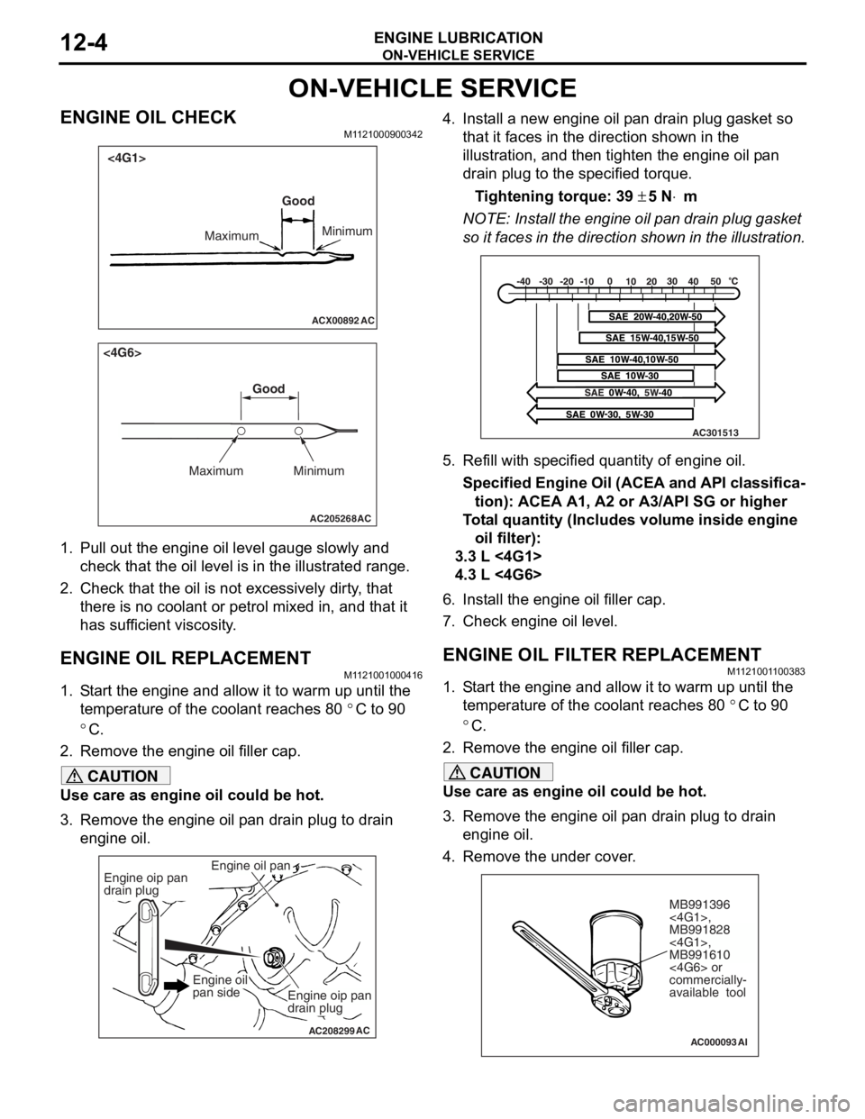
ENGINE OIL CHECKM1121000900342
ACX00892 AC
Good
Maximum Minimum
<4G1>
AC205268
Maximum MinimumGood
AC
<4G6>
1.
Pull ou t the en gine oil level ga uge slowly and
check tha t the o il level is in t he illustrated range.
2.Check t hat the oil is not excessively dirty , that
th ere is no coolant or p e trol mixed in, and that it
ha s s u f f i c ie nt vi sc osi t y .
ENGINE OIL REPLACEMENT
M1121 0010 0041 6
1.S t art the engin e and allow it to war m up until the
te mpera t ure of the coola n t reaches 80
°C to 90
°C.
2.Remove the en gine oil filler ca p.
CAUTION
Use care as engine oil could be hot.
3. Remove the engine oil pan drain plug to drain
engine oil.
AC208299
Engine oil pan
AC
Engine oip pan
drain plug
Engine oip pan
drain plug
Engine oil
pan side
4. Install a new engine oil pan drain plug gasket so
that it faces in the direction shown in the
illustration, and then tighten the engine oil pan
drain plug to the specified torque.
Tightening torque: 39 ± 5 N⋅m
NOTE: Install the engine oil pan drain plug gasket
so it faces in the direction shown in the illustration.
AC301513
5. Refill with specifi ed quantity of engine oil.
Specified Engine Oil (ACEA and API classifica-
tion): ACEA A1, A2 or A3/API SG or higher
Total quantity (Includes volume inside engine
oil filter):
3.3 L <4G1>
4.3 L <4G6>
6. Install the engine oil filler cap.
7. Check engine oil level.
ENGINE OIL FILTER REPLACEMENTM1121001100383
1. Start the engine and allow it to warm up until the temperature of the coolant reaches 80
°C to 90
°C.
2. Remove the engine oil filler cap.
CAUTION
Use care as engine oil could be hot.
3. Remove the engine oil pan drain plug to drain engine oil.
4. Remove the under cover.
AC000093
MB991396
<4G1>,
MB991828
<4G1>,
MB991610
<4G6> or
commercially-
available tool
AI
Page 11 of 800
ON-VEHICLE SERVICE
ENGINE LUBRICATION12-5
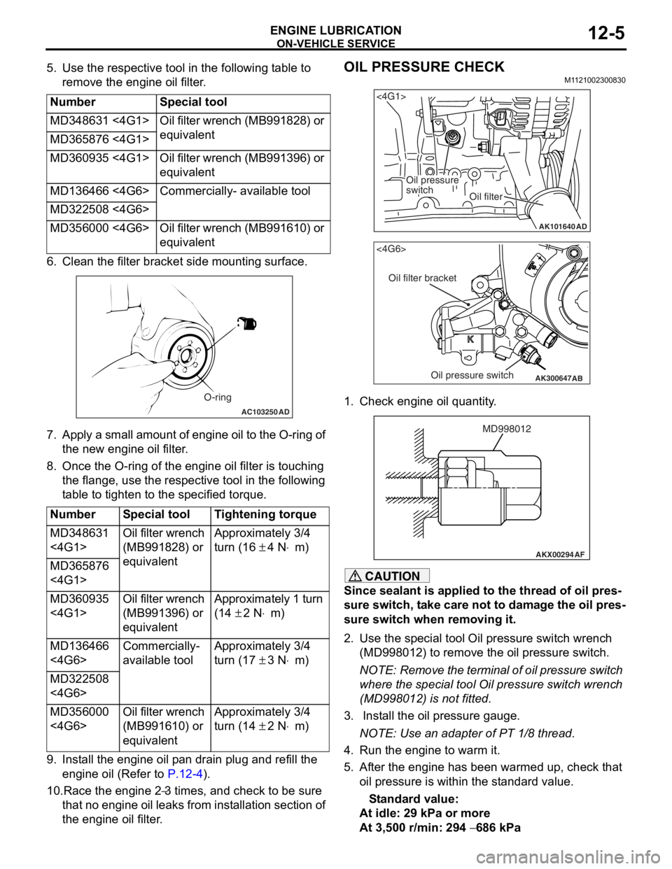
5. Use the respective tool in the following table to remove the engine oil filter.
NumberSpecial tool
MD348631 <4G1>Oil filter wrench (MB991828) or
equivalent
MD365876 <4G1>
MD360935 <4G1>Oil filter wrench (MB991396) or
equivalent
MD136466 <4G6>Commercially- available tool
MD322508 <4G6>
MD356000 <4G6>Oil filter wrench (MB991610) or
equivalent
6. Cle an the filt er bracket side mou n ting surfa c e.
AC103250AD
O-ring
7.Ap ply a small a m ou nt o f en gine o i l to th e O-rin g of
th e new eng ine oil f ilte r .
8.Once the O-ring of the engine oil filter is tou c hing
th e flange, use the resp ective tool in the following
t able to tighten to the specified tor que.
NumberSpecial toolTightening torque
MD348631
<4G1>Oil filter wrench
(MB991828) or
equivalentApproximately 3/4
turn (16
± 4 N⋅m)
MD365876
<4G1>
MD360935
<4G1>Oil filter wrench
(MB991396) or
equivalentApproximately 1 turn
(14
± 2 N⋅m)
MD136466
<4G6>Commercially-
available toolApproximately 3/4
turn (17
± 3 N⋅m)
MD322508
<4G6>
MD356000
<4G6>Oil filter wrench
(MB991610) or
equivalentApproximately 3/4
turn (14
± 2 N⋅m)
9.In st all the en gine oil p a n drain plu g and refill the
en gine oil (Re f er to
P.12-4).
10.Race the en gine 2−3 times, and che ck to be sure
th
at n
o
en
gin
e
oil leaks fr om in st allation sectio n of
th
e engine oil filter
.
OIL PRESSURE CHECK
M1 121 0023 0083 0
AK101640
<4G1>
Oil pressure
switch
Oil filter
AD
AK300647
AB
<4G6>
Oil filter bracket
Oil pressure switch
1.Check e ngin e oil quan tity .
AKX00294
MD998012
AF
CAUTION
Since sealant is applied to the thread of oil pres-
sure switch, take care not to damage the oil pres-
sure switch when removing it.
2. Use the special tool Oil pressure switch wrench
(MD998012) to remove the oil pressure switch.
NOTE: Remove the terminal of oil pressure switch
where the special tool Oil pressure switch wrench
(MD998012) is not fitted.
3. Install the oil pressure gauge.
NOTE: Use an adapter of PT 1/8 thread.
4. Run the engine to warm it.
5. After the engine has been warmed up, check that oil pressure is within the standard value.
Standard value:
At idle: 29 kPa or more
At 3,500 r/min: 294 − 686 kPa
Page 12 of 800
ON-VEHICLE SERVICE
ENGINE LUBRICATION12-6
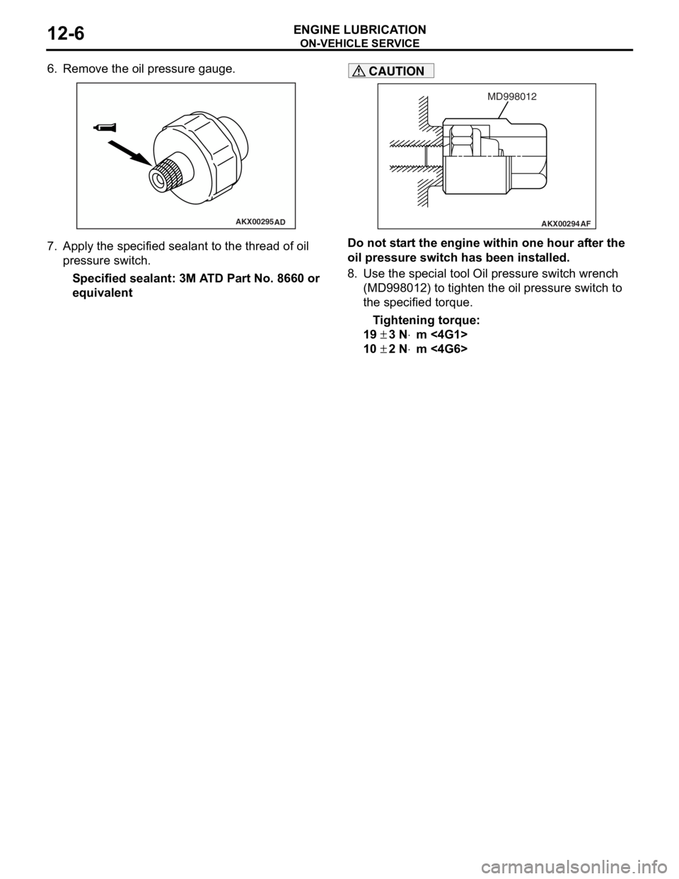
6. Remove the oil pressure gauge.
AKX00295AD
7.App l y t he sp ecified sealant to the thr ead of oil
pres sure sw itc h .
Specified sealan t: 3M A T D Part No. 8660 or
equival
ent
AKX00294
MD998012
AF
CAUTION
Do not start the engine within one hour after the
oil pressure switch has been installed.
8. Use the special tool Oil pressure switch wrench (MD998012) to tighten the oil pressure switch to
the specified torque.
Tightening torque:
19 ± 3 N⋅m <4G1>
10 ± 2 N⋅m <4G6>
Page 36 of 800
AC200625
Cylinder block
drain plug
AC
ON-VEHICLE SER VICE
ENGINE COOLING14-22
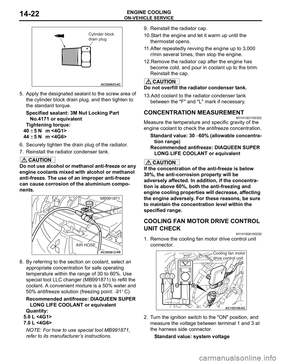
5.App l y the designa ted sealant to t he scre w area of
th e cylin der block drain plu g , and then tighten to
th e st and ard torq ue.
Sp e c ified s ealant: 3 M Nut Loc king Part
No. 4171 o r e quivale n t
Ti ghtenin g torque:
40 ± 5 N⋅m <4G1>
44 ± 5 N⋅m <4G6>
6.Securely tighten t he drain plug of t he radiator .
7.Reinst all the ra diato r con denser t ank.
CAUTION
Do not use alcohol or methanol anti-freeze or any
engine coolants mixed with alcohol or methanol
anti-freeze. The use of an improper anti-freeze
can cause corrosion of the aluminium compo
-
nents.
AC303612AB
MB991871
AIR HOSE
8. By referring to the section on coolant, select an
appropriate concentration for safe operating
temperature within the range of 30 to 60%. Use
special tool LLC changer (MB991871) to refill the
coolant. A convenient mixture is a 50% water and
50% antifreeze solution (freezing point:
−31°C).
Recommended antifreeze: DIAQUEEN SUPER LONG LIFE COOLANT or equivalent
Quantity:
5.0 L <4G1>
7.0 L <4G6>
NOTE: For how to use special tool MB991871,
refer to its manufacturer’s instructions.
9. Reinstall the radiator cap.
10.Start the engine and let it warm up until the thermostat opens.
11.After repeatedly revving the engine up to 3,000 r/min several times, then stop the engine.
12.Remove the radiator cap after the engine has become cold, and pour in coolant up to the brim.
Reinstall the cap.
CAUTION
Do not overfill the radiator condenser tank.
13.Add coolant to the radiator condenser tank between the "F" and "L" mark if necessary.
CONCENTRATION MEASUREMENT
M1141001100352
Measure the temperature and specific gravity of the
engine coolant to check the antifreeze concentration.
Standard value: 30 − 60% (allowable concentra-
tion range)
Recommended antifreeze: DIAQUEEN SUPER
LONG LIFE COOLANT or equivalent
CAUTION
If the concentration of the anti-freeze is below
30%, the anti-corrosion property will be
adversely affected. In addition, if the concentra
-
tion is above 60%, both the anti-freezing and
engine cooling properties will decrease, affecting
the engine adversely. For these reasons, be sure
to maintain the concentration level within the
specified range.
COOLING FAN MOTOR DRIVE CONTROL
UNIT CHECK
M1141006100250
1. Remove the cooling fan motor drive control unit connector.
AC103195
Y1716AU
1
23
AC
Cooling fan motor
drive control unit
2. Turn the ignition switch to the "ON" position, and
measure the voltage between terminal 1 and 3 at
the harness side connector.
Standard value: system voltage
Page 92 of 800
IGNITION SYSTEM
ENGINE ELECTRICAL16-30
IGNITION SYSTEM
GENERAL INFORMATIONM1163000100294
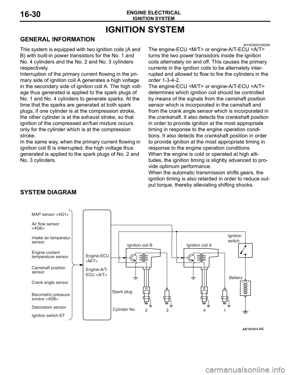
This system is equipped with two ignition coils (A and
B) with built-in power transistors for the No. 1 and
No. 4 cylinders and the No. 2 and No. 3 cylinders
respectively.
Interruption of the primary current flowing in the pri-
mary side of ignition coil A generates a high voltage
in the secondary side of ignition coil A. The high volt
-
age thus generated is applied to the spark plugs of
No. 1 and No. 4 cylinders to generate sparks. At the
time that the sparks are generated at both spark
plugs, if one cylinder is at the compression stroke,
the other cylinder is at the exhaust stroke, so that
ignition of the compressed air/fuel mixture occurs
only for the cylinder which is at the compression
stroke.
In the same way, when the primary current flowing in
ignition coil B is interrupted, the high voltage thus
generated is applied to the spark plugs of No. 2 and
No. 3 cylinders.
The engine-ECU
turns the two power transistors inside the ignition
coils alternately on and off. This causes the primary
currents in the ignition coils to be alternately inter
-
rupted and allowed to flow to fire the cylinders in the
order 1-3-4-2.
The engine-ECU
determines which ignition coil should be controlled
by means of the signals from the camshaft position
sensor which is incorporated in the camshaft and
from the crank angle sensor which is incorporated in
the crankshaft. It also detects the crankshaft position
in order to provide ignition at the most appropriate
timing in response to the engine operation condi
-
tions. It also detects the crankshaft position in order
to provide ignition at the most appropriate timing in
response to the engine operation conditions.
When the engine is cold or operated at high alti-
tudes, the ignition timing is slightly advanced to pro-
vide optimum performance.
When the automatic transmission shifts gears, the
ignition timing is also retarded in order to reduce out
-
put torque, thereby alleviating shifting shocks.
SYSTEM DIAGRAM
AK101074
Air flow sensor
<4G6> MAP sensor <4G1>
Intake air temperatur
sensor
Engine coolant
temperature sensor
Camshaft position
sensor
Crank angle sensor
Barometric pressure
sonsor <4G6>
Detonatoin sensor
Ignition switch-ST Engine-A/T-
ECU Engine-ECU
Ignition coil B
Cylinder No. 23 4
AG
1
Spark plug Ignition coil A
Ignition
switch
Battery
Page 106 of 800
IGNITION SYSTEM
ENGINE ELECTRICAL16-44
REMOVAL SERVICE POINT
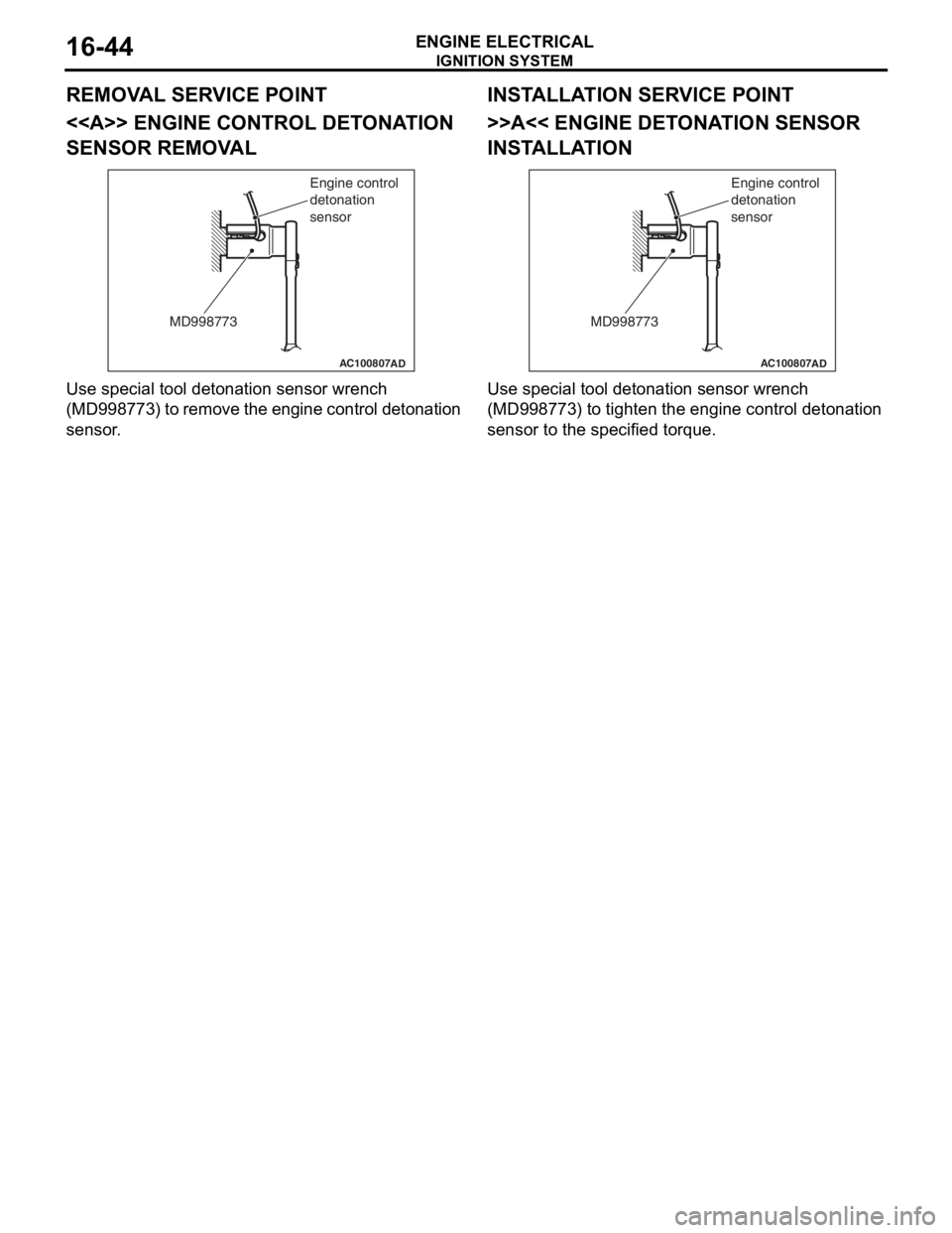
<> ENGINE CONTROL DETONATION
SENSOR REMOVAL
AC100807
MD998773Engine control
detonation
sensor
AD
Use sp
ecial to ol de tonation senso r wrench
(MD9987
73) to remove the engine con t rol det onation
sensor
.
INSTALLA T ION SER VICE POINT
>>A<< ENGINE DETO NA TION SENSOR
INST
ALLA TION
AC100807
MD998773 Engine control
detonation
sensor
AD
Use special to
ol de tonation senso r wrench
(MD9987
73) t o tighten the engine contr o l detona tion
sensor to
the specified torque.
Page 122 of 800
EMISSION CONTROL
ENGINE AND EMISSION CONTROL17-16
5. Replace the gasket, and tighten to the specified torque.
Tightening torque:
<4G1> 21 ± 4 N⋅m
<4G6> 20 ± 2 N⋅m
EGR PORT VACUUM CHECK <4G1>M1173002900167
AK300784AB
Green strip
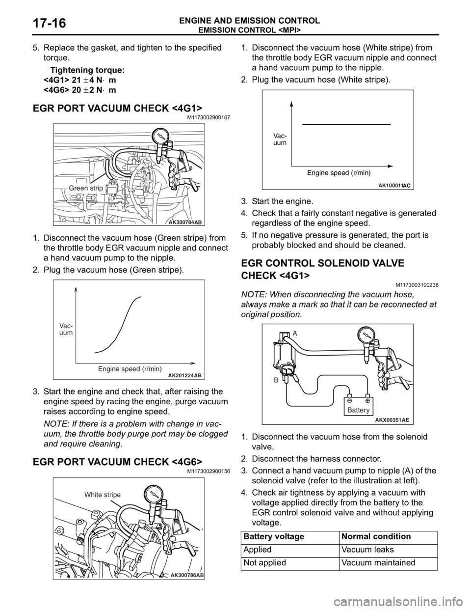
1.Disco nnect the vacu um ho se (Green stripe) from
th e t h ro tt le b o d y EGR va cuu m ni pp le an d co nn ec t
a hand vacu um p u mp to the nipple.
2.Plu g the vacuum hose (Gree n stripe).
AK201224AB
Vac-
uum
Engine speed (r/min)
3.S t art the engin e and check t hat, af ter ra ising th e
engine spe ed by ra cin g the e ngine, p u rge vacuu m
raises according to engine speed.
NOTE: If ther e is a prob lem with change in vac-
uum, the t h rottle bod y p u rge port may be clo gged
an
d requ ire clean ing.
EGR PORT VA CUUM CHECK <4G6>M1173 0029 0015 6
AK300786AB
White stripe
1.Disco nnect the vacu um h o se (W hite strip e ) from
th e t h ro tt le b o d y EGR va cuu m ni pp le an d co nn ec t
a hand vacuum p u mp to the nipple.
2.Plug the vacuum hose (White stripe).
AK100011AC
Vac-
uum
Engine speed (r/min)
3.S t art the engine.
4.Check that a fairly const a nt n egative is gene rated
re gardle s s of the engine sp eed.
5.If no neg ative pressur e is genera t ed, th e port is
p r obably blocked an d sh ould be cleane d.
EGR CONTROL SOLENOID VA L V E
CHECK <
4 G1 >
M1173 0031 0023 8
NOTE: Whe n discon nect i ng th e va cuum hose,
always make a mark so th at it can be reconnected at
original p o sition.
AKX00351
A
B
AE
Battery
1. Disco nnect the vacu um h o se f r om th e solenoid
valve.
2.Disco nnect the ha rness connector .
3.Con nect a ha nd vacu um pump to nipp le (A) of the
solen o id valve (ref e r to th e ill ust r ation at le f t ).
4.Check a i r tightness b y ap plying a vacuum with
volt age applied d i rectly from t he batt e ry to the
EGR cont rol solen o id valve and withou t applyin g
volt age .
Battery voltageNormal condition
AppliedVa c u u m l e a k s
Not appliedVacuum maintained
Page 135 of 800

SERVICE SPECIFICATIONS
FRONT AXLE26-3
SERVICE SPECIFICATIONS
M1261000300675
ItemStandard valueLimit
Wheel bearing axial play mm−0.05
Hub starting torque N⋅m−1.8
Protruding length of stabilizer bar mounting bolt mm22 ± 1.5−
Setting of TJ boot length mm1300-RH, 1600-A/T-RH85 ± 3−
1300-LH, 1600-M/T,
1600-A/T-LH, 200090 ± 3−
Opening dimension of the
special tool (MB991561) mmWhen the BJ boot band
(small) is crimped2.9−
When the BJ boot band
(large) is crimped2.9 −
Crimped width of the BJ boot band mm2.4 − 2.8−
LUBRICANTS
M1261000400735
ItemSpecified lubricantQuantity
TJ boot greaseRepair kit grease1300-LH, 1600-LH,
2000-LH120 ± 10 g
1300-RH, 1600-A/T-RH11 0 ± 10 g
1600-M/T-RH, 2000-A/T-RH120 ± 10 g
2000-M/T-RH105 ± 10 g
BJ boot greaseRepair kit grease95 ± 10 g
Page 137 of 800
SPECIA L T OOLS
FRONT AXLE26-5
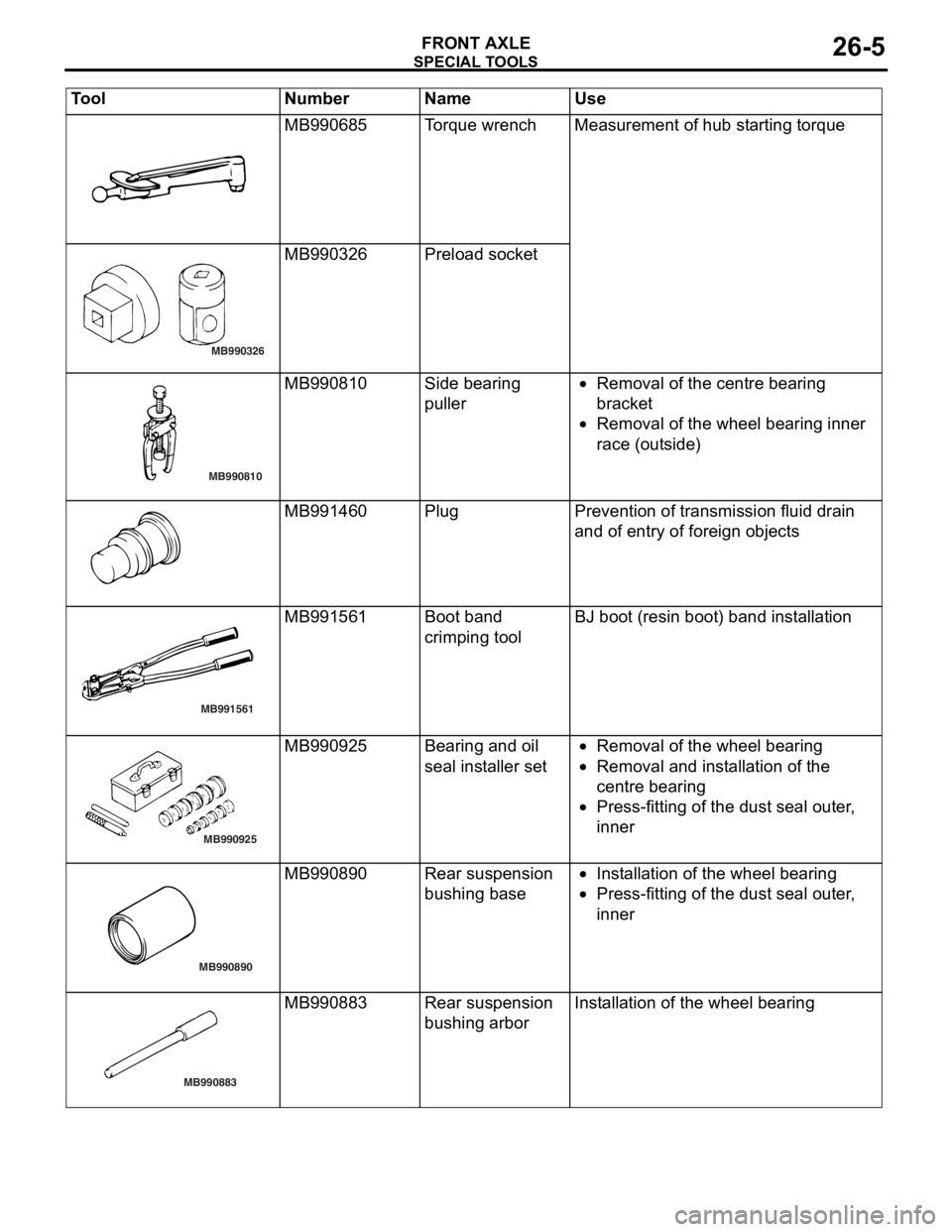
MB990685To rqu e wrenchMeas urement o f hub st arting torque
MB990326
MB990326 Prel oad socket
MB990810
MB990810Side be aring
puller•Removal of the centre b earing
bra
c ke t
•Removal of the whee l bea ring inner
r
a ce (o ut side )
MB991460PlugPreven tion of transmission fluid drain
and o
f entry of fore ign o b ject s
MB991561
MB991561Boot ban d
crimpin
g toolBJ boot (resin bo ot) ban d inst a lla tion
MB990925
MB990925Bearing and o il
seal
inst a lle r set•Removal of the whee l bea ring
•Removal and inst a lla tion o f the
centre
bearing
•Press-f i ttin g of th e dust se al ou ter ,
inner
MB990890
MB990890Rear suspension
bush
i ng b a se•In st allatio n of th e wheel bearing
•Press-f i ttin g of th e dust se al ou ter ,
inner
MB990883
MB990883Rear suspension
bush
i ng a r borInstallation of t he wheel bearing
Tool Nu mber Na me Use
Page 142 of 800
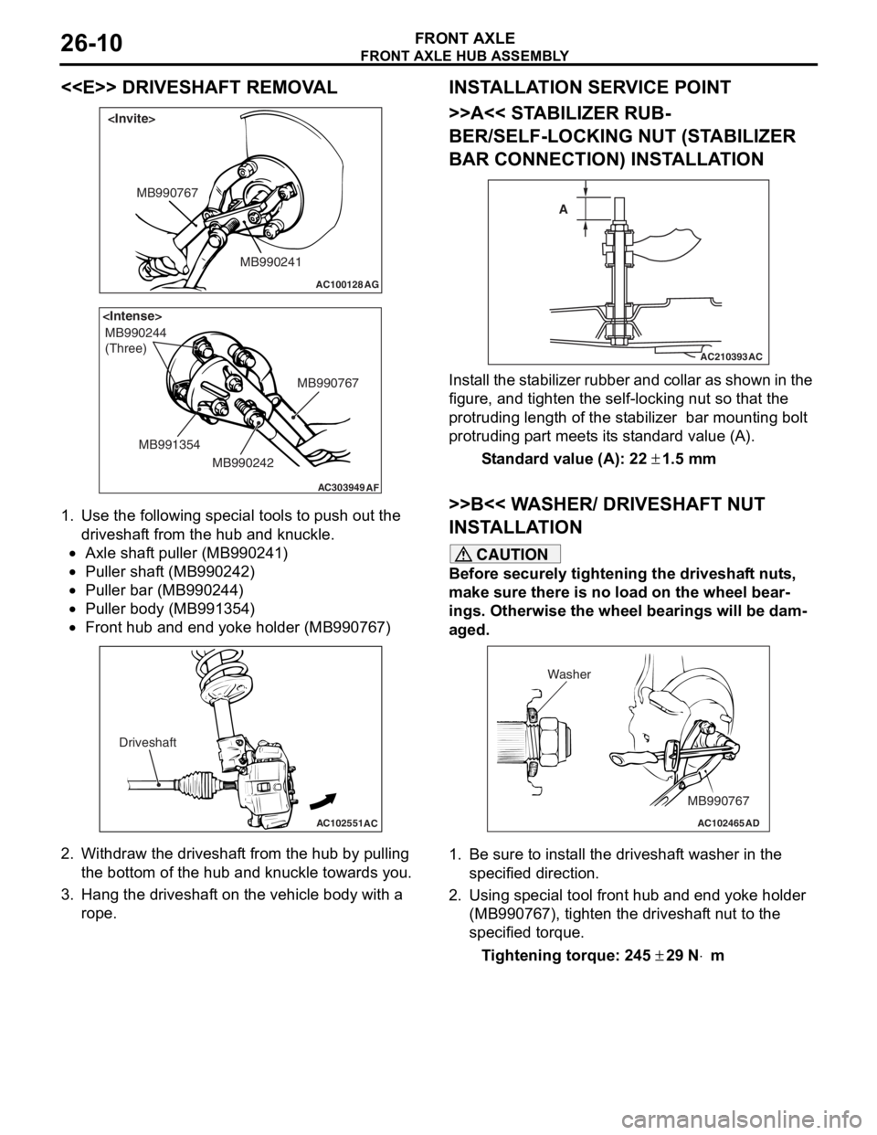
FRONT AXLE HUB ASSEMBLY
FRONT AXLE26-10
<
AC100128
MB990241
MB990767
AG
AC303949
MB990244
(Three)
MB990767
MB990242
MB991354
AF
1.
Use the fo llo wing special to ols to pu sh ou t the
driveshaf t from the hub an d kn uckle.
•Axle shaf t puller (MB9 90241 )
•Puller shaft (MB990 242)
•Puller bar (MB990 244)
•Puller body (MB99135 4)
•
AC102551
AC
Driveshaft
Front hub a nd end yoke holder (MB99076 7)
2.Withdraw th e driveshaf t from the hu b by pulling
th e botto m of the hub and knuckle towards you .
3.Hang the dr ive s haf t on the vehicle b ody with a
rope.
INST ALLA T ION SER VICE POINT
>>A<< STABILIZER RUB-
BER/SELF-LOCKING NUT (ST A BILIZER
BAR CONNECTION) INST
ALLA TION
AC210393AC
A
I
n st a ll the st a b ili zer rubb er an d coll ar as sho w n in t he
figure
, and t i ghte n the self-locking nut so tha t the
protruding length
of the st abilize r bar mount ing b o lt
protruding p
a rt meet s it s st and ard value (A).
St andard va lue (A): 22 ± 1.5 m m
>>B<< W A SHER/ DRIVESHAFT NUT
INST
ALLA TION
CAUTION
Before securely tightening the driveshaft nuts,
make sure there is no load on the wheel bear
-
ings. Otherwise the wheel bearings will be dam-
aged.
AC102465AD
MB990767
Washer
1. Be sure to install the driveshaft washer in the
specified direction.
2. Using special tool front hub and end yoke holder (MB990767), tighten the driveshaft nut to the
specified torque.
Tightening torque: 245 ± 29 N⋅m