lock MITSUBISHI LANCER IX 2006 Owners Manual
[x] Cancel search | Manufacturer: MITSUBISHI, Model Year: 2006, Model line: LANCER IX, Model: MITSUBISHI LANCER IX 2006Pages: 800, PDF Size: 45.03 MB
Page 328 of 800
KEYLESS ENTRY SYSTEM
BODY42-56
WHEN THE SPECIAL TOOL DIAGNOSIS
CODE CHECK HARNESS (MB991529) IS
USED
1. Check that the doors lock normally when the key is used.
2. Insert the ignition key.
CAUTION
Before connecting or disconnecting the earth,
turn the ignition switch to the "LOCK" (OFF)
position.
AC305133AB
Diagnosis
connector
MB991529Steering shaft
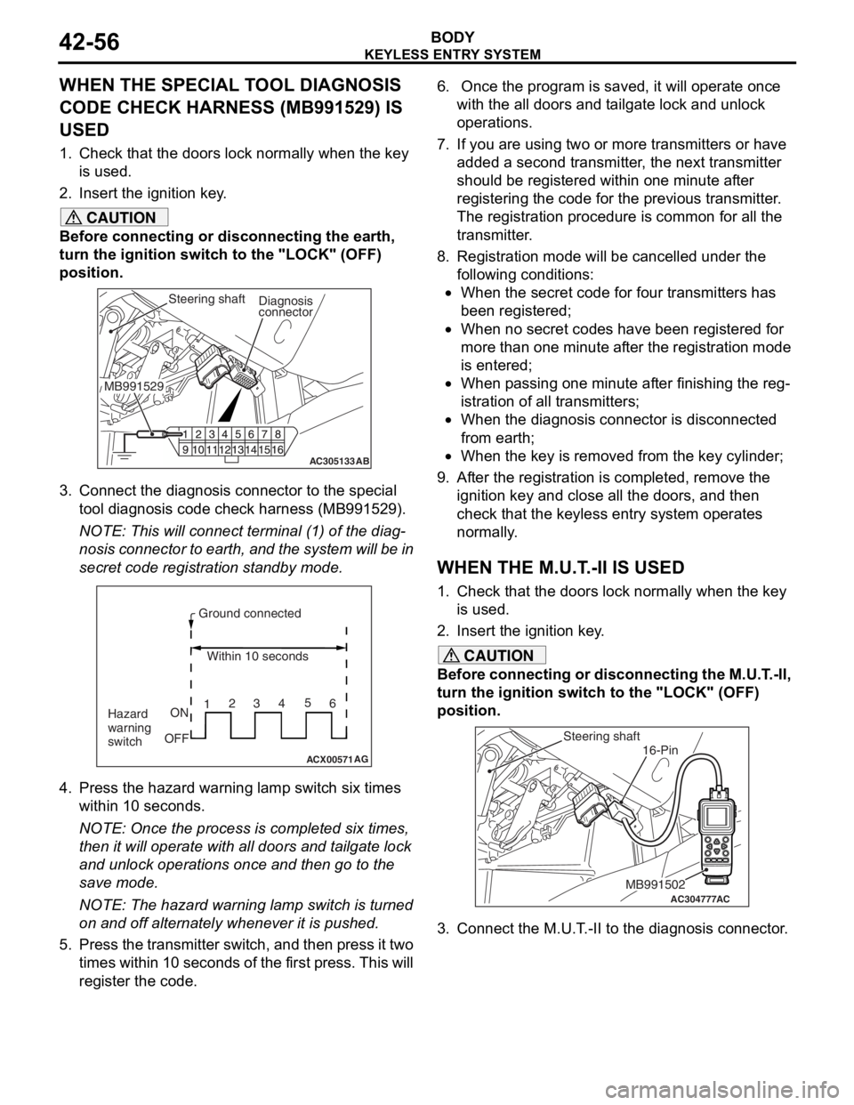
3. Connect the diagnosis connector to the special tool diagnosis code check harness (MB991529).
NOTE: This will connect terminal (1) of the diag-
nosis connector to earth, and the system will be in
secret code registration standby mode.
ACX00571
Ground connected
Within 10 seconds
Hazard
warning
switch ON
OFF 1
23
45
6
AG
4. Press the hazard warning lamp switch six times
within 10 seconds.
NOTE: Once the process is completed six times,
then it will operate with al l doors and tailgate lock
and unlock operations once and then go to the
save mode.
NOTE: The hazard warning lamp switch is turned
on and off alternately whenever it is pushed.
5. Press the transmitter switch, and then press it two times within 10 seconds of the first press. This will
register the code.
6. Once the program is saved, it will operate once
with the all doors and tailgate lock and unlock
operations.
7. If you are using two or more transmitters or have
added a second transmitter, the next transmitter
should be registered within one minute after
registering the code for the previous transmitter.
The registration procedure is common for all the
transmitter.
8. Registration mode will be cancelled under the following conditions:
•When the secret code for four transmitters has
been registered;
•When no secret codes have been registered for
more than one minute after the registration mode
is entered;
•When passing one minute after finishing the reg-
istration of all transmitters;
•When the diagnosis connector is disconnected
from earth;
•When the key is removed from the key cylinder;
9. After the registration is completed, remove the ignition key and close all the doors, and then
check that the keyless entry system operates
normally.
WHEN THE M.U.T.-II IS USED
1. Check that the doors lock normally when the key
is used.
2. Insert the ignition key.
CAUTION
Before connecting or disconnecting the M.U.T.-II,
turn the ignition switch to the "LOCK" (OFF)
position.
AC304777
Steering shaft
ACMB991502
16-Pin
3. Connect the M.U.T.-II to the diagnosis connector.
Page 329 of 800
ACX00571
M.U.T.-II connectedWithin 10 seconds
Hazard
warning
switch ON
OFF 1
23
45
6
AB
KEYLE SS ENTR Y SYSTEM
BOD Y42-57
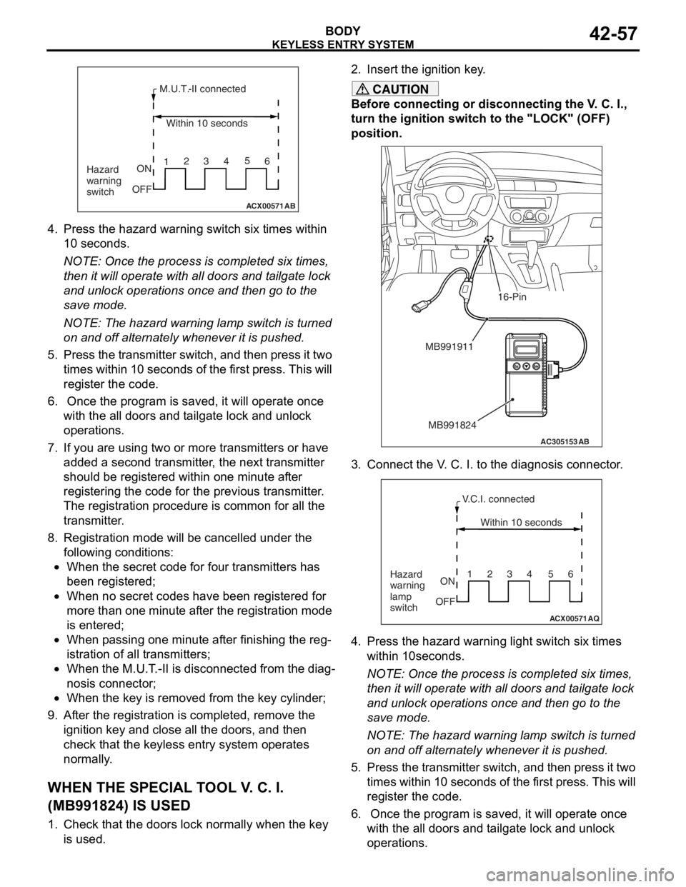
4.Press th e hazard warning switch six times within
10 seconds.
NOTE: Once th e process is comple ted six t i me s,
th
en it
will operate with al l do ors an d t a ilgate lock
an
d unlock opera t ions once and then go to th e
save
mode .
NOTE: The h a zard warnin g lamp switch is turned
on
and o ff alt e rnately when ever it is pushed.
5.Pre s s th e tr ansmitter switch, a nd then pre s s it two
t i mes within 10 second s of th e f i rst pre s s. This will
reg i st er the code.
6. Once the p r ogram is saved, it will opera t e once
wit h the a ll d oors a nd t a ilgate lock and unlo ck
op erations.
7.If you a r e using t w o or mo re transmitters or have
ad ded a second tra n smitter , the n e xt tra n smitter
should be re gistered within o ne minute af ter
reg i st ering the code fo r the pre v io us tra n smitter .
Th e registration pr oced ure is co mmo n for a ll th e
tra n smitter .
8.Registra tion mode will be ca ncelled under the
fo llowing condit i ons:
•When the secr et co de for fo ur transmitters has
bee
n registere d ;
•When no secre t cod e s h a ve b een re gist ered fo r
more tha
n one minute af ter the registration mode
is ente
r ed;
•When p a ssing o ne minute af ter fin i sh ing t he reg-
istration of all t r ansmitte rs;
•When the M.U.T . -II is d i sconne cted from th e dia g-
nosis connecto r;
•When the key is re moved fro m the key cylin der;
9.Af ter the registration is completed, remove the
ignition key a nd close all the d oors, and th en
check tha t the keyless entry syste m op erates
no rmally .
WH EN THE SPECIAL T O OL V . C. I.
(
M B991824) I S USED
1.Check t hat the doors lock n o rmally wh en the key
is used.
2. In sert t he ig nition ke y .
CAUTION
Before connecting or disconnecting the V. C. I.,
turn the ignition switch to the "LOCK" (OFF)
position.
AC305153AB
MB991911
MB991824
16-Pin
3. Connect the V. C. I. to the diagnosis connector.
ACX00571
Within 10 seconds
Hazard
warning
lamp
switch ON
OFF 1234 56
AQ
V.C.I. connected
4. Press the hazard warning
light switch six times
within 10seconds.
NOTE: Once the process is completed six times,
then it will operate with all doors and tailgate lock
and unlock operations once and then go to the
save mode.
NOTE: The hazard warning lamp switch is turned
on and off alternately whenever it is pushed.
5. Press the transmitter switch, and then press it two times within 10 seconds of the first press. This will
register the code.
6. Once the program is saved, it will operate once with the all doors and tailgate lock and unlock
operations.
Page 377 of 800
DOOR MIRROR
EXTERIOR51-45
STEP 2. Connector check: C-212 junction block
connector
AC304913
21716151718
201912345
623 222425282627981011141213
Connector: C-212
Harness side
AB
Junction block (Front view)
Q: Is t h e che c k r esu lt n o rmal?
YES : Intermittent malfun ctio n (Refer to GROUP
00
− Ho w to Cope wit h Intermitte nt
Ma
lfunction
P.00-5).
NO : Repa ir th e defective connector .
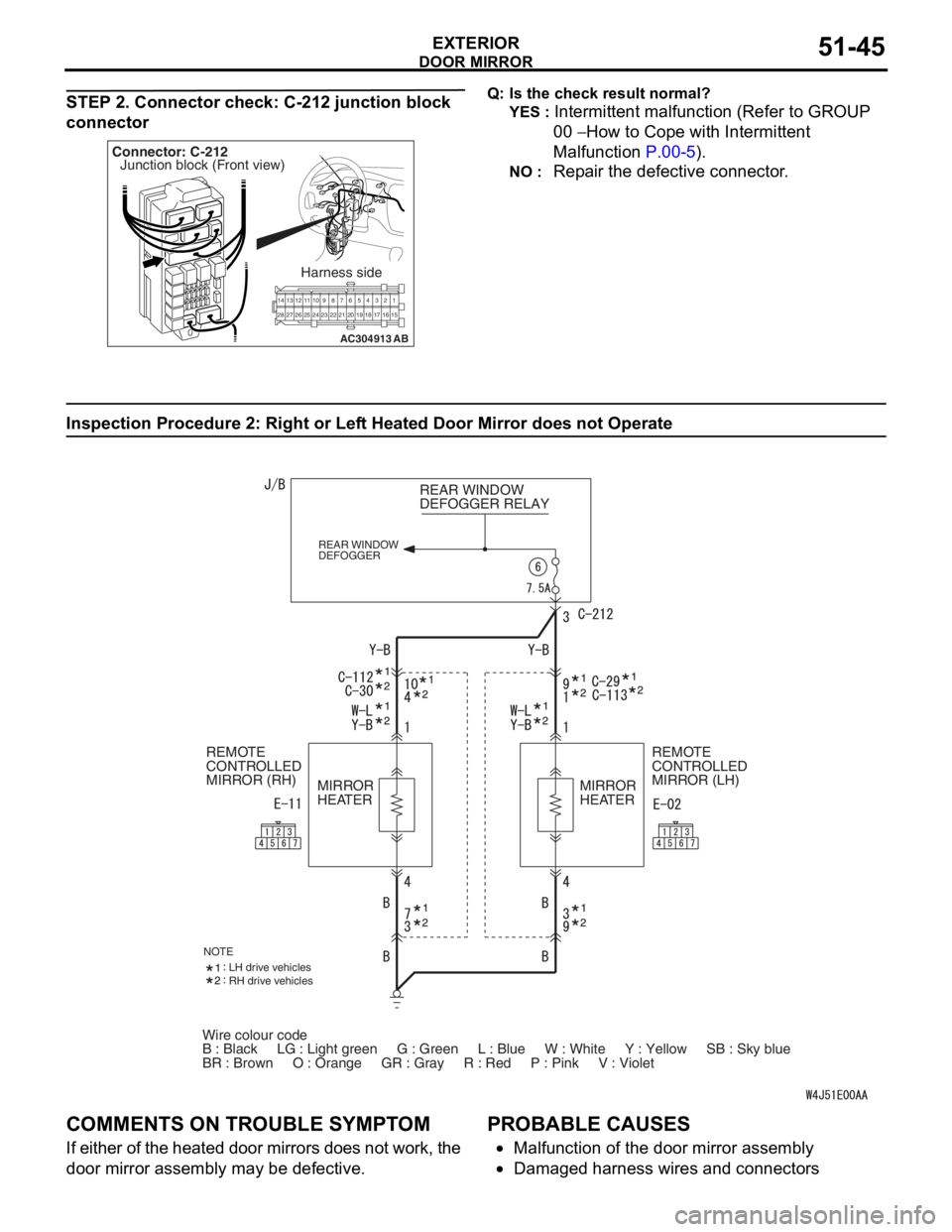
Inspection Procedure 2 : Ri ght or Lef t Hea t ed Door Mirror does not Operate
Wire colour code
B : Black LG : Light green G : Green L : Blue W : White \
Y : Yellow SB : Sky blue
BR : Brown O : Orange GR : Gray R : Red P : Pink V :\
Violet REAR WINDOW
DEFOGGER RELAY
REAR WINDOW
DEFOGGER
REMOTE
CONTROLLED
MIRROR (LH)
REMOTE
CONTROLLED
MIRROR (RH)
MIRROR
HEATER MIRROR
HEATER
NOTELH drive vehicles
RH drive vehicles
COMM
ENT S ON TROUBL E SYMPT O M
If eit her of t he hea ted d oor mirrors does n o t work, the
door mirror a
sse mbly may b e defe c tive.
PROBABLE CAUSES
•Malfunctio n of th e door mirro r assemb ly
•Damaged ha rness wires and con necto rs
Page 379 of 800
DOOR MIRROR
EXTERIOR51-47
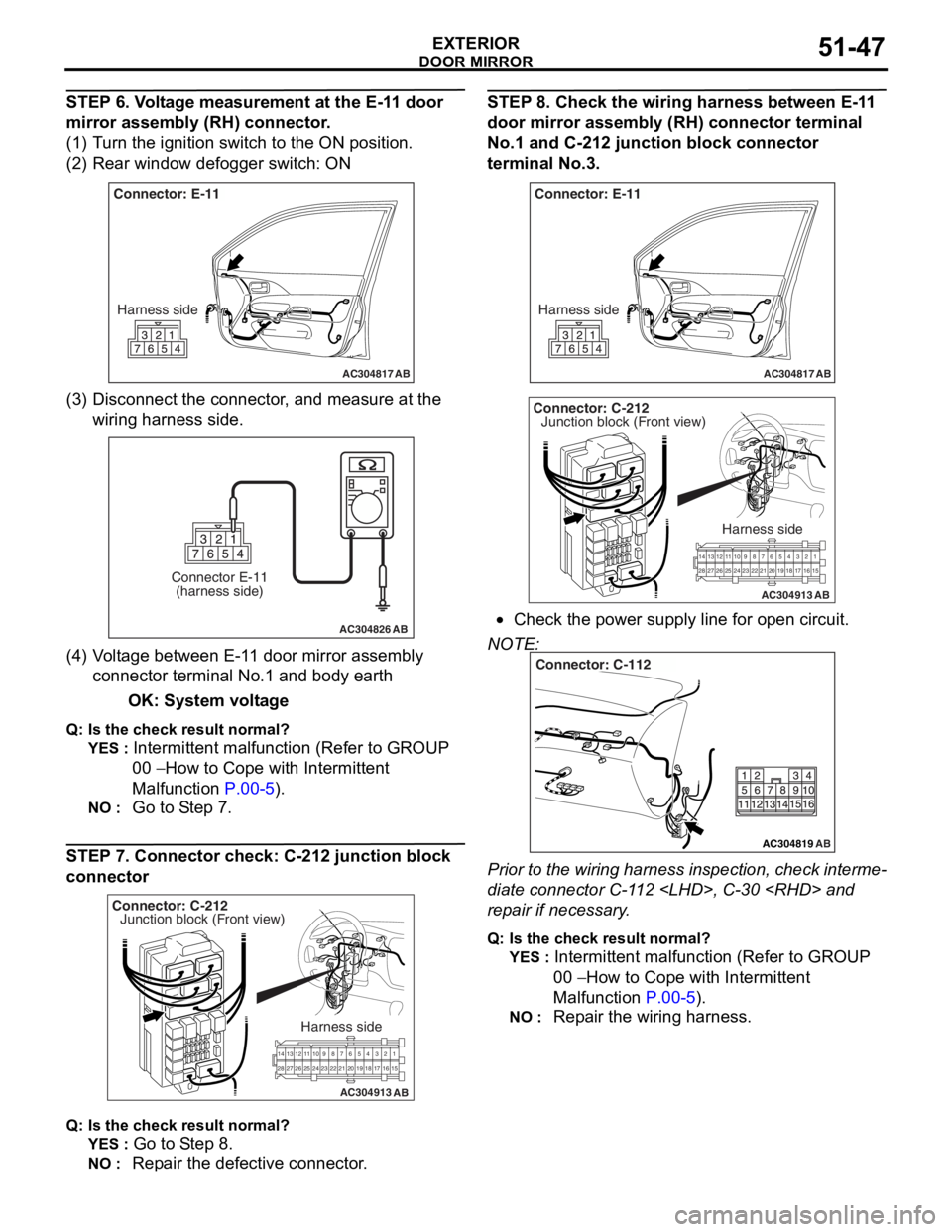
STEP 6. Voltage measurement at the E-11 door
mirror assembly (RH) connector.
(1) Turn the ignition switch to the ON position.
(2) Rear window defogger switch: ON
AC304817
Connector: E-11Harness side
AB
(3) D isconn ect t he co nnector , an d me asure at the
wiring harn e ss side.
AC304826
Connector E-11(harness side)
AB
(4) V olt a g e between E-1 1 door mirror assembly
co nnector termina l No.1 a nd bod y ea rth
OK: System vo lt age
Q: Is the check result normal?
YES : Intermittent ma lfun ctio n (Refer to GROUP
00
− Ho w t o Cope wit h Intermitte nt
Malfunction
P.00-5).
NO : Go to S t ep 7.
STEP 7. Co nnector ch eck: C-212 junction block
connecto
r
AC304913
21716151718
201912345
623 222425282627981011141213
Connector: C-212
Harness side
AB
Junction block (Front view)
Q : Is the check result normal?
YES : Go to S t ep 8.
NO : Repa ir the defective connector .
STEP 8 . Check the wiring harness b e twee n E-1 1
door mirror assem
bly (RH) conne ctor terminal
No.
1 and C-21 2 junctio n block connec tor
terminal No.3
.
AC304817
Connector: E-11
Harness side
AB
AC304913
21716151718
201912345
623 222425282627981011141213
Connector: C-212
Harness side
AB
Junction block (Front view)
•Check th e power supply line fo r open circuit.
NOTE:
AC304819
Connector: C-112
AB
Prior to the wiring harness insp ection, check interme-
diate connector C-1 1 2
rep
a ir if necessary .
Q:Is t h e che c k r esu lt n o rmal?
YES : Intermittent malfun ctio n (Refer to GROUP
00
− Ho w to Cope wit h Intermitte nt
Ma
lfunction
P.00-5).
NO : Repa ir th e wirin g harne ss.
Page 381 of 800
DOOR MIRROR
EXTERIOR51-49
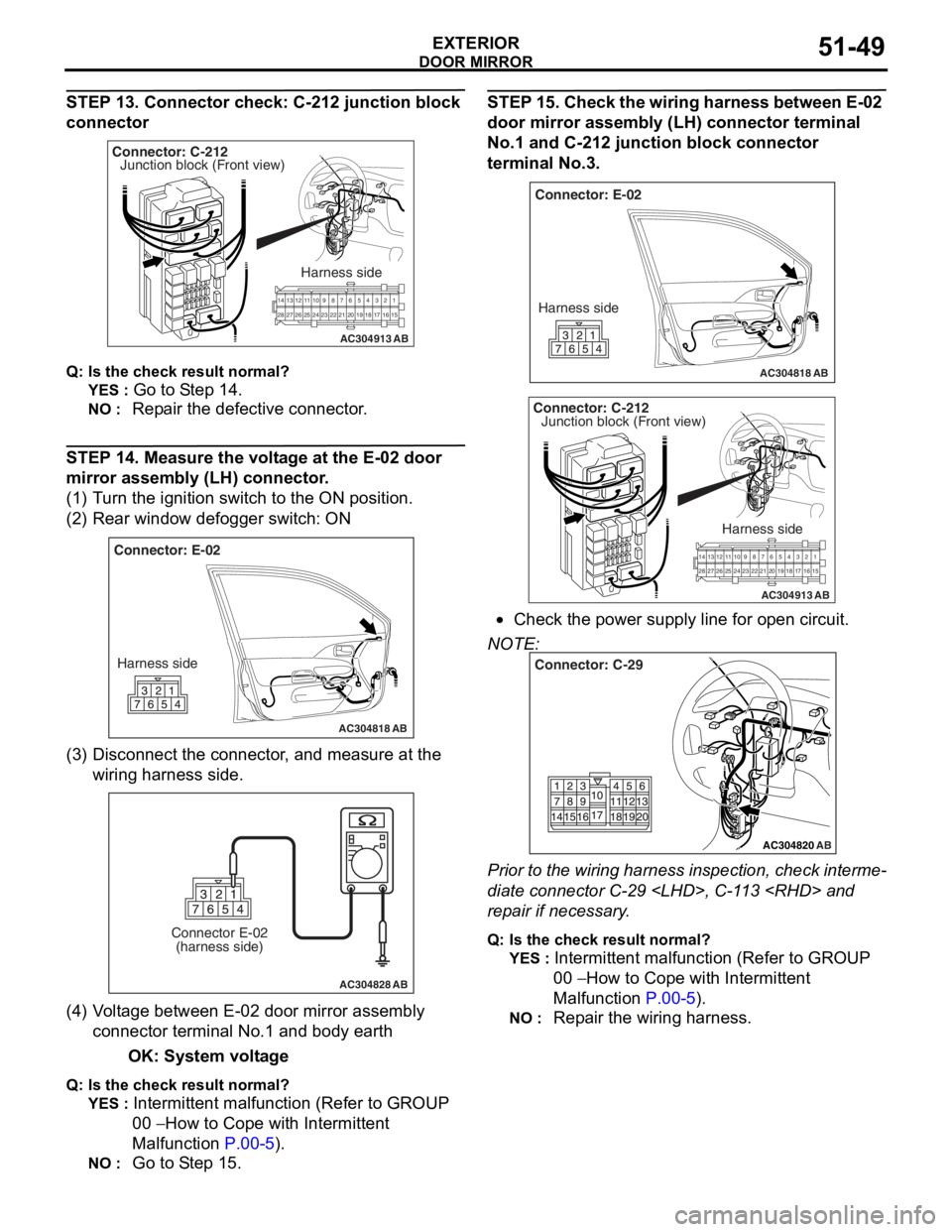
STEP 13. Connector check: C-212 junction block
connector
AC304913
21716151718
201912345
623 222425282627981011141213
Connector: C-212
Harness side
AB
Junction block (Front view)
Q : Is the check result normal?
YES : Go to S t ep 14 .
NO : Repa ir the defective connector .
STEP 14 . Me asure the volt age at the E-02 door
mirror a
ssembl y (LH) conne ctor .
(1)T urn t he ig nition switch to the ON positio n.
(2)R ear win dow defo gger switch : ON
AC304818
Connector: E-02
Harness side
AB
(3) D isconn ect t he co nnector , an d me asure at the
wiring harn e ss side.
AC304828
Connector E-02(harness side)
AB
(4) V olt a g e between E-02 doo r mirror assembly
co nnector termina l No.1 a nd bod y ea rth
OK: System vo lt age
Q: Is the check result normal?
YES : Intermittent ma lfun ctio n (Refer to GROUP
00
− Ho w t o Cope wit h Intermitte nt
Malfunction
P.00-5).
NO : Go to S t ep 15 .
STEP 1 5 . Chec k the wiring ha rnes s betwe en E-02
door mirror assem
bly (LH) con nector termina l
No.
1 and C-21 2 junctio n block connec tor
terminal No.3
.
AC304818
Connector: E-02
Harness side
AB
AC304913
21 716151718
201912345
623 222425282627981011141213
Connector: C-212
Harness side
AB
Junction block (Front view)
•Check th e power supply line fo r open circuit.
NOTE:
AC304820
Connector: C-29
AB
Prior to the wiring harness insp ection, check interme-
diate connector C-29
rep
a ir if necessary .
Q:Is t h e che c k r esu lt n o rmal?
YES : Intermittent malfun ctio n (Refer to GROUP
00
− Ho w to Cope wit h Intermitte nt
Ma
lfunction
P.00-5).
NO : Repa ir th e wirin g harne ss.
Page 394 of 800
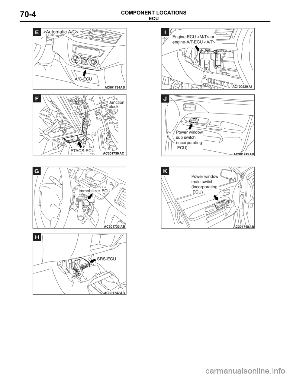
AC501784AB
E
A/C-ECU
AC301739AC
F
ETACS-ECU
Junction
block
AC301733AB
Immobilizer-ECU
G
AC301747AB
SRS-ECU
H
AC100229AI
Engine-ECU
engine-A/T-ECU I
AC301749AB
Power window
sub switch
(incorporating
ECU)
J
AC301748AB
Power window
main switch
(incorporating
ECU)
K
ECU
COMPONENT LOCA
TIONS70-4
Page 401 of 800
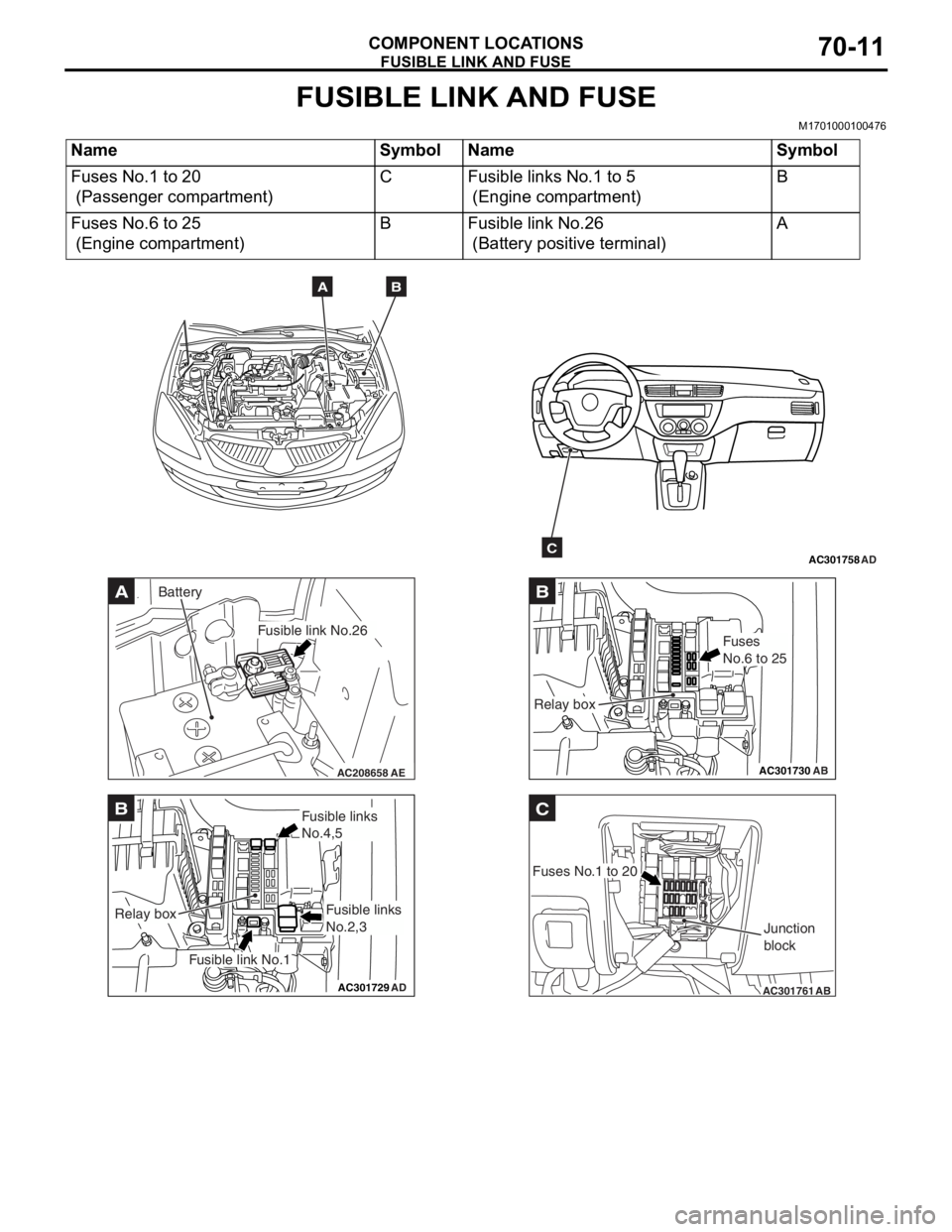
FUSIBLE LINK AND FUSE
COMPONENT LOCATIONS70-11
FUSIBLE LINK AND FUSE
M1701000100476
NameSymbolNameSymbol
Fuses No.1 to 20
(Passenger compartment)
CFusible links No.1 to 5
(Engine compartment)
B
Fuses No.6 to 25
(Engine compartment)
BFusible link No.26
(Battery positive terminal)
A
AC301758AD
AB
C
AC208658AE
A
Fusible link No.26
Battery
AC301729AD
B
Fusible link No.1
Relay box
Fusible links
No.4,5
Fusible links
No.2,3
AC301730
B
AB
Fuses
No.6 to 25
Relay box
AC301761
C
AB
Fuses No.1 to 20Junction
block
Page 407 of 800
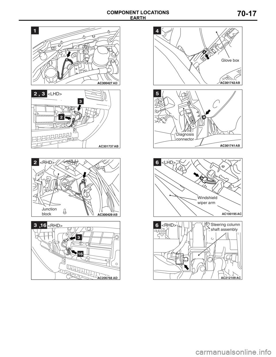
AC300427
1
AD
AC301737AB
2 3
,
2
3
AC300429 AB
2
Junction
block
AC206768 AD
3
16
,
3
16
AC301742 AB
4
Glove box
AC301741AB
5
Diagnosis
connector
AC100195
6
AC
Windshield
wiper arm
AC212109AC
6Steering column
shaft assembly
EARTH
COMPONENT LOCA
TIONS70-17
Page 409 of 800
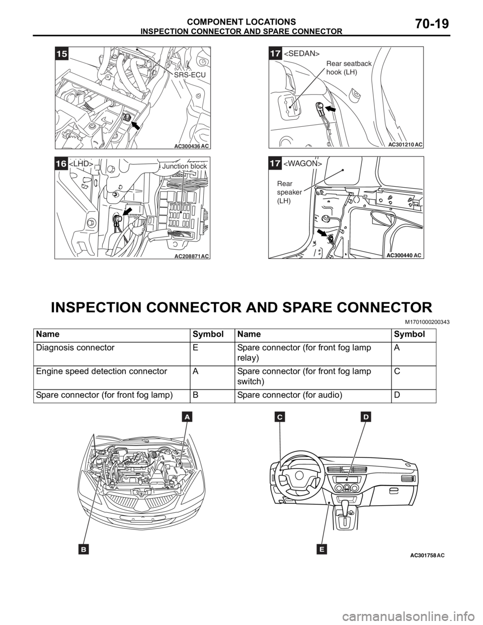
AC300436AC
15
SRS-ECU
AC208871AC
Junction block16
AC301210
17
AC
Rear seatback
hook (LH)
AC300440
17
AC
Rear
speaker
(LH)
INSPECTION CONN ECT O R AND SP ARE CONNEC T OR
COMPONENT LOCATIONS70-19
IN SPECTION CONNECT OR AND SP ARE CONNECT OR
M17010002 0034 3
NameSymbolNameSymbol
Diagnosis connectorESpare connector (for front fog lamp
relay)A
Engine speed detection connectorASpare connector (for front fog lamp
switch)C
Spare connector (for front fog lamp)BSpare connector (for audio)D
AC301758ACB
ADC
E
Page 438 of 800
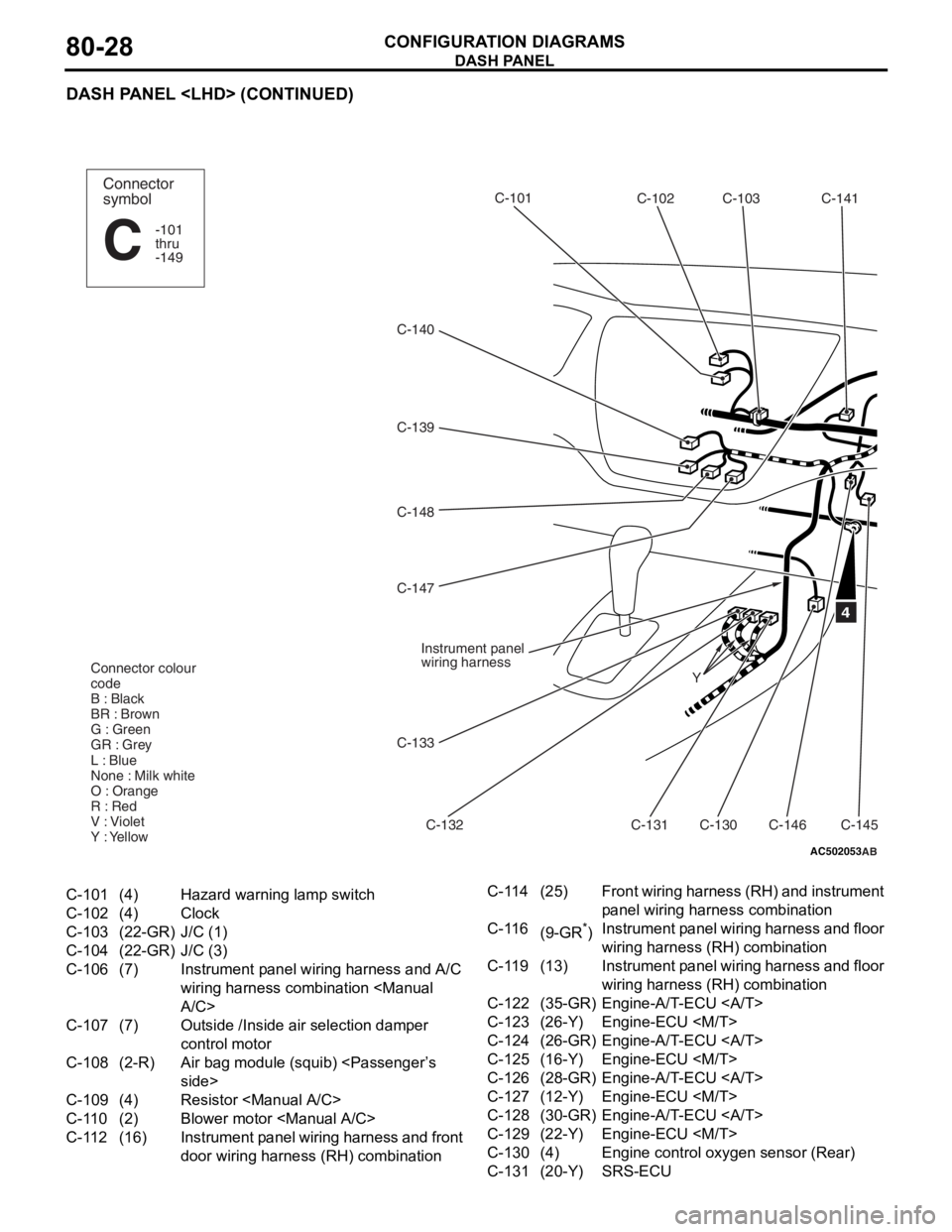
DASH PANEL
CONFIGURATION DIAGRAMS80-28
DASH PANEL
AC502053
C-140C-102
C-103
C-141
C-101
C-132
C-139
C-148
C-130
C-146C-145
Y
4
Connector
symbol
-101
thru
-149
C
Connector colour
code
B : Black
BR : Brown
G : Green
GR : Grey
L : Blue
None : Milk white
O : Orange
R : Red
V : Violet
Y : Yellow
Instrument panel
wiring harness
C-131
C-133
C-147
AB
C-101(4)Hazard warning lamp switch
C-102(4)Clock
C-103(22-GR)J/C (1)
C-104(22-GR)J/C (3)
C-106(7)Instrument panel wiring harness and A/C
wiring harness combination
C-107(7)Outside /Inside air selection damper
control motor
C-108(2-R)Air bag module (squib)
C-109(4)Resistor
C-110(2)Blower motor
C-112(16)Instrument panel wiring harness and front
door wiring harness (RH) combination
C-114(25)Front wiring harness (RH) and instrument
panel wiring har
ness combination
C-116(9-GR*)Instrument panel wiring harness and floor
wiring harness (RH) combination
C-119(13)Instrument panel wiring harness and floor
wiring harness (RH) combination
C-122(35-GR)Engine-A/T-ECU
C-123(26-Y)Engine-ECU
C-124(26-GR)Engine-A/T-ECU
C-125(16-Y)Engine-ECU
C-126(28-GR)Engine-A/T-ECU
C-127(12-Y)Engine-ECU
C-128(30-GR)Engine-A/T-ECU
C-129(22-Y)Engine-ECU
C-130(4)Engine control oxygen sensor (Rear)
C-131(20-Y)SRS-ECU