lock MITSUBISHI LANCER IX 2006 Manual PDF
[x] Cancel search | Manufacturer: MITSUBISHI, Model Year: 2006, Model line: LANCER IX, Model: MITSUBISHI LANCER IX 2006Pages: 800, PDF Size: 45.03 MB
Page 276 of 800
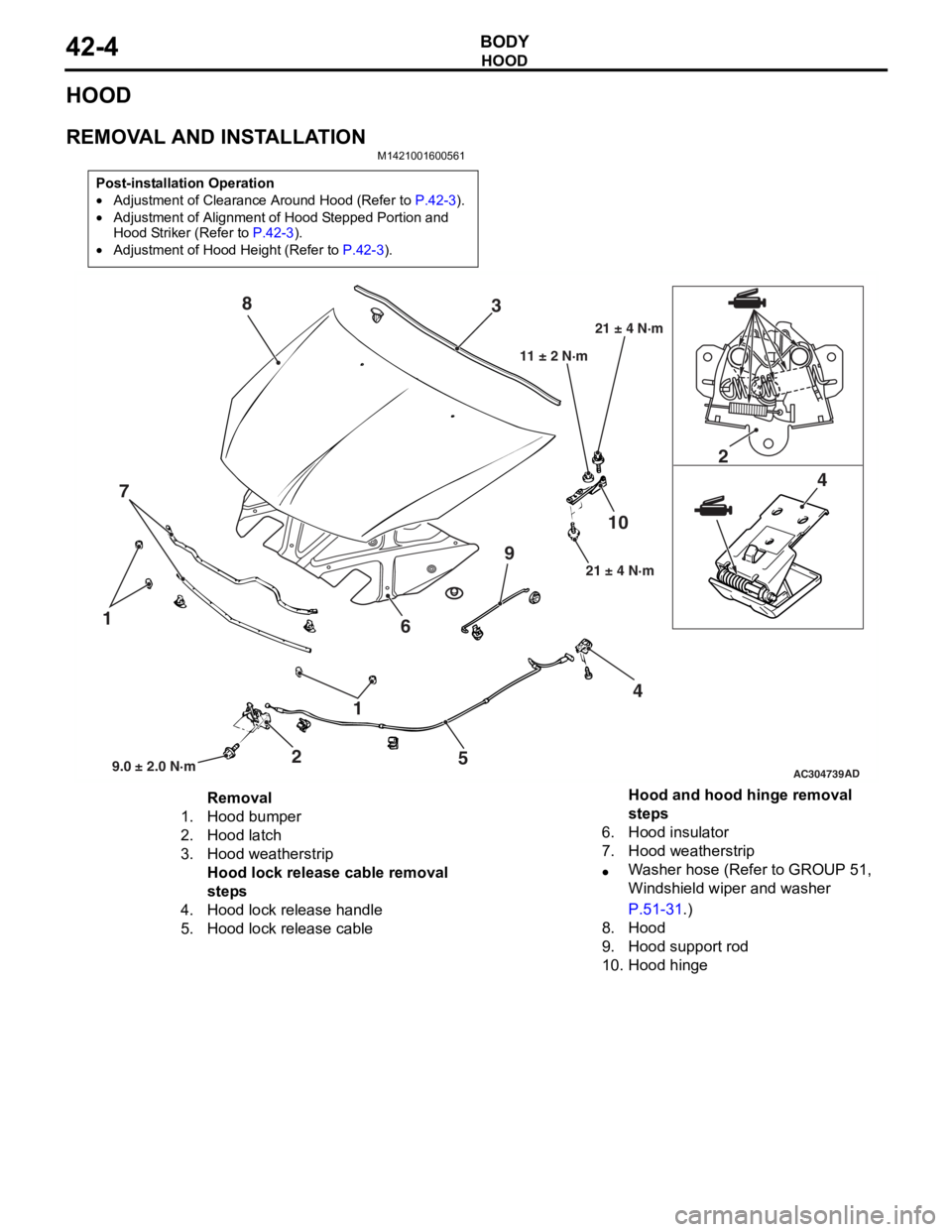
HOOD
BODY42-4
HOOD
REMOVAL AND INSTALLATION
M1421001600561
Post-installation Operation
•Adjustment of Clearance Around Hood (Refer to P.42-3).
•Adjustment of Alignment of Hood Stepped Portion and
Hood Striker (Refer to
P.42-3).
•Adjustment of Hood Height (Refer to P.42-3).
AC304739
1
1
2 2
4 4
5
6
7 3
8
910
AD9.0 ± 2.0 N·m 21 ± 4 N·m
11 ± 2 N·m
21 ± 4 N·m
Removal
1.Hood bumper
2.Hood latch
3.Hood weatherstrip
Hood lock release cable removal
steps
4.Hood lock release handle
5.Hood lock release cable
Hood and hood hinge removal
steps
6.Hood insulator
7.Hood weatherstrip
•Washer hose (Refer to GROUP 51,
Windshield wiper and washer
P.51-31.)
8.Hood
9.Hood support rod
10.Hood hinge
Page 280 of 800
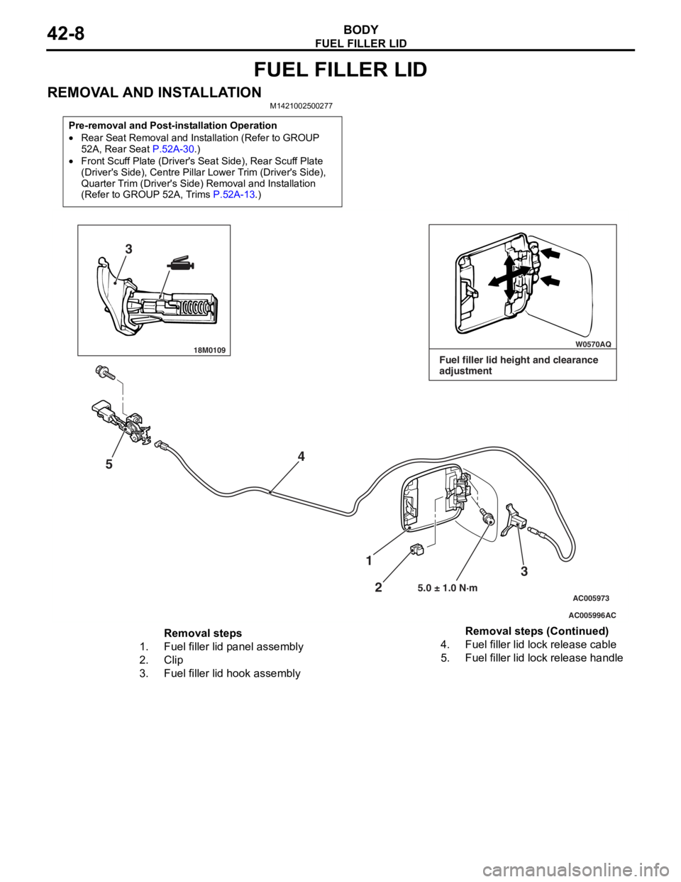
FUEL FILLER LID
BODY42-8
FUEL FILLER LID
REMOVAL AND INSTALLATIONM1421002500277
Pre-removal and Post-installation Operation
•Rear Seat Removal and Installation (Refer to GROUP
52A, Rear Seat
P.52A-30.)
•Front Scuff Plate (Driver's Seat Side), Rear Scuff Plate
(Driver's Side), Centre Pillar Lower Trim (Driver's Side),
Quarter Trim (Driver's Side) Removal and Installation
(Refer to GROUP 52A, Trims
P.52A-13.)
18M0109 W0570AQ
AC005996
AC005973
3
5 4
3
2
1
5.0 ± 1.0 N·m
AC
Fuel filler lid height and clearance
adjustment
Removal steps
1.Fuel filler lid panel assembly
2.Clip
3.Fuel filler lid hook assembly
4.Fuel filler lid lock release cable
5.Fuel filler lid lock release handle
Removal steps (Continued)
Page 283 of 800
WINDOW GLASS
BODY42-11
HANDLING OF AUTO WINDOW SEALER
Keep the sealant in a cool place, not exposed to the
direct rays of the sun. Do not place any heavy article
on the sealant nor press it, otherwise it will become
deformed. Avoid storing the sealant for more than 6
months, because it will lose its sealing effect.
BODY PINCH-WELD FLANGE SERVICING
Before servicing the body pinch-weld flange, remove
old adhesive completely. If the flange requires paint
-
ing, bake it after painting is completed.
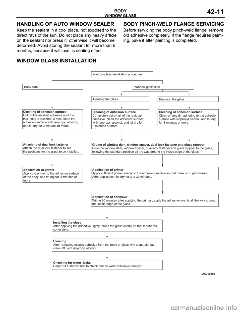
WINDOW GLASS INSTALLATION
Cleaning of adhesion surface
Cut off the residual adhesive until the
thickness is less than 2 mm. clean the
adhesion surface with isopropyl alcohol,
and let dry for 3 minutes or more.Cleaning of adhesion surface
Completely cut off all of the residual
adhesive. clean the adhesive surface
with isopropyl alcohol, and let dry for
3 minutes or more.Cleaning of adhesion surface
Clean off any dirt adhering to the adhesion
surface with isopropyl alcohol, and let dry
for 3 minutes or more.
Attaching of dual lock fastener
Attach the dual lock fastener to set
the positions for the glass to be installed.
Gluing of window dam, window spacer, dual lock fastener and glass stopper
Glue the window dam, window spacer, dual lock fastener and glass stopper to the glass,
following the standard position all the way around the inside edge of th\
e glass.
Application of primer
Apply the primer to the adhesion surface
of the body, and let dry for 3 minutes or
more.Application of primer
Apply sufficient primer evenly to the adhesion surface so that there is \
no patchiness.
After application, let dry for 3 to 30 minutes.
Application of adhesive
Within 30 minutes after applying the primer , apply the adhesive evenly \
all the way around
the inside edge of the glass.
Installing the glass
After applying the adhedive, lighty press the glass evenly so that it a\
dheres
completely.
Cleaning
After removing excess adhesive from the body or glass with a spatula, et\
c.
clean off with isopropyl alcohol.
Checking for water leaks
Carry out a shower test to check that no water will leaks through. Replace the glass
Reusing the glass
Window glass installation procedure
Body side
Window glass side
AC300393
Page 292 of 800
WINDOW GLASS
BODY42-20
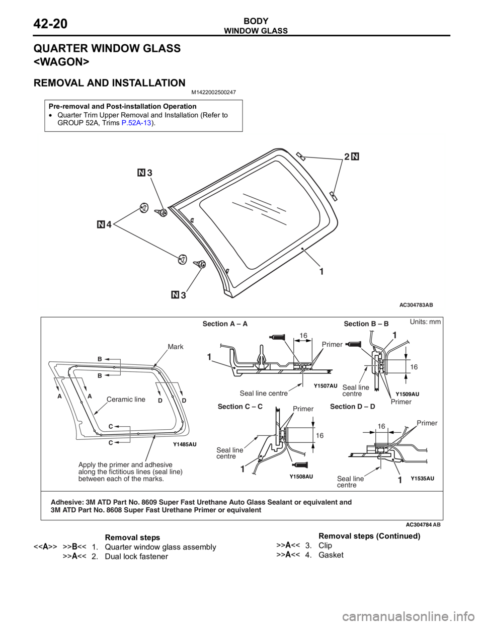
QUARTER WINDOW GLASS
REMOVAL AND INSTALLATION
M1422002500247
Pre-removal and Post-installation Operation
•Quarter Trim Upper Removal and Installation (Refer to
GROUP 52A, Trims
P.52A-13).
AC304783
N
N
N
12
3
N3
4
AB
Y1509AU
Y1508AU
Y1507AU
Y1485AU
Y1535AU
AC304784
AA B B
DD
C
C
Mark
Apply the primer and adhesive
along the fictitious lines (seal line)
between each of the marks.
Adhesive: 3M ATD Part No. 8609 Super Fast Urethane Auto Glass Sealant or equivalent and
3M ATD Part No. 8608 Super Fast Urethane Primer or equivalent
1
1
1
Seal line centrePrimer
Section A – A Section B – BSeal line
centre
Primer
Section C – C Section D – D
Seal line
centre Primer
1Seal line
centre
Units: mm
Primer
16
16 1616
Ceramic line
AB
Removal steps
<>>>B<<1.Quarter window glass assembly
>>A<<2.Dual lock fastener
>>A<<3.Clip
>>A<<4.Gasket
Removal steps (Continued)
Page 294 of 800
WINDOW GLASS
BODY42-22
INSTALLATION SERVICE POINTS
>>A<< GASKET/CLIP/DUAL LOCK FAS-
TENER INSTALLATION
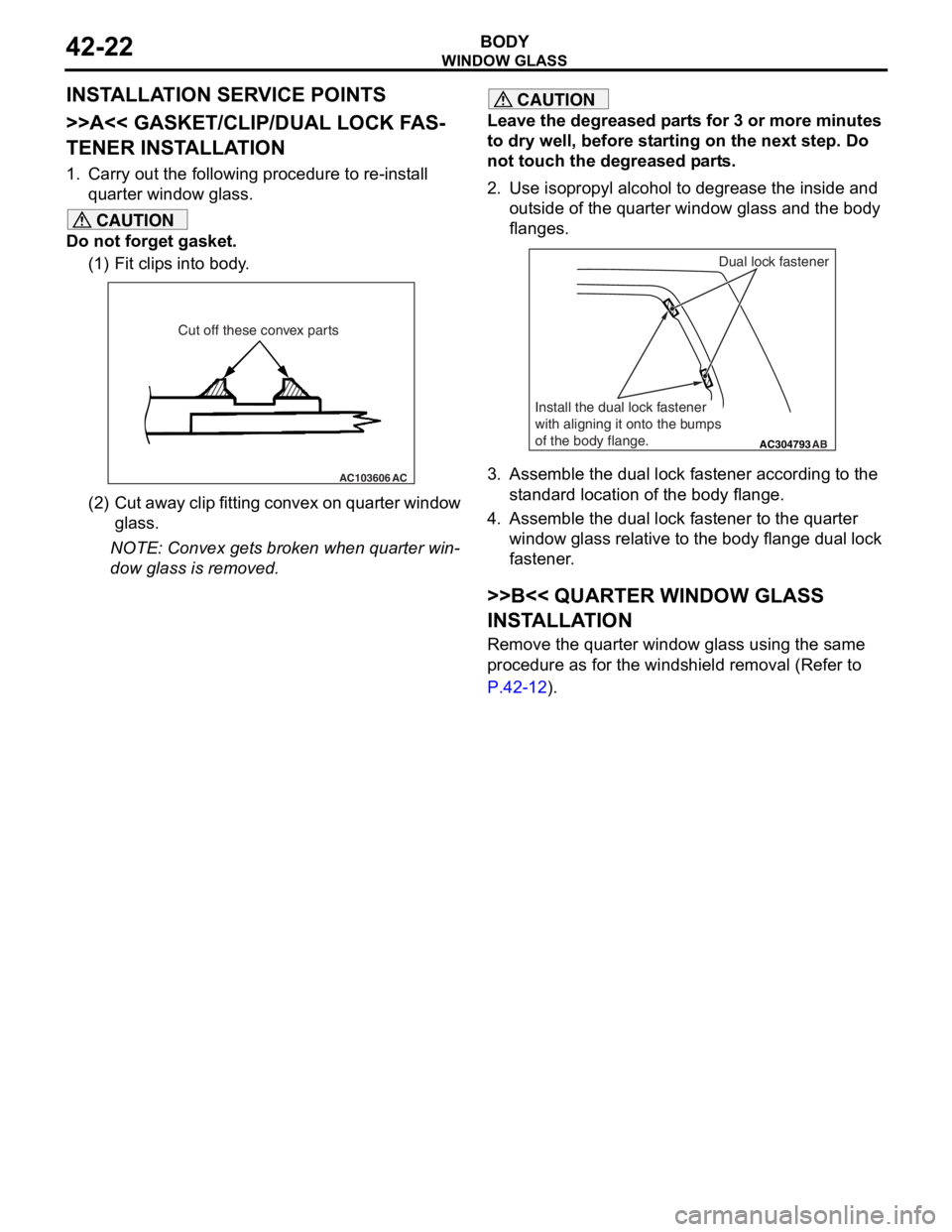
1. Carry out the following procedure to re-install quarter window glass.
CAUTION
Do not forget gasket.
(1) Fit clips into body.
AC103606 AC
Cut off these convex parts
(2) Cut away clip fitting convex on quarter window
glass.
NOTE: Convex gets broken when quarter win-
dow glass is removed.
CAUTION
Leave the degreased parts for 3 or more minutes
to dry well, before starting on the next step. Do
not touch the degreased parts.
2. Use isopropyl alcohol to degrease the inside and
outside of the quarter window glass and the body
flanges.
AC304793AB
Dual lock fastener
Install the dual lock fastener
with aligning it onto the bumps
of the body flange.
3. Assemble the dual lock fastener according to the standard location of the body flange.
4. Assemble the dual lock fastener to the quarter window glass relative to the body flange dual lock
fastener.
>>B<< QUARTER WINDOW GLASS
INSTALLATION
Remove the quarter window glass using the same
procedure as for the windshield removal (Refer to
P.42-12).
Page 296 of 800
Removal steps
1.Connecting the harness connector
<>>>B<<2.Tailgate window glass
>>A<<3.Window lower dam
>>A<<4.Window side dam
>>A<<5.Dual lock fastener
>>A<<6.Glass stopper
>>A<<7.Window spacer
WI ND OW GLAS S
BODY42-24
REMOVA L SER V ICE POINT
<> TA ILGA TE WINDOW GLASS
REMOV
A L
Remove the t a ilgate window g l ass using the same
proce
dure as for th e windshie l d (Refe r to
P.42-12).
INSTALLA T ION SER VICE POINTS
>>A<< WI NDOW SP ACER/GLASS ST OP-
PER/DUAL LOCK FA STENER/WINDOW
DAM INST
ALLA TION
CAUTION
Leave the degreased parts for 3 or more minutes
to dry well, before starting on the next step. Do
not touch the degreased parts.
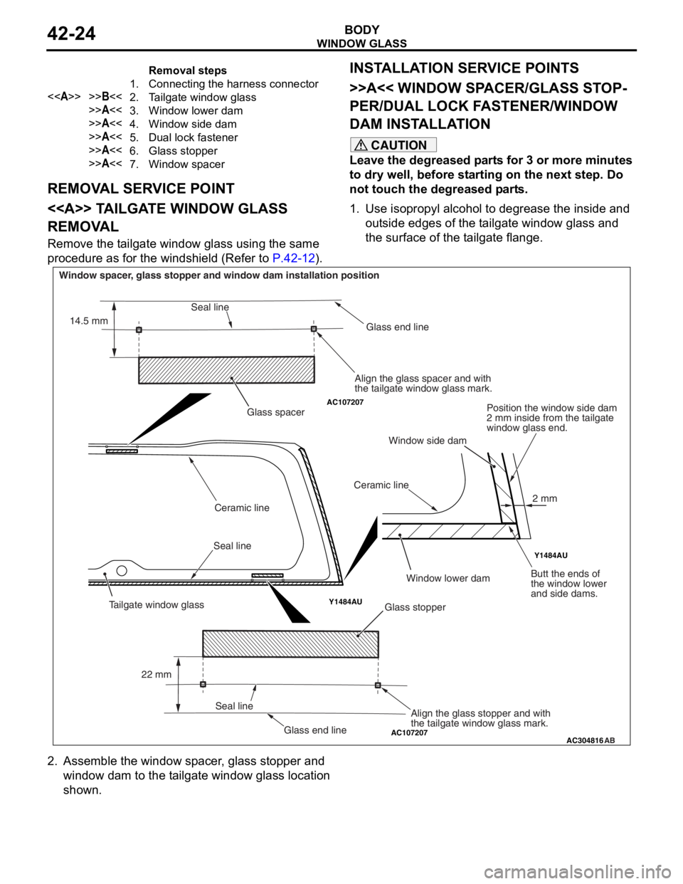
1. Use isopropyl alcohol to degrease the inside and outside edges of the tailgate window glass and
the surface of the tailgate flange.
AC107207
AC107207
Y1484AU Y1484AU
AC304816
AB
Glass stopper
Glass spacer
Seal line Ceramic line
Ceramic lineGlass end line
Glass end line
Window spacer, glass stopper and window dam installation position
Align the glass spacer and with
the tailgate window glass mark.Position the window side dam
2 mm inside from the tailgate
window glass end.
Butt the ends of
the window lower
and side dams.
Align the glass stopper and with
the tailgate window glass mark.
Seal line
Seal line
22 mm
14.5 mm
2 mm
Tailgate window glass
Window lower dam
Window side dam
2. Assemble the window spacer, glass stopper and
window dam to the tailgate window glass location
shown.
Page 297 of 800
AC304849AB
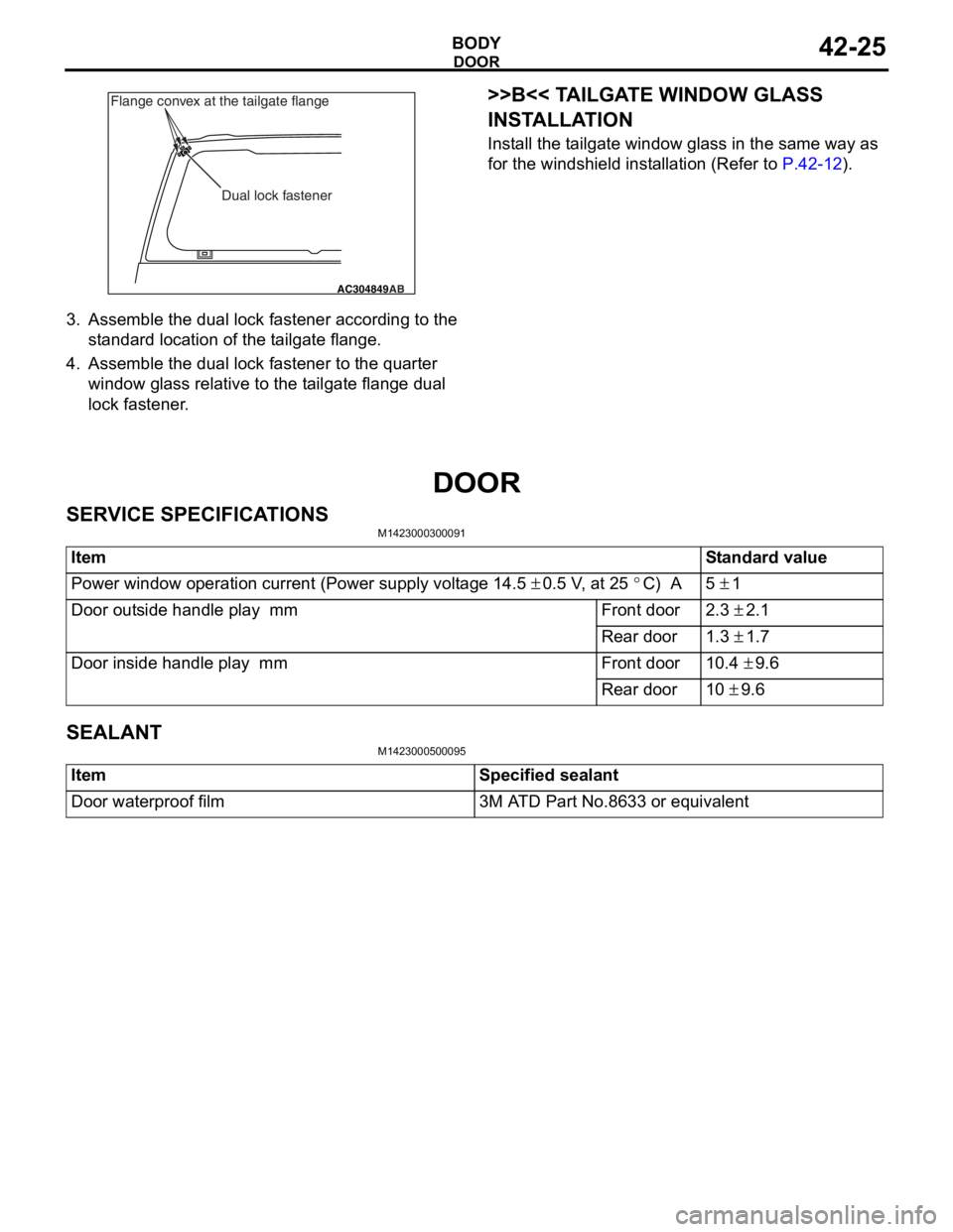
Dual lock fastener
Flange convex at the tailgate flange
DOOR
BO
D Y42-25
3.Assemble the dua l lo ck faste ner accord ing t o the
st a ndard loca tion of the t a ilgat e flan ge.
4.Assemble the dua l lo ck faste ner to t he qua rter
win dow gla ss relative to the t a ilgate flan ge dua l
lock fastener .
>>B<< TA ILGA TE WINDOW GLASS
INST
ALLA TION
Install the t a ilgat e window g l ass in the same wa y as
for the
windsh i eld inst a lla tion ( R ef er to
P.42-12).
DOOR
SER V ICE SPECIFICA T IONS
M14230003 0009 1
ItemStandard value
Power window operation current (Power supply voltage 14.5 ± 0.5 V, at 25 °C) A5 ± 1
Door outside handle play mmFront door2.3 ± 2.1
Rear door1.3 ± 1.7
Door inside handle play mmFront door10.4 ± 9.6
Rear door10 ± 9.6
SEALANT
M14230005 0009 5
ItemSpecified sealant
Door waterproof film3M ATD Part No.8633 or equivalent
Page 299 of 800
DOOR
BODY42-27
ON-VEHICLE SERVICE
DOOR FIT ADJUSTMENT
M1423001100175
CAUTION
•Attach protection tape to the fender and door
edges where the hinge is installed.
•Do not rotate special tool door adjusting
wrench (MB991164) with a torque of over 98
N
⋅m
AC000592
MB990900
or
MB991164
AB
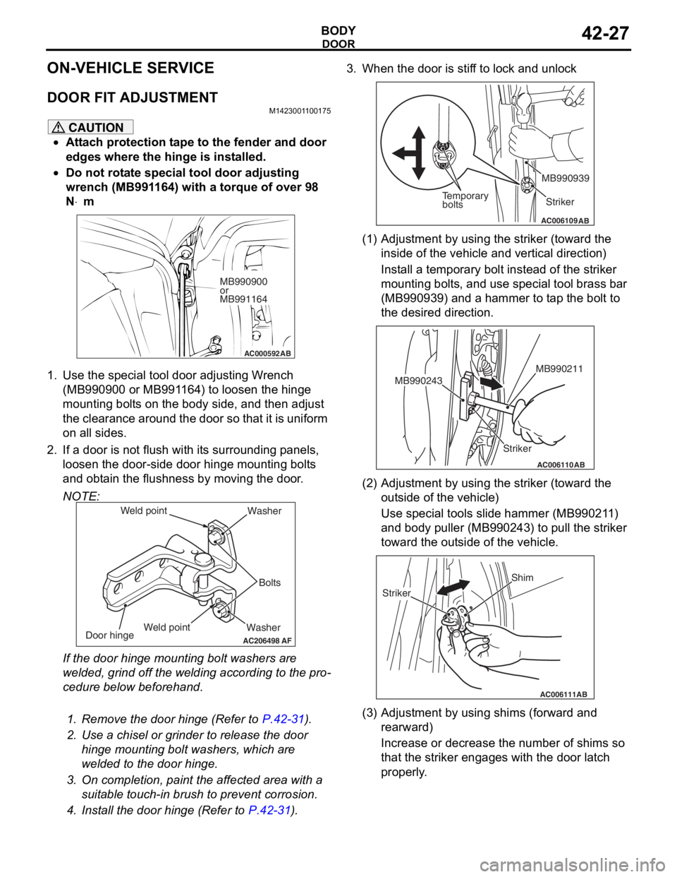
1. Use the special tool door adjusting Wrench (MB990900 or MB991164) to loosen the hinge
mounting bolts on the body side, and then adjust
the clearance around the door so that it is uniform
on all sides.
2. If a door is not flush with its surrounding panels,
loosen the door-side d oor hinge mounting bolts
and obtain the flushness by moving the door.
NOTE:
AC206498
Washer Bolts
Washer
Door hinge
AF
Weld point
Weld point
If the door hinge mounting bolt washers are
welded, grind off the welding according to the pro
-
cedure below beforehand.
.
1. Remove the door hinge (Refer to P.42-31).
2. Use a chisel or grinder to release the door
hinge mounting bolt washers, which are
welded to the door hinge.
3. On completion, paint the affected area with a suitable touch-in brush to prevent corrosion.
4. Install the door hinge (Refer to P.42-31).
3. When the door is stiff to lock and unlock
AC006109AB
Temporary
bolts Striker
MB990939
(1) Adjustment by using the striker (toward the
inside of the vehicle and vertical direction)
Install a temporary bolt instead of the striker
mounting bolts, and use special tool brass bar
(MB990939) and a hammer to tap the bolt to
the desired direction.
AC006110
Striker MB990211
MB990243
AB
(2) Adjustment by using the striker (toward the
outside of the vehicle)
Use special tools slide hammer (MB990211)
and body puller (MB990243) to pull the striker
toward the outside of the vehicle.
AC006111AB
Shim
Striker
(3) Adjustment by using shims (forward and rearward)
Increase or decrease the number of shims so
that the striker engages with the door latch
properly.
Page 301 of 800
DOOR
BODY42-29
3. If the operation current is outside the standard value, refer to GROUP 54B, Troubleshooting
P.54B-15, refer to GROUP 54C, Troubleshooting
P.54C-4.
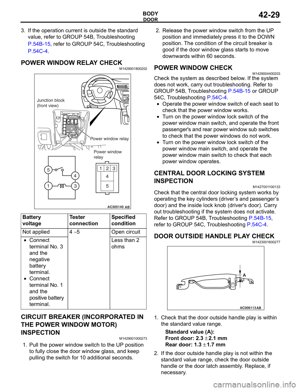
POWER WINDOW RELAY CHECKM1429001800202
AC305140
123
4
5
1 3
4
5
AB
Junction block
(front view)
Power window relayPower window
relay
Bat t ery
voltage
Teste r
co
nnectionSpecified
condition
Not applied4 − 5Ope n ci rcui t
•Connect
te
rmin al No. 3
an
d the
ne
gative
ba
ttery
te
rmin al.
•Connect
te
rmin al No. 1
an
d the
positive batt
e ry
te
rmin al.
Less than 2
ohms
CIRCUIT BREAKER (INCORPORA T ED IN
THE POW
E R W I NDOW MOT O R)
INSPECTION
M14290010 0027 3
1.Pull the p o wer windo w switch to th e UP position
to f u lly close the do or windo w g l ass, an d ke ep
pullin g the switch for 1 0 addition al secon d s.
2.Rele ase the power window switch from t he UP
position an d immediately pre ss it to t he DOW N
position. Th e con d ition of the circu i t brea ker is
goo d if t he doo r window g l ass st art s to mo ve
downward s with in 60 seconds.
POWER WI NDOW CHECKM14290044 0020 3
Check the system a s de scribed b e low . I f the system
does not work, car
r y out troublesh ootin g. Refer to
GROUP 54
B, T r ouble s hoo ting
P.54B-15 or GROUP
54C, T r oublesh ootin g P.54C-4.
•Operate the powe r wind ow switch of e a ch se at to
check that
the power window works.
•Tu rn o n the power wind ow lock switch of the
power wind
ow main swit ch, and ope rate the front
p
a ssenger's and rear power window su b switches
to check th
at the p o wer windo ws do n o t work.
•Tu rn o n the power wind ow lock switch of the
power
window main switch, and operate the
power
window main switch to check tha t each
power window
op erates.
CENTRAL DOOR LOCKING SYSTEM
INSPECTION
M142700 1 1 0013 3
Check that th e ce ntral door locking system wo rks by
op
er atin g th e key cylin de rs (d rive r ’ s an d p a sse n g e r ’ s
door) an
d the inside lock kno b (driver's door). Ca rry
out trou
bleshooting if the system does not activate.
Re
fer to GROUP 54B, T r ou bleshooting
P.54B-15,
refer to GROUP 54 C, T r o uble s hoo ting P.54C-4.
DOOR OUTSIDE HANDLE PL A Y CHECKM14230016 0027 7
AC006113
AB
A
1.Check t hat the door o u t s ide handle play is with in
th e st and ard va lue range.
St andard va lue (A):
Fron t door: 2.3 ± 2.1 m m
Rear door: 1.3 ± 1.7 mm
2. If the do or out side ha ndle play is not wit h in th e
st a ndard valu e rang e, ch eck the do or out side
h andle or the door latch assemb ly . Replace, if
ne c e ss a r y .
Page 308 of 800
DOOR
BODY42-36
DOOR HANDLE AND LATCH
REMOVAL AND INSTALLATION
M1423004600328
Pre-removal Operation
•Door Trim Removal (Refer to GROUP 52A, Door trim P.52A-17.)
Post-installation Operation
•Door Inside Handle Play Check (Refer to P.42-30.)
•Door Outside Handle Play Check (Refer to P.42-29.)
•Door Trim Installation (Refer to GROUP 52A, Door trim
P.52A-17.)
AC305110
5
5.0 ± 1.0 N·m
1
4
9
2
AB
4 5
2
3
8 7
5.0 ± 1.0 N·m
1
6
9
NN
89.0 ± 2.0 N·m 9.0 ± 2.0 N·m
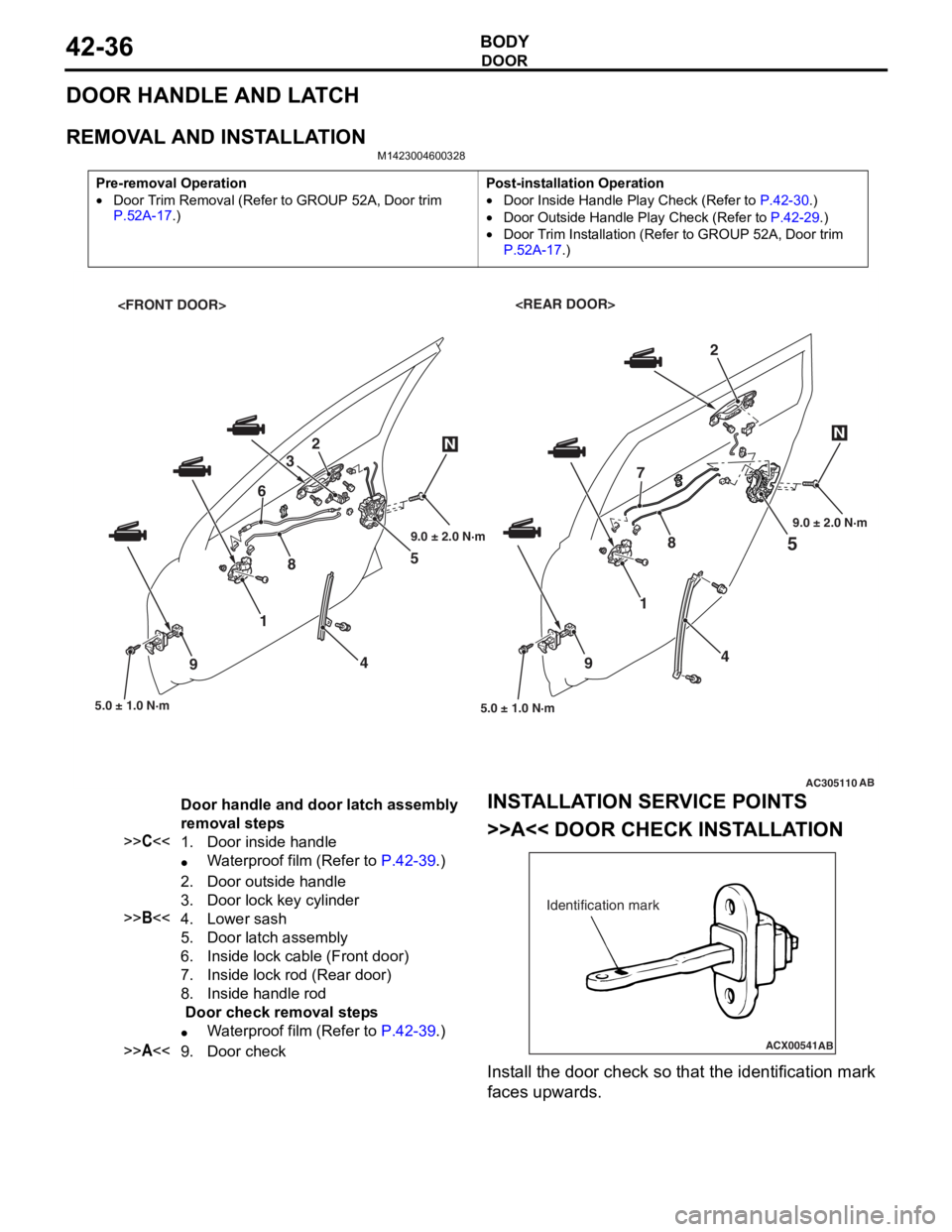
Door handle and door latch assembly
removal steps
>>C<<1.Door inside handle
•Waterproof film (Refer to P.42-39.)
2.Door outside handle
3.Door lock key cylinder
>>B<<4.Lower sash
5.Door latch assembly
6.Inside lock cable (Front door)
7.Inside lock rod (Rear door)
8.Inside handle rod
Door check removal steps
•Waterproof film (Refer to P.42-39.)
>>A<<9.Door check
INST
ALLA T ION SER VICE POINTS
>>A<< DOOR CHECK INST ALLA TION
ACX00541
Identification mark
AB
Install the d oor check so that th e ide n tification mark
faces upward
s .