air suspension MITSUBISHI LANCER IX 2006 Service Manual
[x] Cancel search | Manufacturer: MITSUBISHI, Model Year: 2006, Model line: LANCER IX, Model: MITSUBISHI LANCER IX 2006Pages: 800, PDF Size: 45.03 MB
Page 183 of 800

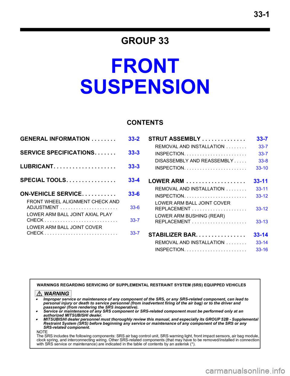
33-1
GROUP 33
FRONT
SUSPENSION
CONTENTS
GENERAL INFORMATIO N . . . . . . . .33-2
SERVICE SPECIFICATIONS . . . . . . .33-3
LUBRICANT . . . . . . . . . . . . . . . . . . . .33-3
SPECIAL TOOLS . . . . . . . . . . . . . . . .33-4
ON-VEHICLE SERVICE . . . . . . . . . . .33-6
FRONT WHEEL ALIGNMENT CHECK AND
ADJUSTMENT . . . . . . . . . . . . . . . . . . . . . . 33-6
LOWER ARM BALL JOINT AXIAL PLAY
CHECK . . . . . . . . . . . . . . . . . . . . . . . . . . . . 33-7
LOWER ARM BALL JOINT COVER
CHECK . . . . . . . . . . . . . . . . . . . . . . . . . . . . 33-7
STRUT ASSEMBLY . . . . . . . . . . . . . .33-7
REMOVAL AND INSTALLATION . . . . . . . . 33-7
INSPECTION. . . . . . . . . . . . . . . . . . . . . . . . 33-7
DISASSEMBLY AND REASSEMBLY . . . . . 33-8
INSPECTION. . . . . . . . . . . . . . . . . . . . . . . . 33-10
LOWER ARM . . . . . . . . . . . . . . . . . . .33-11
REMOVAL AND INSTALLATION . . . . . . . . 33-11
INSPECTION. . . . . . . . . . . . . . . . . . . . . . . . 33-12
LOWER ARM BALL JOINT COVER
REPLACEMENT . . . . . . . . . . . . . . . . . . . . . 33-12
LOWER ARM BUSHING (REAR)
REPLACEMENT . . . . . . . . . . . . . . . . . . . . . 33-13
STABILIZER BAR. . . . . . . . . . . . . . . .33-14
REMOVAL AND INSTALLATION . . . . . . . . 33-14
INSPECTION. . . . . . . . . . . . . . . . . . . . . . . . 33-16
WARNINGS REGARDING SERVICING OF SUPPLEMENTAL RESTRAINT SYSTEM (SRS) EQUIPPED VEHICLES
WARNING
•Improper service or maintenance of any component of the SRS, or any SRS-related component, can lead to
personal injury or death to service personnel (from inad vertent firing of the air bag) or to the driver and
paassenger (from rendering the SRS inoperative).
•Service or maintenance of any SRS component or SRS-related component must be performed only at an
authorized MITSUBISHI dealer.
•MITSUBISHI dealer personnel must thoroughly review this manual, and especially its GROUP 52B - Supplemental
Restraint System (SRS) before beginning any service or maintenance of any component of the SRS or any
SRS-related component.
NOTE
The SRS includes the following components: SRS air bag control unit, SRS warning light, front impact sensors, air bag module,
clock spring, and interconnecting wiring. Other SRS-related components (that may have to be removed/installed in connection
with SRS service or maintenance) are indicated in the table of contents by an asterisk (*).
Page 196 of 800

STABILIZER BAR
FRONT SUSPENSION33-14
STABILIZER BAR
REMOVAL AND INSTALLATIONM1332004000673
CAUTION
•Before removing the steering wheel and air bag module assembly, refer to GROUP 52B, Service
Precautions
P.52B-5 and Air Bag Module and Clock Spring P.52B-194. Also, put the front wheels in
straight-ahead position. Failure to do so may damage the SRS clock spring and render the SRS air
bag inoperative, which results serious driver injury.
•
Pre-removal Operation
•Steering Wheel and Air Bag Module Assembly Removal
(Comfort: refer to GROUP 37, Steering Wheel
P.37-17/Sport: refer to GROUP 37, Steering Wheel P.37-18).•Clock Spring Removal (Refer to GROUP 52B, Air Bag
Modules and Clock Spring P.52B-194).
•Centermember Removal (Ref er to GROUP 32, Engine
Roll Stopper, Centermember P.32-7).
•Front Exhaust Pipe Remova l (Refer to GROUP 15,
Exhaust Pipe and Main Muffler P.15-10).
Post-installation Operation
•Front Exhaust Pipe Installation (Refer to GROUP 15,
Exhaust Pipe and Main Muffler P.15-10).•Centermember Installation (Refer to GROUP 32, Engine
Roll Stopper, Centermember P.32-7).
•Clock Spring Installation (Refer to GROUP 52B, Air Bag
Modules and Clock Spring P.52B-194).
•Steering Wheel and Air Bag Module Assembly Installation
(Comfort: refer to GROUP 37, Steering Wheel
P.37-17/Sport: refer to GROUP 37, Steering Wheel P.37-18).•Check the dust covers for cracks or damage by pushing it
with your finger.
•Checking Steering Wheel Position with Wheels Straight
Ahead
•Front Wheel Alignment Check and Adjustment (Refer to P.33-6).
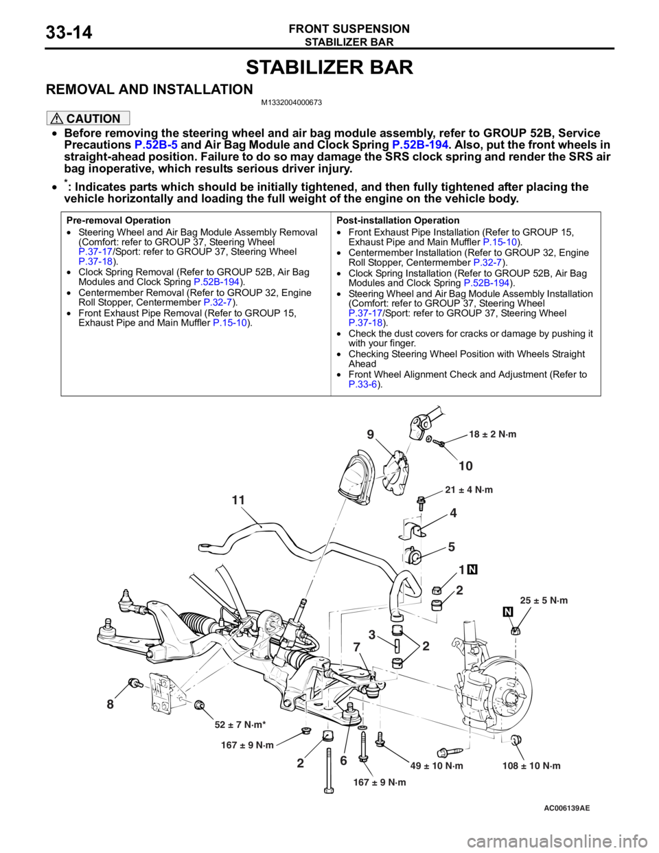
AC006139 AE
49 ± 10 N·m 108 ± 10 N·m
167 ± 9 N·m
167 ± 9 N·m
52 ± 7 N·m* 25 ± 5 N·m
21 ± 4 N·m
18 ± 2 N·m
10
9
4
5 1
2
2
3
7
6
2
11
8
*: Indicates parts which should be initially tightened, and then fully tightened after placing the
vehicle horizontally and loading the full weight of the engine on the vehicle body.