length MITSUBISHI LANCER IX 2006 Service Manual
[x] Cancel search | Manufacturer: MITSUBISHI, Model Year: 2006, Model line: LANCER IX, Model: MITSUBISHI LANCER IX 2006Pages: 800, PDF Size: 45.03 MB
Page 41 of 800
WATE R P U M P
ENGINE COOLING14-27
WAT E R P U M P
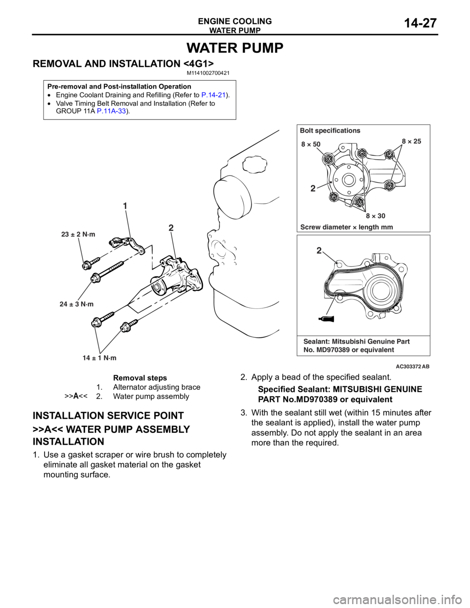
REMOVAL AND INSTALLATION <4G1>M1141002700421
Pre-removal and Post-installation Operation
•Engine Coolant Draining and Refilling (Refer to P.14-21).
•Valve Timing Belt Removal and Installation (Refer to
GROUP 11A P.11A-33).
AC303372
24 ± 3 N·m23 ± 2 N·m
14 ± 1 N·m
1 2
Bolt specifications
Screw diameter × length mm 8 × 50
8 × 308 × 25
AB
2
2
Sealant: Mitsubishi Genuine Part
No. MD970389 or equivalent
Removal steps
1.Alternator adjusting brace
>>A<<2.Water pump assembly
INST ALLA T ION SER VICE POINT
>>A<< WA TER PUMP ASSEMBL Y
INST
ALLA TION
1.Use a gaske t scraper o r wire brush to complet e ly
eliminate all gasket material o n the g a sket
mounting surface.
2. App l y a bead of the specified sealan t.
Specified Sealant: MITSUBISHI GENUINE
P
ART No.MD970 389 or eq uivalen t
3.With the sea l ant still wet (within 1 5 minutes af ter
th e se alant is applied), inst all the wa ter pump
a sse mbly . Do not a pply the sealant in an are a
more th an the required.
Page 42 of 800
WATE R P U M P
ENGINE COOLING14-28
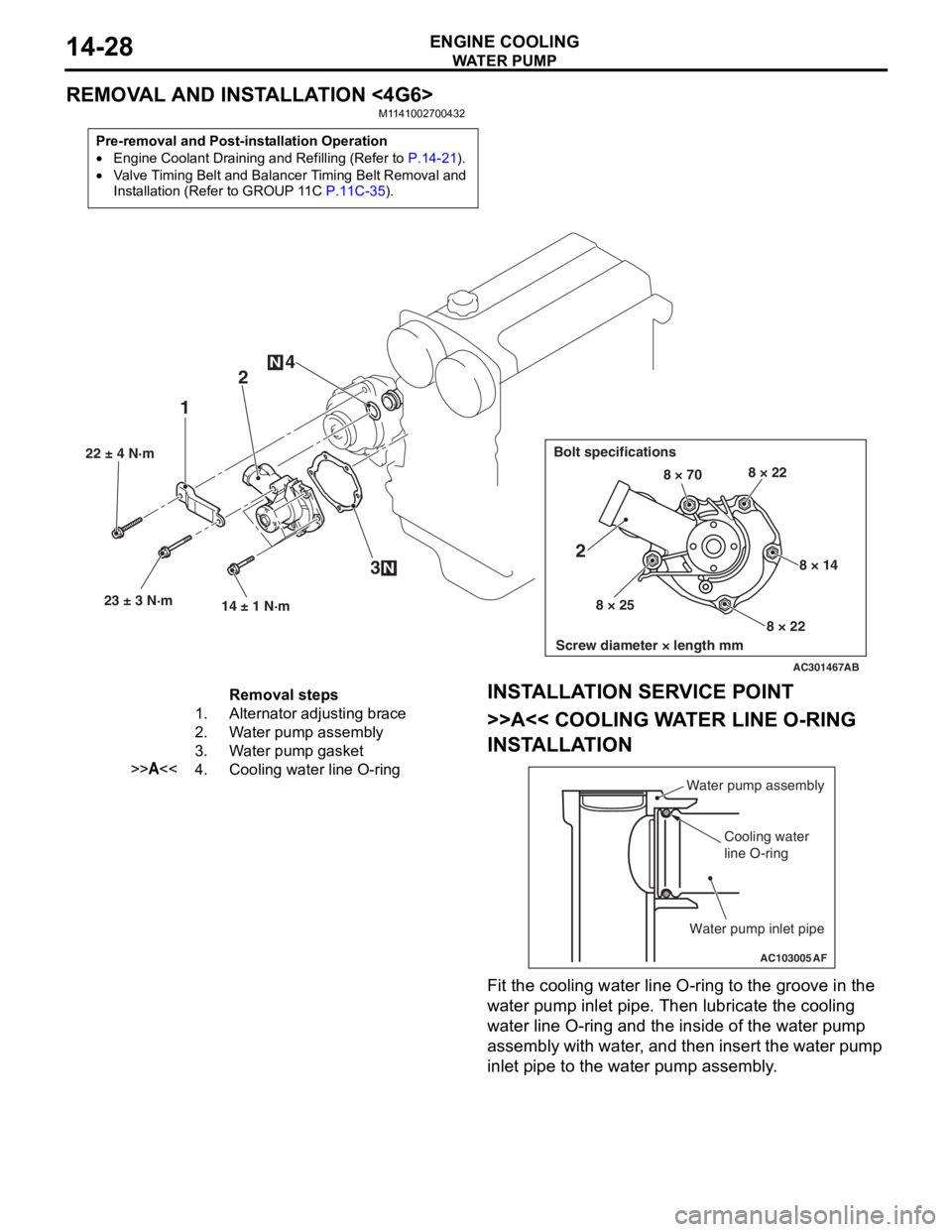
REMOVAL AND INSTALLATION <4G6>
M1141002700432
Pre-removal and Post-installation Operation
•Engine Coolant Draining and Refilling (Refer to P.14-21).
•Valve Timing Belt and Balancer Timing Belt Removal and
Installation (Refer to GROUP 11C
P.11C-35).
AC301467
22 ± 4 N·m23 ± 3 N·m 14 ± 1 N·m
12
3
4
N
N
Bolt specifications
Screw diameter × length mm
8 × 70 8 × 22
8 × 14
8 × 22
8 × 25
2
AB
Removal steps
1.Alternator adjusting brace
2.Water pump assembly
3.Water pump gasket
>>A<<4.Cooling water line O-ring
INST
ALLA T ION SER VICE POINT
>>A<< COOLING WA TER LINE O-RING
INST
ALLA TION
AC103005
Water pump assembly
Cooling water
line O-ring
Water pump inlet pipe
AF
Fit the coo ling water line O-ring to the groove in the
wa
ter pump in let p i pe. T hen lubricate th e co olin g
wa
ter line O-ring and the inside of the wat e r pump
assembly with wa
ter , and then insert the wa ter pu mp
inle
t pip e to the water pu mp asse mbly .
Page 80 of 800
AK202802
CHARGING SYSTEM
ENGINE ELECTRICAL16-18
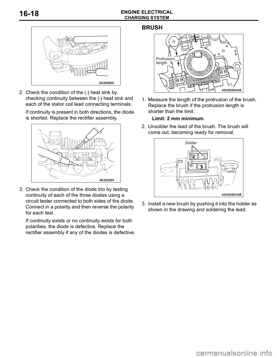
2.Check t he co ndition of the (−) heat sink by
checkin
g
con
t
inuity b
e
tween th e (
−) he at sink and
ea
ch o
f
the st
a
t
or co
il lead conne
cting termina l s.
If con t inu i ty is p r ese n t in bot h d i re ctio ns, the dio de
is shorted.
Re place the rectifier assembly .
AK202804
3.Check t he co ndition of the diode t r io by testing
continuity of ea ch o f the th ree diodes using a
circuit tester con necte d to both sides of the dio de.
Co nnect in a p o la rity a nd then reverse the polarity
fo r each test.
If continuity exist s or no cont inuity exist s for bo th
po
larities, the d i ode is d e fective . Repla c e th e
rectifier assembly if a
n y o f the d i odes is defe c tive.
BRUSH
AK202808
Protrusion
length
AB
1.Measure the lengt h of the prot rusion o f the bru s h.
Replace the b r ush if the protrusion lengt h is
shorter than th e limit .
Limit: 2 mm mini mum
2.Unsolde r the lead o f the br ush. The bru s h will
come out, b e coming ready for removal.
AK202834
Solder
AB
3.I n st all a ne w b r ush b y pu sh in g it int o the h o lde r a s
shown in the d r awing a nd soldering th e lea d .
Page 97 of 800
IGNITION SYSTEM
ENGINE ELECTRICAL16-35
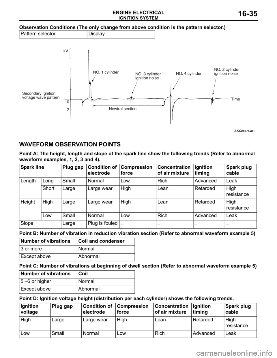
Observation Conditions (The only change from above condition is the pattern selector.)
Pattern selectorDisplay
AKX01275
kV
Secondary ignition
voltage wave pattern 0
2NO. 1 cylinder
NO. 3 cylinder
ignition noise
Newtral section NO. 4 cylinder
NO. 2 cylinder
ignition noise
Time
AC
WA VEFORM OBSER V A T ION POINTS
Point A: The he ight, len g th and s l ope of th e sp a r k line sho w the following trends (Re f er to abnorma l
wave
form exam ples, 1 , 2, 3 a nd 4).
Spark linePlug gapCondition of
electrodeCompression
force Concentration
of air mixtureIgnition
timingSpark plug
cable
LengthLongSmallNormalLowRichAdvancedLeak
ShortLargeLarge wearHigh LeanRetardedHigh
resistance
HeightHighLargeLarge wearHighLeanRetardedHigh
resistance
LowSmallNormalLow RichAdvancedLeak
SlopeLargePlug is fouled−−−−
Point B: Number of v i bra t ion in red uction vi bra t ion sec tion (Refer to a bnormal wavefo r m examp l e 5)
Number of vibrationsCoil and condenser
3 or moreNormal
Except aboveAbnormal
Point C: Number of v i bra t ions a t beginnin g of dwell se ction (Refer to a bnormal wave form exam ple 5)
Number of vibrationsCoil
5 − 6 or higherNormal
Except aboveAbnormal
Point D: Ignition volt a g e height (distribution per each cylinder) s hows the follo wing tren ds.
Ignition
voltagePlug gapCondition of
electrodeCompression
forceConcentration
of air mixtureIgnition
timingSpark plug
cable
HighLargeLarge wearHighLeanRetardedHigh
resistance
LowSmallNormalLowRichAdvancedLeak
Page 134 of 800
GENERAL INFORMATION
FRONT AXLE26-2
GENERAL INFORMATION
M1261000100648
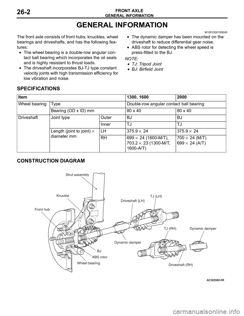
The front axle consists of front hubs, knuckles, wheel
bearings and driveshafts, and has the following fea
-
tures:
•The wheel bearing is a double-row angular con-
tact ball bearing which incorporates the oil seals
and is highly resistant to thrust loads.
•The driveshaft incorporates BJ-TJ type constant
velocity joints with high transmission efficiency for
low vibration and noise.
•The dynamic damper has been mounted on the
driveshaft to reduce differential gear noise.
•ABS rotor for detecting the wheel speed is
press-fitted to the BJ.
NOTE: .
•TJ: Tripod Joint
•BJ: Birfield Joint
SPECIFICATIONS
Item1300, 16002000
Wheel bearingTy p eDouble-row angular contact ball bearing
Bearing (OD x ID) mm80 x 4080 x 40
DriveshaftJoint typeOuterBJBJ
InnerTJTJ
Length (joint to joint) ×
diameter mm LH 375.9 × 24 375.9 × 24
RH699 × 24 (1600-M/T),
703.2
× 23 (1300-M/T,
1600-A/T)
700 × 24 (M/T)
699 × 24 (A/T)
CONSTRUCTION DIAGRAM
AC303569
Front hub KnuckleStrut assembly
TJ (LH)
Driveshaft (LH)
Dynamic damper
BJ
Wheel bearing Driveshaft (RH)
TJ (RH)
AB
ABS rotor
Dynamic damper
Page 135 of 800
SERVICE SPECIFICATIONS
FRONT AXLE26-3
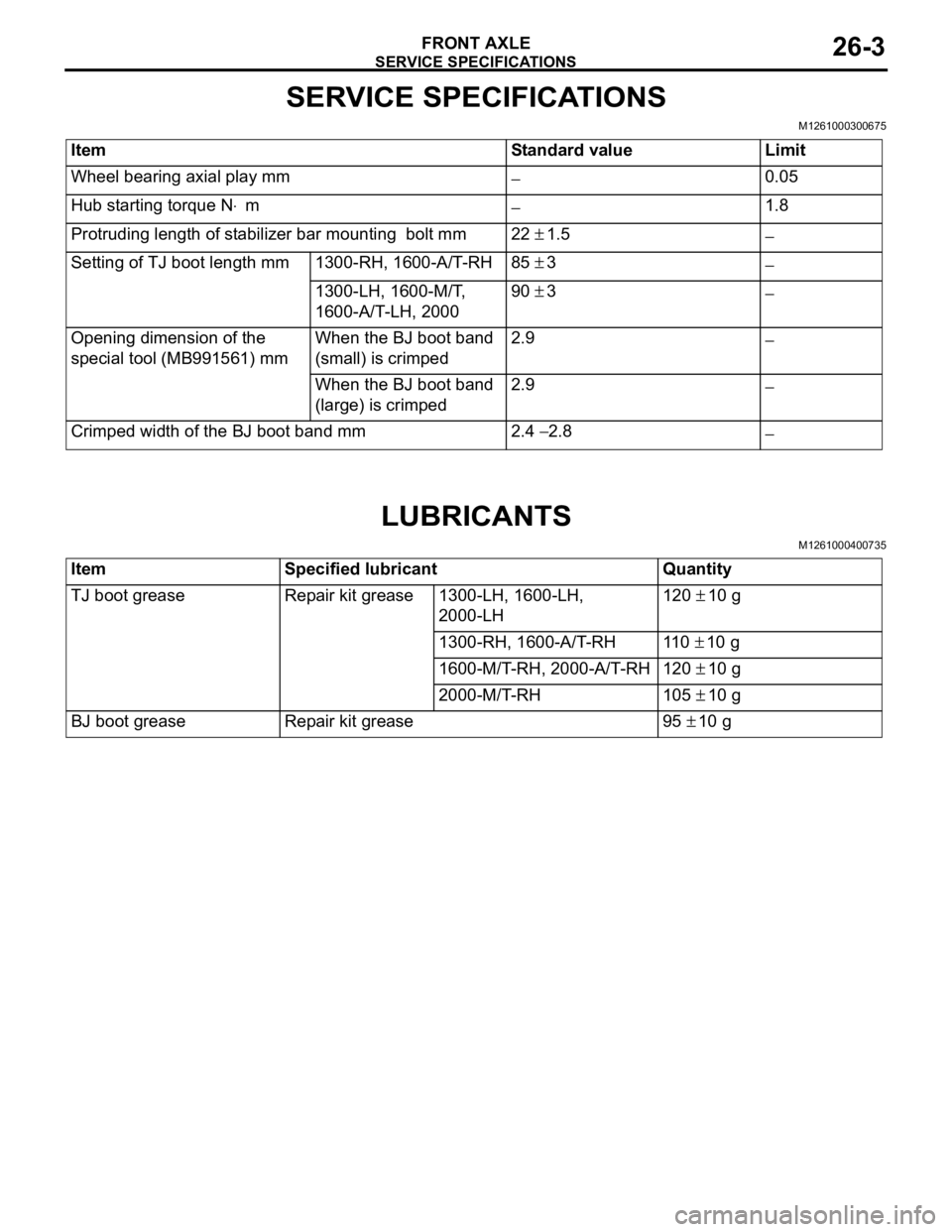
SERVICE SPECIFICATIONS
M1261000300675
ItemStandard valueLimit
Wheel bearing axial play mm−0.05
Hub starting torque N⋅m−1.8
Protruding length of stabilizer bar mounting bolt mm22 ± 1.5−
Setting of TJ boot length mm1300-RH, 1600-A/T-RH85 ± 3−
1300-LH, 1600-M/T,
1600-A/T-LH, 200090 ± 3−
Opening dimension of the
special tool (MB991561) mmWhen the BJ boot band
(small) is crimped2.9−
When the BJ boot band
(large) is crimped2.9 −
Crimped width of the BJ boot band mm2.4 − 2.8−
LUBRICANTS
M1261000400735
ItemSpecified lubricantQuantity
TJ boot greaseRepair kit grease1300-LH, 1600-LH,
2000-LH120 ± 10 g
1300-RH, 1600-A/T-RH11 0 ± 10 g
1600-M/T-RH, 2000-A/T-RH120 ± 10 g
2000-M/T-RH105 ± 10 g
BJ boot greaseRepair kit grease95 ± 10 g
Page 142 of 800
FRONT AXLE HUB ASSEMBLY
FRONT AXLE26-10
<
AC100128
MB990241
MB990767
AG
AC303949
MB990244
(Three)
MB990767
MB990242
MB991354
AF
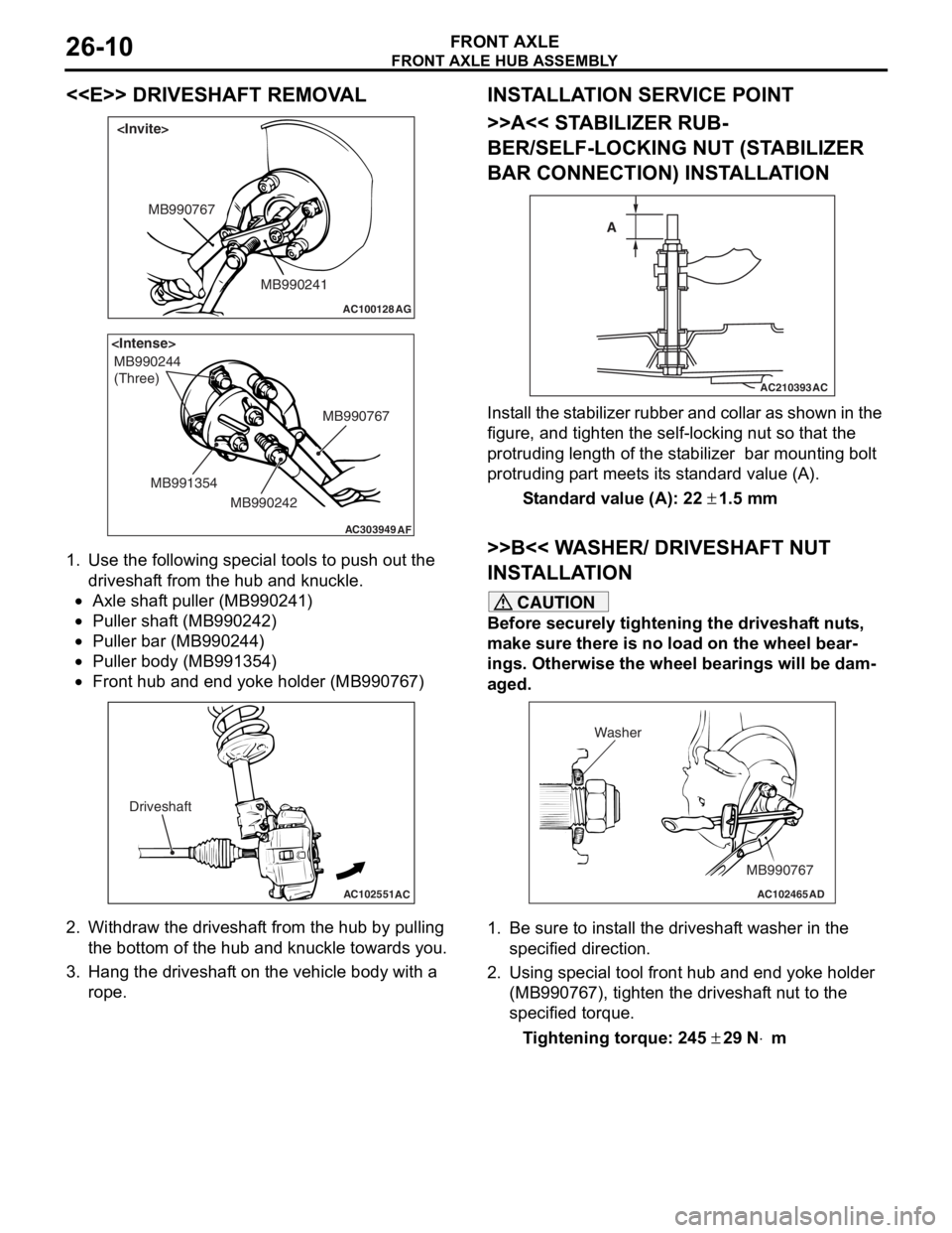
1.
Use the fo llo wing special to ols to pu sh ou t the
driveshaf t from the hub an d kn uckle.
•Axle shaf t puller (MB9 90241 )
•Puller shaft (MB990 242)
•Puller bar (MB990 244)
•Puller body (MB99135 4)
•
AC102551
AC
Driveshaft
Front hub a nd end yoke holder (MB99076 7)
2.Withdraw th e driveshaf t from the hu b by pulling
th e botto m of the hub and knuckle towards you .
3.Hang the dr ive s haf t on the vehicle b ody with a
rope.
INST ALLA T ION SER VICE POINT
>>A<< STABILIZER RUB-
BER/SELF-LOCKING NUT (ST A BILIZER
BAR CONNECTION) INST
ALLA TION
AC210393AC
A
I
n st a ll the st a b ili zer rubb er an d coll ar as sho w n in t he
figure
, and t i ghte n the self-locking nut so tha t the
protruding length
of the st abilize r bar mount ing b o lt
protruding p
a rt meet s it s st and ard value (A).
St andard va lue (A): 22 ± 1.5 m m
>>B<< W A SHER/ DRIVESHAFT NUT
INST
ALLA TION
CAUTION
Before securely tightening the driveshaft nuts,
make sure there is no load on the wheel bear
-
ings. Otherwise the wheel bearings will be dam-
aged.
AC102465AD
MB990767
Washer
1. Be sure to install the driveshaft washer in the
specified direction.
2. Using special tool front hub and end yoke holder (MB990767), tighten the driveshaft nut to the
specified torque.
Tightening torque: 245 ± 29 N⋅m
Page 148 of 800
AC102551AC
Drive shaft
DRIVESHAFT ASSEMBL Y
FRONT AXLE26-16
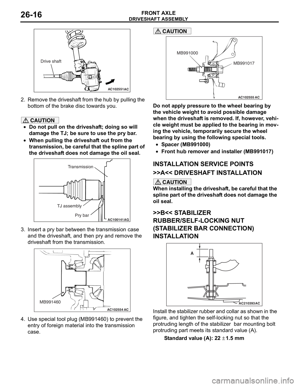
2.Remove th e dr ivesh a f t from th e h ub b y p u lling the
bo ttom of the brake disc toward s you.
CAUTION
•Do not pull on the driveshaft; doing so will
damage the TJ; be sure to use the pry bar.
•
AC100141
Transmission
TJ assembly Pry bar
AG
When pulling the driveshaft out from the
transmission, be careful that the spline part of
the driveshaft does not damage the oil seal.
3. Insert a pry bar between the transmission case and the driveshaft, and then pry and remove the
driveshaft from the transmission.
AC102554
MB991460
AC
4. Use special tool plug (MB991460) to prevent the
entry of foreign material into the transmission
case.
AC102555 AC
MB991017
MB991000
CAUTION
Do not apply pressure to the wheel bearing by
the vehicle weight to avoid possible damage
when the driveshaft is removed. If, however, vehi
-
cle weight must be applied to the bearing in mov-
ing the vehicle, temporarily secure the wheel
bearing by using the following special tools.
•Spacer (MB991000)
•Front hub remover and installer (MB991017)
INSTALLATION SERVICE POINTS
>>A<< DRIVESHAFT INSTALLATION
CAUTION
When installing the driveshaft, be careful that the
spline part of the driveshaft does not damage the
oil seal.
>>B<< STABILIZER
RUBBER/SELF-LOCKING NUT
(STABILIZER BAR CONNECTION)
INSTALLATION
AC210393
AC
A
Install the stabilizer rubber and collar as shown in the
figure, and tighten the self-locking nut so that the
protruding length of the stabilizer bar mounting bolt
protruding part meets its standard value (A).
Standard value (A): 22 ± 1.5 mm
Page 173 of 800
SERVICE SPECIFICATION
POWER PLANT MOUNT32-3
SERVICE SPECIFICATION
M1321000300333
ItemStandard value
Protruding length of stabilizer bar mounting bolt mm22 ± 1.5
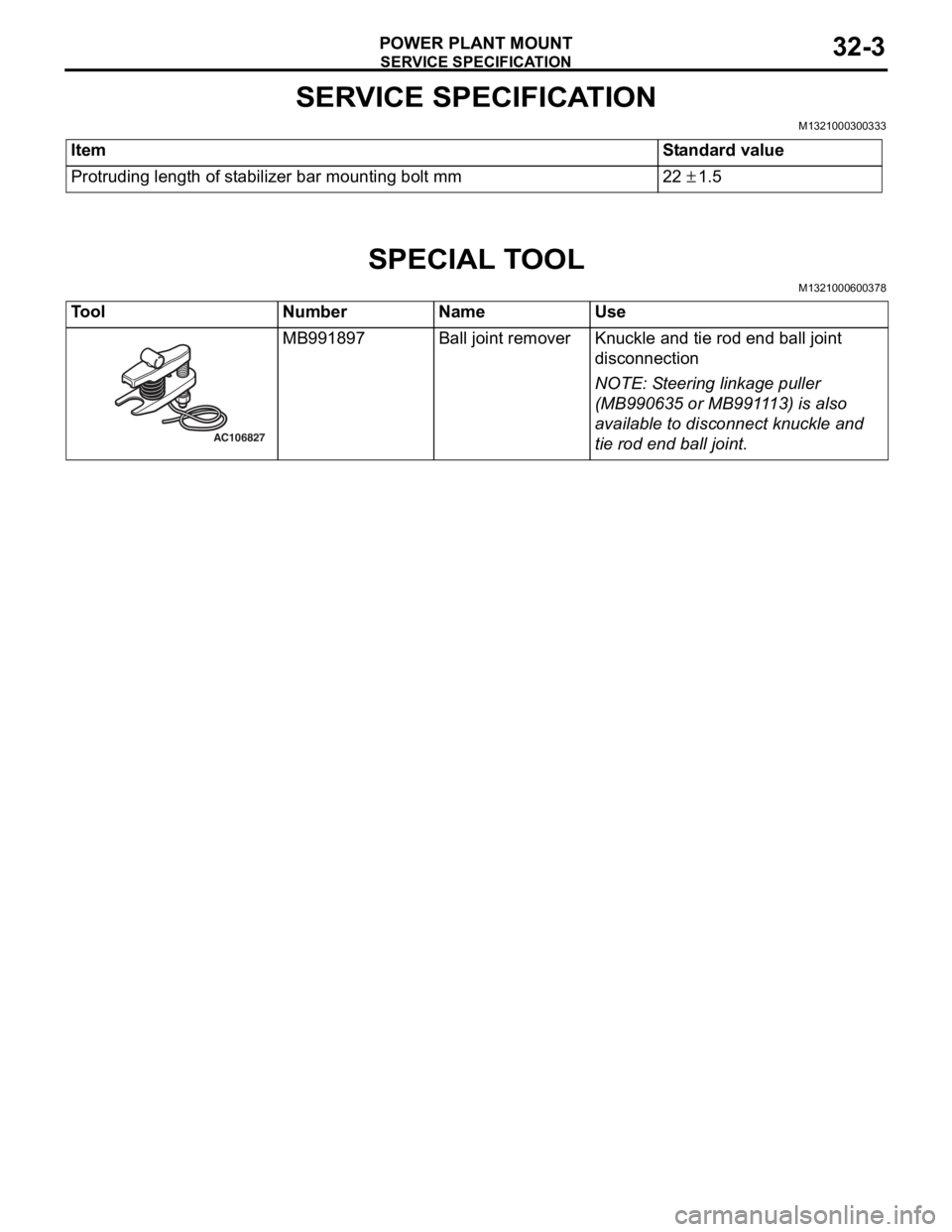
SPECIAL TOOL
M1321000600378
ToolNumberNameUse
AC106827
MB991897Ball j o in t remo verKnuckle and tie rod e nd ball joint
discon
nection
NOTE: St eering linkage pu lle r
(MB990 635 o r MB991 1 13) is also
ava
ilab
l e to disconn ect knuckle and
tie ro
d end ball joint.
Page 181 of 800
