idle speed MITSUBISHI LANCER IX 2006 Service Manual
[x] Cancel search | Manufacturer: MITSUBISHI, Model Year: 2006, Model line: LANCER IX, Model: MITSUBISHI LANCER IX 2006Pages: 800, PDF Size: 45.03 MB
Page 66 of 800

CHARGING SYSTEM
ENGINE ELECTRICAL16-4
2. Turn the ignition switch to the "LOCK" (OFF)
position.
3. Disconnect the negative battery cable.
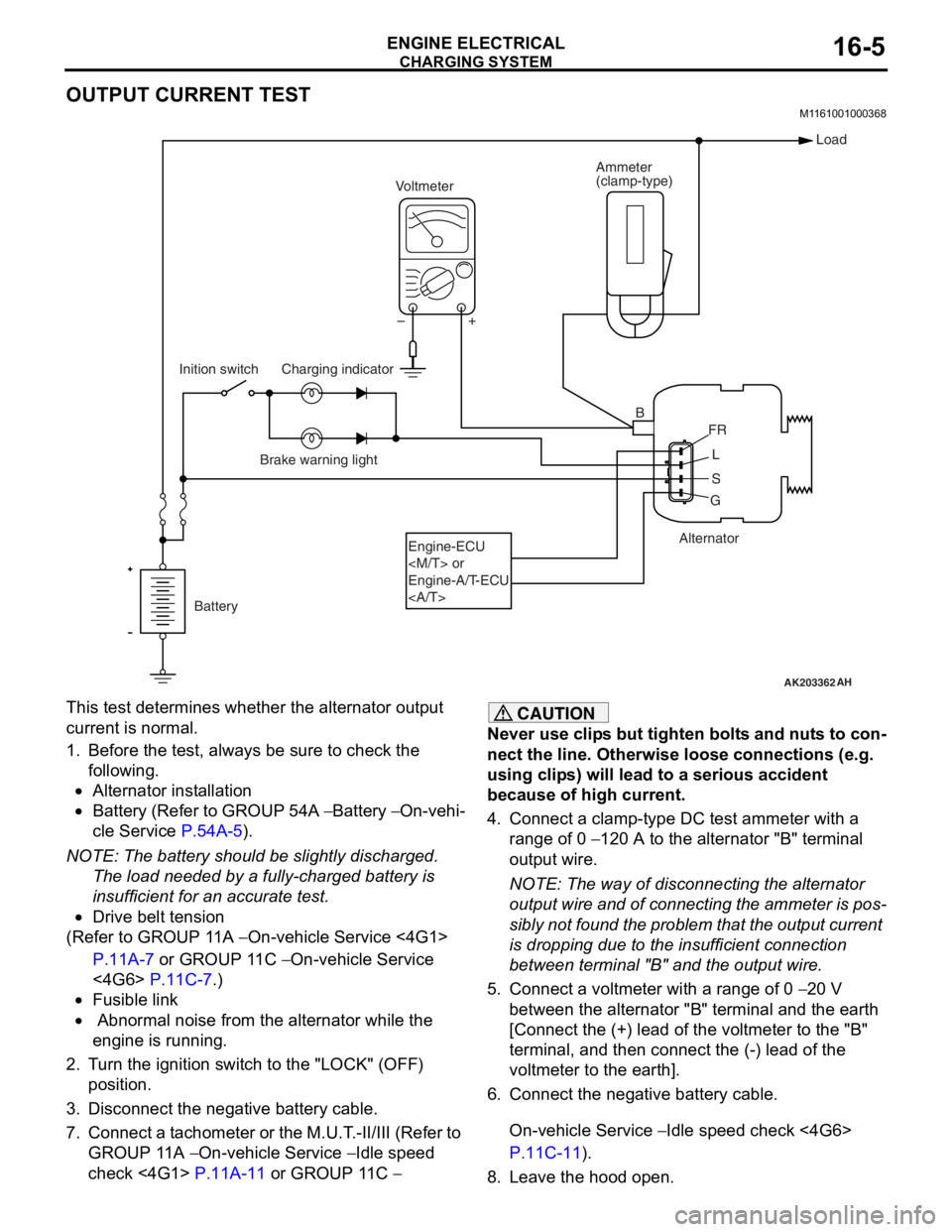
4. Connect a clamp-type DC test ammeter with a
range of 0
− 120 A to the alternator "B" terminal
output wire.
NOTE: The way of disconnecting the alternator
output wire and of connecting the ammeter is pos
-
sibly not found the problem that the output current
is dropping due to the insufficient connection
between terminal "B" and the output wire.
5. Connect a digital-type voltmeter between the
alternator "B" terminal and the battery (+)
terminal. [Connect the (+) lead of the voltmeter to
the "B" terminal and the connect the (-) lead of the
voltmeter to the battery (+) cable].
6. Reconnect the negative battery cable.
7. Connect a tachometer or the M.U.T.-II/III (Refer to
GROUP 11A
− On-vehicle Service − Idle speed
check <4G1>
P.11A-11 or GROUP 11C −
On-vehicle Service − Idle speed check <4G6>
P.11C-11).
8. Leave the hood open.
9. Start the engine.
10.With the engine running at 2,500 r/min, turn the
headlamps and other lamps on and off to adjust
the alternator load so that the value displayed on
the ammeter is slightly above 30 A.
Adjust the engine speed by gradually decreasing
it until the value displayed on the ammeter is 30
A. Take a reading of the value displayed on the
voltmeter at this time.
Limit: maximum 0.3 V
NOTE: When the alternator output is high and the
value displayed on the ammeter does not
decrease until 30 A, set the value to 40 A. Read
the value displayed on the voltmeter at this time.
When the value range is 40 A, the limit is maxi
-
mum 0.4 V.
11.If the value displayed on the voltmeter is above
the limit value, there is probably a malfunction in
the alternator output wire, so check the wiring
between the alternator "B" terminal and the
battery (+) terminal (including fusible link).
If a terminal is not sufficiently tight or if the
harness has become discolored due to
overheating, repair and then test again.
12.After the test, run the engine at idle.
13.Turn off all lamps and the ignition switch.
14.Remove the tachometer or the M.U.T.-II/III.
15.Disconnect the negative battery cable.
16.Disconnect the ammeter and voltmeter.
17.Connect the negative battery cable.
Page 67 of 800
Page 68 of 800

CHARGING SYSTEM
ENGINE ELECTRICAL16-6
9. Check that the reading on the voltmeter is equal
to the battery voltage.
NOTE: If the voltage is 0 V, the cause is probably
an open circuit in the wire or fusible link between
the alternator "B" terminal and the battery (+) ter
-
minal.
10.Turn the light switch on to turn on headlamps and
then start the engine.
11.Immediately after setting the headlamps to high
beam and turning the heater blower switch to the
high revolution position, increase the engine
speed to 2,500 r/min and read the maximum
current output value displayed on the ammeter.
Limit: 70 % of normal current output
NOTE: .
•For the nominal current output, refer to the
Alternator Specifications.
•Because the current from the battery will soon
drop after the engine is started, the above step
should be carried out as quickly as possible in
order to obtain the maximum current output
value.
•The current output value will depend on the
electrical load and the temperature of the
alternator body.
•If the electrical load is small while testing, the
specified level of current may not be output
even though the alternator is normal. In such
cases, increase the electrical load by leaving
the headlamps turned on for some time to dis
-
charge the battery or by using the lighting sys-
tem in another vehicle, and then test again.
•The specified level of current also may not be
output if the temperature of the alternator body
or the ambient temperature is too high. In such
cases, cool the alternator and then test again.
12.The reading on the ammeter should be above the
limit value. If the reading is below the limit value
and the alternator output wire is normal, remove
the alternator from the engine and check the
alternator.
13.Run the engine at idle after the test.
14.Turn the ignition switch to the "LOCK" (OFF)
position.
15.Remove the tachometer or the M.U.T.-II/III.
16.Disconnect the negative battery cable.
17.Disconnect the ammeter and voltmeter.
18.Connect the negative battery cable.
Page 69 of 800
Page 70 of 800

CHARGING SYSTEM
ENGINE ELECTRICAL16-8
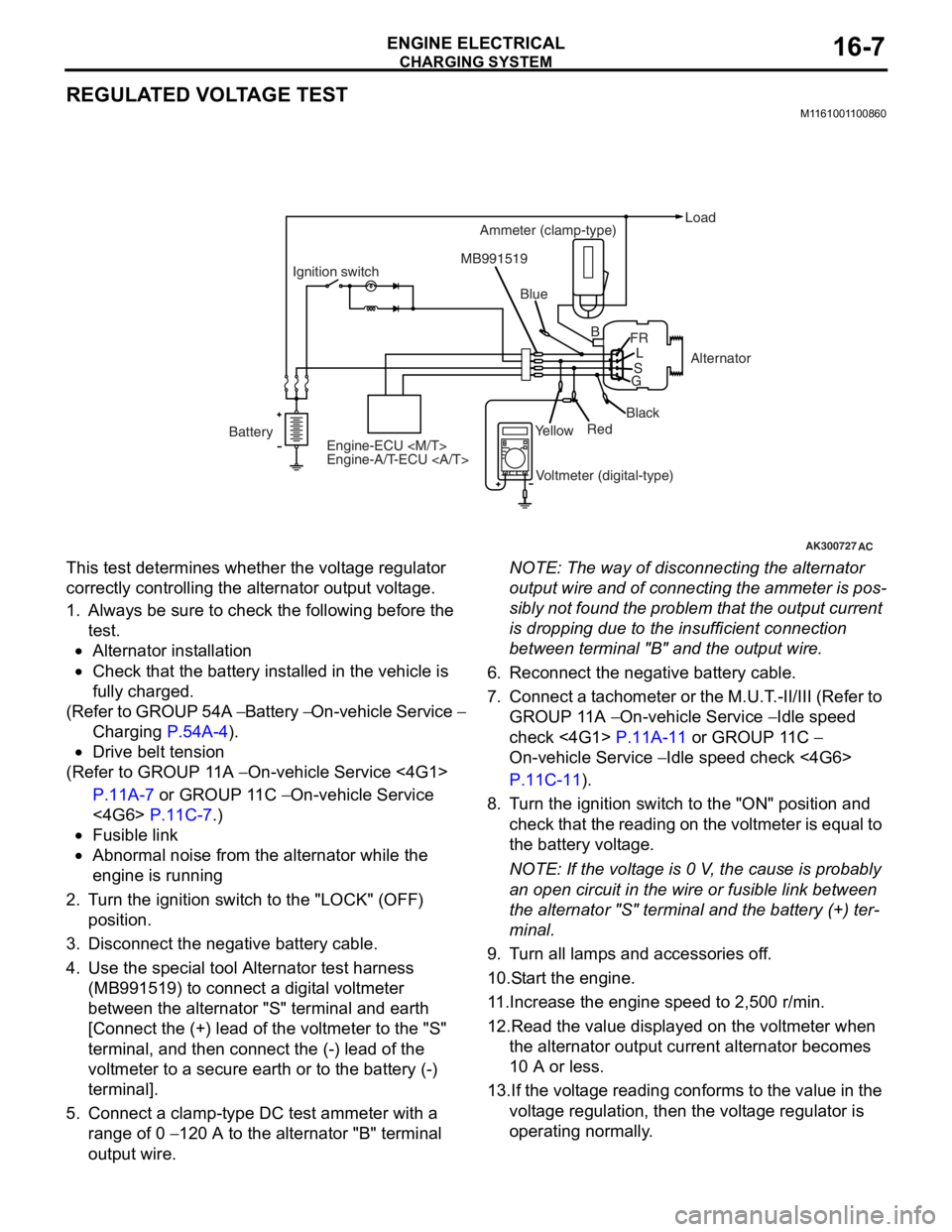
If the voltage is not within the standard value,
there is a malfunction of the voltage regulator or of
the alternator.
14.After the test, lower the engine speed to the idle speed.
15.Turn the ignition switch to the "LOCK" (OFF) position.
16.Remove the tachometer or the M.U.T.-II/III.
17.Disconnect the negative battery cable.
18.Disconnect the ammeter and voltmeter.
19.Connect the alternator output wire to the alternator "B" terminal.
20.Remove the special tool, and return the connector
to the original condition.
21.Connect the negative battery cable.
Voltage Regulation Table
Standard value:
Inspection terminalVoltage regulator ambient
temperature
°C
Voltage V
Terminal "S"−2014.2 − 15.4
2013.9 − 14.9
6013.4 − 14.6
8013.1 − 14.5
Page 71 of 800
CHARGING SYSTEM
ENGINE ELECTRICAL16-9
WAVEFORM CHECK USING AN OSCILLOSCOPE
M1161001200124
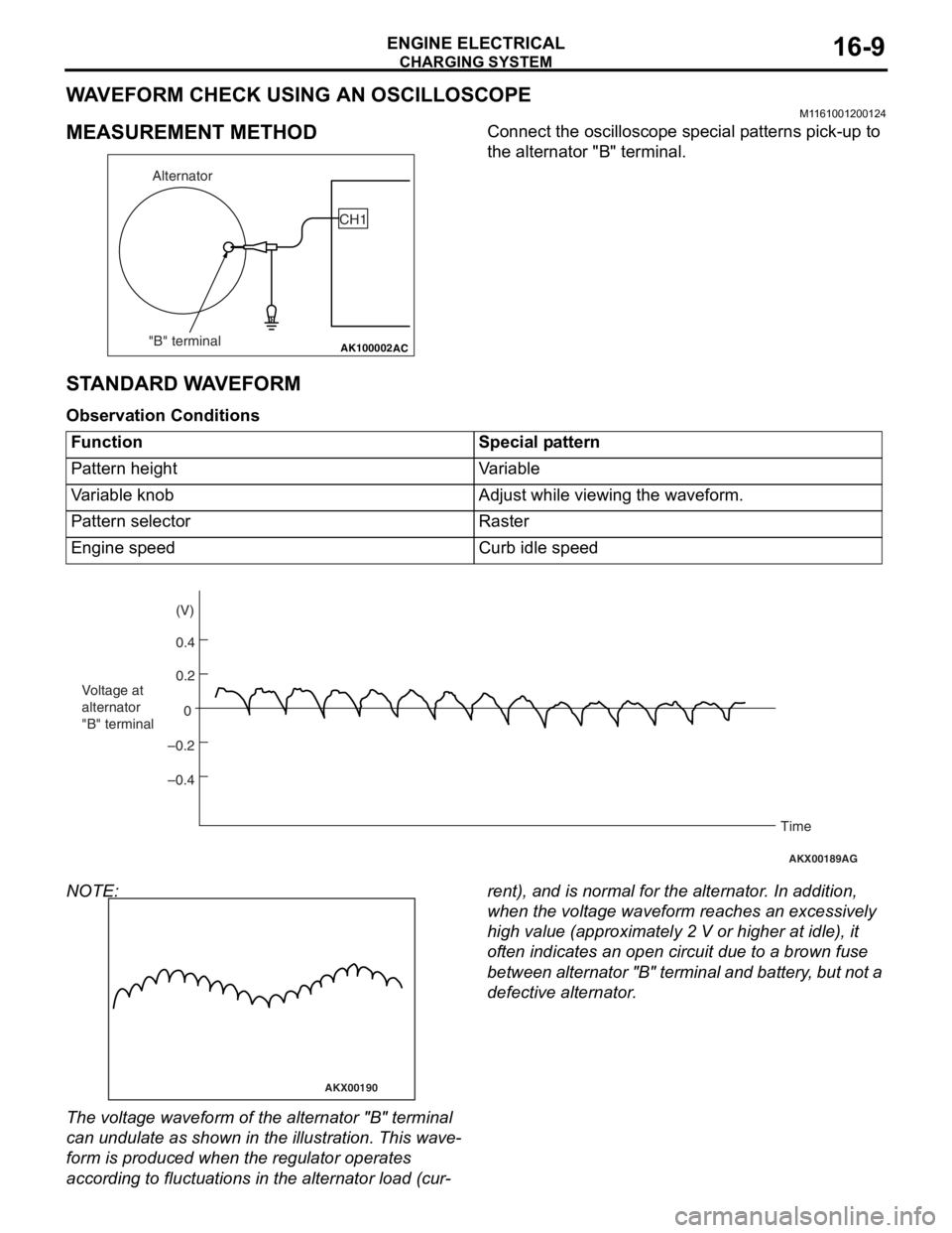
MEASUREMENT METHOD
AK100002
Alternator
"B" terminal CH1
AC
Co
nnect the oscillo scope specia l p a tt erns p i ck-up to
the alternato
r "B" terminal.
STANDARD W A VEFORM
Observ ation Conditi ons
FunctionSpecial pattern
Pattern heightVariable
Variable knobAdjust while viewing the waveform.
Pattern selectorRaster
Engine speedCurb idle speed
AKX00189
0.4 (V)
0.2
0
–0.2
–0.4
Voltage at
alternator
"B" terminal
Time
AG
NOTE:
AKX00190
The volt age waveform of th e alte rnator "B" t e rminal
can u
ndulate as sho w n in th e illustratio n . This wave
-
form is produce d when t he regu lator operate s
accordin
g to fluctu ation s in the alterna t or loa d (cu r
-
rent), and is normal fo r the alterna t or . In ad dition,
wh
en the volt ag e wavef o rm re ache s an excessively
high
value (app roximate ly 2 V or higher at idle ), it
of
ten indicates an o pen circuit du e to a brown fuse
be
twe e n a l te rn at or "B " t e r m in al an d ba tt er y , b u t n o t a
defective alte
rnator .
Page 96 of 800
IGNITION SYSTEM
ENGINE ELECTRICAL16-34
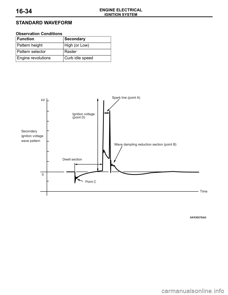
STANDARD WAVEFORM
Observation Conditions
FunctionSecondary
Pattern heightHigh (or Low)
Pattern selectorRaster
Engine revolutionsCurb idle speed
AKX00278
kV0
Secondary
ignition voltage
wave pattern
Ignition voltage
(point D)
Spark line (point A)
Dwell section Wave dampling reduction section (point B)
Point C Time
AD
Page 108 of 800
ENGINE CONTROL
ENGINE AND EMISSION CONTROL17-2
ENGINE CONTROL
GENERAL INFORMATIONM1171000100277
A cable-type accelerator mechanical sus-
pended-type pedal has been adopted.
SERVICE SPECIFICATIONS
M1171000300088
ItemStandard value
Accel cable play mm1.0 − 2.0
Engine idle speed r/min4G1750 ± 50
4G6750 ± 100
ON-VEHICLE SERVICE
ACCEL CABLE CHECK AND
ADJUSTMENT
M1171000900314
1. Turn A/C and lights OFF. Inspect and adjust at no load.
2. Warm engine until stabilized at idle.
3. Confirm idle speed is at standard value.
Standard value:
750 ± 50 r/min <4G1>
750 ± 100 r/min <4G6>
4. Stop engine. [ignition switch: LOCK (OFF)
position].
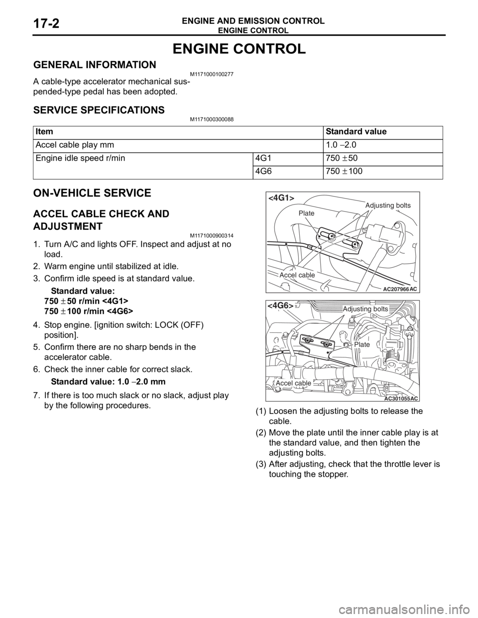
5. Confirm there are no sharp bends in the accelerator cable.
6. Check the inner cable for correct slack.
Standard value: 1.0 − 2.0 mm
7. If there is too much slack or no slack, adjust play by the following procedures.
AC207966
Adjusting bolts
Plate
Accel cable
AC
<4G1>
AC301055
Adjusting bolts
Plate
Accel cable
AC
<4G6>
(1) Loosen th e adjusting bo lt s to re lease the
cab l e.
(2) M o v e th e pla t e until the inne r cab l e play is a t
the st andard value, an d then tighte n the
adjusting bo lt s.
(3) A f t e r adju s ting, check that the thro ttle leve r is
touching the stoppe r .
Page 117 of 800
EMISSION CONTROL
ENGINE AND EMISSION CONTROL17-11
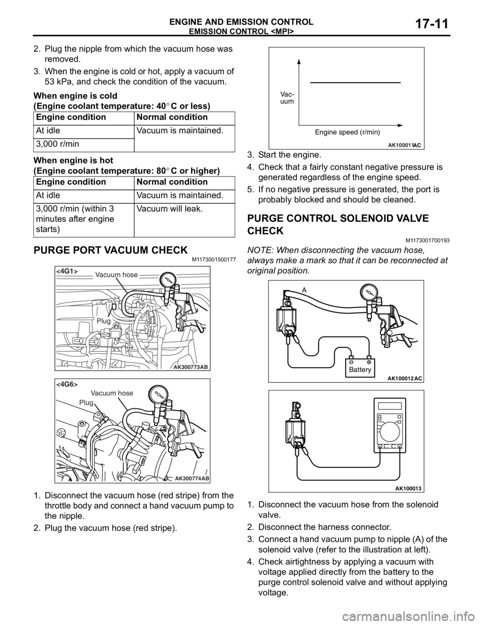
2. Plug the nipple from which the vacuum hose was removed.
3. When the engine is cold or hot, apply a vacuum of 53 kPa, and check the condition of the vacuum.
When engine is cold
(Engine coolant temperature: 40°C or less)
Engine conditionNormal condition
At idleVacuum is maintained.
3,000 r/min
When engine is hot
(Engine coolant temperature: 80°C or higher)
Engine conditionNormal condition
At idleVacuum is maintained.
3,000 r/min (within 3
minutes after engine
starts)Vacuum will leak.
PURGE PORT VACUUM CHECKM1173001500177
AK300773
<4G1>
AB
Plug
Vacuum hose
AK300774
<4G6>
AB
Plug
Vacuum hose
1.Disco nnect th e vacuum ho se (red st ripe) from the
throttle body and connect a hand vacuum pump to
th e nip p le.
2.Plu g the vacuum hose (red stripe).
AK100011AC
Vac-
uum
Engine speed (r/min)
3.S t art the engine.
4.Check t hat a f a irly co nst ant n egative p r essure is
g enerate d regard l ess of the en gine spee d.
5.If no neg ative pressur e is genera t ed, th e port is
p r obably blocked an d sh ould be cleane d.
PURGE CONTROL SOLENOID VA L V E
CHECK
M1173 0017 0019 3
NOTE: Whe n discon nect i ng th e va cuum hose,
always make a mark so th at it can be reconnected at
original p o sition.
AK100012AC
Battery
A
AK100013
1.
Disco nnect the vacu um h o se f r om th e solenoid
valve.
2.Disco nnect the ha rness connector .
3.Con nect a ha nd vacu um pump to nipp le (A) of the
solen o id valve (ref e r to th e ill ust r ation at le f t ).
4.Check a i rtig htness b y app lying a vacuum with
volt age applied d i rectly from t he batt e ry to the
p u rge con t rol so leno id valve an d without app lying
volt age .
Page 242 of 800
ON-VEHICLE SERVICE
POWER STEERING37-12
TIE ROD END BALL JOINT TURNING
TORQUE CHECK
M1372001500554
CAUTION
•Do not remove the tie rod end nut from the
ball joint. Loosen it and use special tool to
avoid possible damage to the ball joint
threads.
•
AC208247AJ
CordBoltMB991897
or
MB992011
Nut
Ball joint
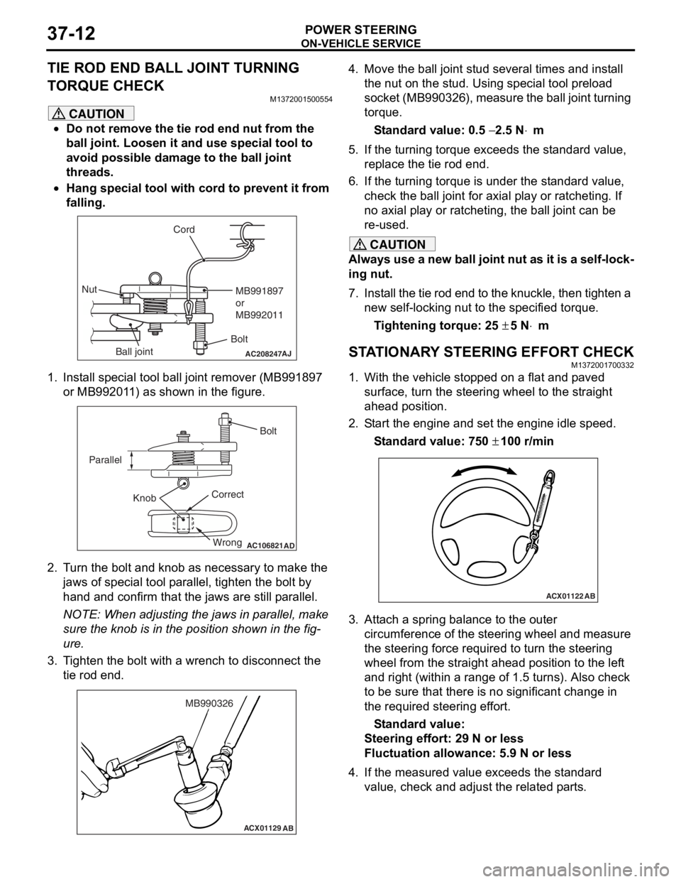
Hang special tool with cord to prevent it from
falling.
1. Install special tool ball joint remover (MB991897 or MB992011) as shown in the figure.
AC106821
Knob
Parallel
Bolt
Correct Wrong
AD
2. Turn the bolt and knob as necessary to make the jaws of special tool parallel, tighten the bolt by
hand and confirm that the jaws are still parallel.
NOTE: When adjusting the jaws in parallel, make
sure the knob is in the position shown in the fig
-
ure.
3. Tighten the bolt with a wrench to disconnect the tie rod end.
ACX01129 AB
MB990326
4. Move the ball joint stud several times and install
the nut on the stud. Using special tool preload
socket (MB990326), measure the ball joint turning
torque.
Standard value: 0.5 − 2.5 N⋅m
5. If the turning torque exceeds the standard value, replace the tie rod end.
6. If the turning torque is under the standard value, check the ball joint for axial play or ratcheting. If
no axial play or ratcheting, the ball joint can be
re-used.
CAUTION
Always use a new ball joint nut as it is a self-lock-
ing nut.
7. Install the tie rod end to the knuckle, then tighten a new self-locking nut to the specified torque.
Tightening torque: 25 ± 5 N⋅m
STATIONARY STEERING EFFORT CHECKM1372001700332
1. With the vehicle stopped on a flat and paved
surface, turn the steering wheel to the straight
ahead position.
2. Start the engine and set the engine idle speed.
Standard value: 750 ± 100 r/min
ACX01122 AB
3. Attach a spring balance to the outer
circumference of the steering wheel and measure
the steering force required to turn the steering
wheel from the straight ahead position to the left
and right (within a range of 1.5 turns). Also check
to be sure that there is no significant change in
the required steering effort.
Standard value:
Steering effort: 29 N or less
Fluctuation allowance: 5.9 N or less
4. If the measured value exceeds the standard value, check and adjust the related parts.