set clock MITSUBISHI LANCER IX 2006 Service Manual
[x] Cancel search | Manufacturer: MITSUBISHI, Model Year: 2006, Model line: LANCER IX, Model: MITSUBISHI LANCER IX 2006Pages: 800, PDF Size: 45.03 MB
Page 90 of 800

AK202711
SegmentUndercut
Mica
AB
ST ARTING SYS TEM
ENGINE ELECTRICAL16-28
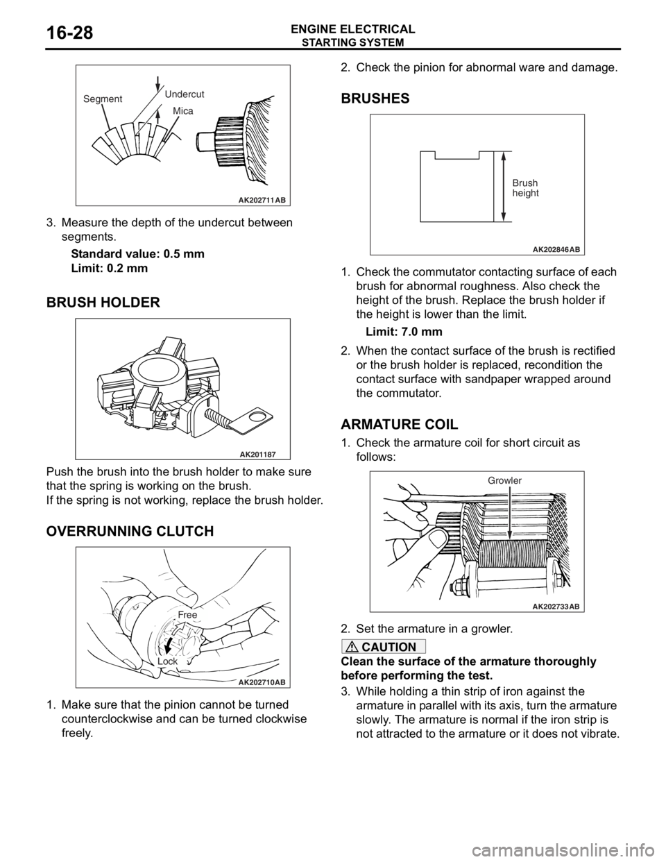
3.Measure the depth of the undercut be twe en
segment s.
St andard va lue: 0.5 mm
Limit: 0.2 mm
BRUSH HOLDER
AK201187
Push th e brush in to the b r ush hold e r to make sure
that the
spring is working o n the b r ush.
If the spring is not working, repla c e th e brush holder .
OVERRUNNING CLUTCH
AK202710
Free
Lock
AB
1.Make sure that th e pin i on canno t be tu rned
counte r clo ckwise a nd ca n be tu rned clockwise
fre e ly .
2.Check t he pinion for abn ormal ware an d damage.
BRUSHES
AK202846
Brush
height
AB
1.Che ck the commut ator con t a c tin g surface of each
b r ush f o r abno rmal rough ness. Also ch eck the
h e ight of the brush . Replace th e brush holder if
th e height is lo we r than t he limit.
Limit: 7.0 mm
2.Wh en the con t act su rface of the brush is rectified
o r the bru s h h o lder is re placed, re cond itio n the
cont act surfa c e wit h san d p a p e r wrapped around
th e co mmu t a t o r .
ARMATURE COIL
1.Check t he armature coil for short circuit a s
fo llows:
AK202733
Growler
AB
2.Set the armature in a growler .
CAUTION
Clean the surface of the armature thoroughly
before performing the test.
3. While holding a thin strip of iron against the
armature in parallel with it s axis, turn the armature
slowly. The armature is normal if the iron strip is
not attracted to the armature or it does not vibrate.
Page 178 of 800

CROSSMEMBER
POWER PLANT MOUNT32-8
INSTALLATION SERVICE POINTS
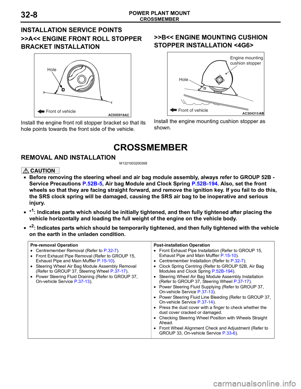
>>A<< ENGINE FRONT ROLL STOPPER
BRACKET INSTALLATION
AC005918Front of vehicleHoleAC
Inst
all th e en gine fron t roll stop per b r acket so that it s
hole
point s towards the fro n t side of the vehicle.
>>B<< ENGINE MOUNTING CUSHION
ST
OPPER INST ALLA TION <4G6>
AC304315ABFront of vehicle
Hole Engine mounting
cushion stopper
Inst
all the e ngin e mo untin g cushio n sto pper a s
shown.
CROSSMEMBER
REMOVA L AND INST ALLA TIONM13210032 0036 8
CAUTION
•Before removing the steering wheel and air bag module assembly, always refer to GROUP 52B -
Service Precautions
P.52B-5, Air bag Module and Clock Spring P.52B-194. Also, set the front
wheels so that they are facing straight forward, and remove the ignition key. If you fail to do this,
the SRS clock spring will be damaged, causing the SRS air bag to be inoperative and serious
injury.
•*1: Indicates parts which should be initially tightened, and then fully tightened after placing the
vehicle horizontally and loading the full weight of the engine on the vehicle body.
•
Pre-removal Operation
•Centremember Removal (Refer to P.32-7).
•Front Exhaust Pipe Remova l (Refer to GROUP 15,
Exhaust Pipe and Main Muffler P.15-10).
•Steering Wheel Air Bag Mo dule Assembly Removal
(Refer to GROUP 37, Steering Wheel P.37-17).
•Power Steering Fluid Draining (Refer to GROUP 37,
On-vehicle Service P.37-13).
Post-installation Operation
•Front Exhaust Pipe Installation (Refer to GROUP 15,
Exhaust Pipe and Main Muffler
P.15-10).
•Centremember Installation (Refer to P.32-7).
•Clock Spring Centring (Refer to GROUP 52B, Air Bag
Modules and Clock Spring P.52B-194).
•Steering Wheel Air Bag Module Assembly Installation
(Refer to GROUP 37, Steering Wheel P.37-17).
•Power Steering Fluid Supplying (Refer to GROUP 37,
On-vehicle Service P.37-13).
•Power Steering Fluid Line Bleeding (Refer to GROUP 37,
On-vehicle Service P.37-14).
•Press the dust cover with a finger to check whether the
dust cover cracked or damaged.
•Checking Steering Wheel Position with Wheels Straight
Ahead.
•Front Wheel Alignment Check and Adjustment (Refer to
GROUP 33, On-vehicle Service P.33-6).
*2: Indicates parts which should be temporarily tightened, and then fully tightened with the vehicle
on the earth in the unladen condition.
Page 263 of 800

POWER STEERING GEAR BOX AND LINKAGE
POWER STEERING37-33
Specified sealant: 3M ATD Part No.8661 or
equivalent
2. Secure the threaded portion of the end plug at two places by using a punch.
>>J<< RACK SUPPORT COVER/LOCK
NUT INSTALLATION
1. Position the rack at its centre.
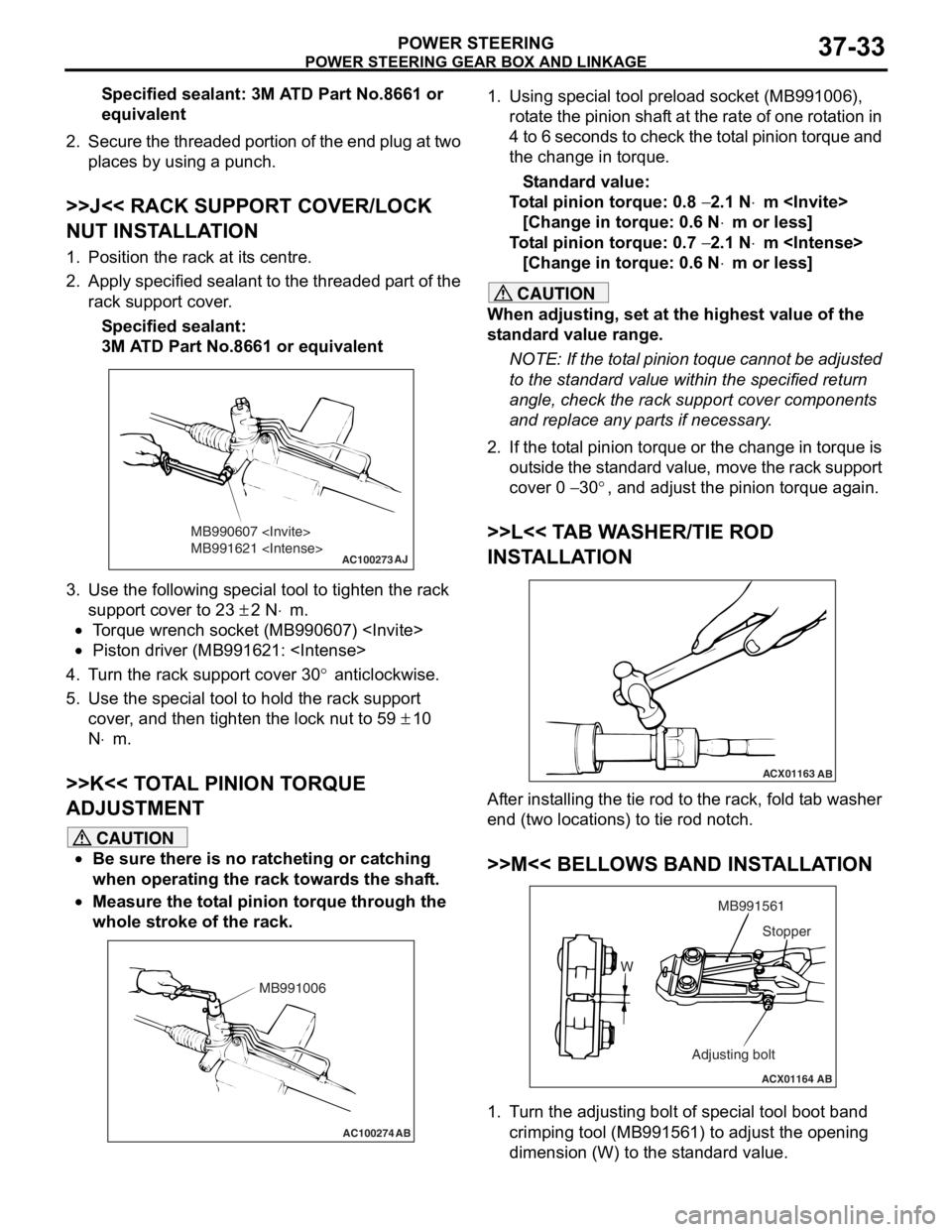
2. Apply specified sealant to the threaded part of the
rack support cover.
Specified sealant:
3M ATD Part No.8661 or equivalent
AC100273
MB990607
MB991621
AJ
3.Use the fo llo wing special to ol to tigh ten the rack
suppor t cover to 2 3
± 2 N⋅m.
•To rque wren ch socket (MB990607 )
•Piston driver (MB9916 21:
4.T u rn the rack suppo rt cover 30° anticlockwise .
5.Use the special tool to hold the r a ck sup port
cove r , and t hen tighten the lock nut to 59
± 10
N
⋅m.
>>K<< T O T A L PINION T O RQUE
ADJUSTMENT
CAUTION
•Be sure there is no ratcheting or catching
when operating the rack towards the shaft.
•
AC100274 AB
MB991006
Measure the total pinion torque through the
whole stroke of the rack.
1. Using special tool preload socket (MB991006),
rotate the pinion shaft at the rate of one rotation in
4 to 6 seconds to check the total pinion torque and
the change in torque.
Standard value:
Total pinion torque: 0.8 − 2.1 N⋅m
[Change in torque: 0.6 N
⋅m or less]
Total pinion torque: 0.7 − 2.1 N⋅m
[Change in torque: 0.6 N
⋅m or less]
CAUTION
When adjusting, set at the highest value of the
standard value range.
NOTE: If the total pinion toque cannot be adjusted
to the standard value within the specified return
angle, check the rack support cover components
and replace any parts if necessary.
2. If the total pinion torque or the change in torque is outside the standard value, move the rack support
cover 0
− 30°, and adjust the pinion torque again.
>>L<< TAB WASHER/TIE ROD
INSTALLATION
ACX01163 AB
After installing the tie rod to the rack, fold tab washer
end (two locations) to tie rod notch.
>>M<< BELLOWS BAND INSTALLATION
ACX01164 AB
W MB991561
Adjusting bolt Stopper
1. Turn the adjusting bolt of special tool boot band
crimping tool (MB991561) to adjust the opening
dimension (W) to the standard value.