heater MITSUBISHI MIRAGE G4 2018 (in English) User Guide
[x] Cancel search | Manufacturer: MITSUBISHI, Model Year: 2018, Model line: MIRAGE G4, Model: MITSUBISHI MIRAGE G4 2018Pages: 263, PDF Size: 37.9 MB
Page 179 of 263

Manual air conditioning (if so equipped) 7-8 Comfort controls
7
N00736601258
Turn the temperature control dial clockwise to make the air warmer
. Turn it counterclock-
wise to make the air cooler.
N00736701246
To change air flow di
rection, turn the mode
selection dial. Refer to “Changing the mode selection” on page 7-2.
N00736801423
Normally, use the outside air position to keep the windshield and side windows clear and to quickly remove fog or frost from the wind-shield. To change the air selection, use the air selec- tion lever. “ ” Outside air “ ” Recirculated air
If the outside air is dusty or contaminated in some way, use the
recirculat
ion position.
Switch to the outside
air position every now
and then to keep the windows from foggingup.
Temperature control dial
NOTE
While the engine coolant temperature is low, the temperature of the air from the heater will be cool/cold until
the engine warms up,
even if you have selected warm air with the dial.
Mode selection dial
Air selection lever
BK0249600US.book 8 ページ 2017年4月20日 木曜日 午後1時36分
Page 185 of 263

Automatic air conditioning (if so equipped) 7-14 Comfort controls
7
The above indicates the
factory settings. You
can personalize the air
selection switch and
air conditioning switch to match your per-sonal preferences. Contact your Mitsubishi
Motors dealer or a
repair facility of your choice for assistance.Refer to “Personalizi
ng the air conditioning
switch (Changing the function setting)” on
page7-16. Refer to “Personalizing the air selection(Changing the function setting)” on page7-15.
N00737101247
To change air flow direction, press theMODE switch. Each time the MODE switch is pressed, the mode ch
anges to the next one
in the following sequence: “ ”
“”
“”
“”
“ ”. The selected mode
is shown in the displa
y (A). Refer to “Chang-
ing the mode selection” on page 7-2.
N00703400015
When this switch is pressed, the mode changes to the “ ” mode. The indicator
light (A) will come on. The selected mode is shown in the display (B). Refer to “Changingthe mode selection” on page 7-2.
N00737200368
Normally, use the outside air position to keepthe windshield and side windows clear and to quickly remove fog or frost from the wind- shield.
While the engine coolant temperature is low, the temperature of the air from the heaterwill be cool/cold until
the engine warms up,
even if you have selected warm air with the switch. To prevent the windshield and windows fromfogging up, the vent mode
will be changed to
“ ” and the blower sp
eed will be reduced.
When the temperature is set to the highest or the lowest setting under the AUTO opera- tion, the air selection
and the air conditioning
will be automatically changed as follows. • Quick Heating (When th
e temperature is set
to the highest setting) Outside air will be introduced and the air conditioning will stop.If the air selection
and the air conditioning
are operated ma
nually after an automatic
changeover, manual
operation will be
selected. • Quick Cooling (When th
e temperature is set
to the lowest setting) Inside air will be recirculated and the air conditioning wi
ll operate.
NOTE
MODE switch
Defogger switch
NOTE
When the defogger switch is pressed, the air conditioning system au
tomatically operates
and outside air (as oppos
ed to recirculated
air) is selected.Refer to “Defrosting or defogging (wind- shield, door windows)” on page 7-17.
Air selection switch
BK0249600US.book 14 ページ 2017年4月20日 木曜日 午後1時36分
Page 233 of 263
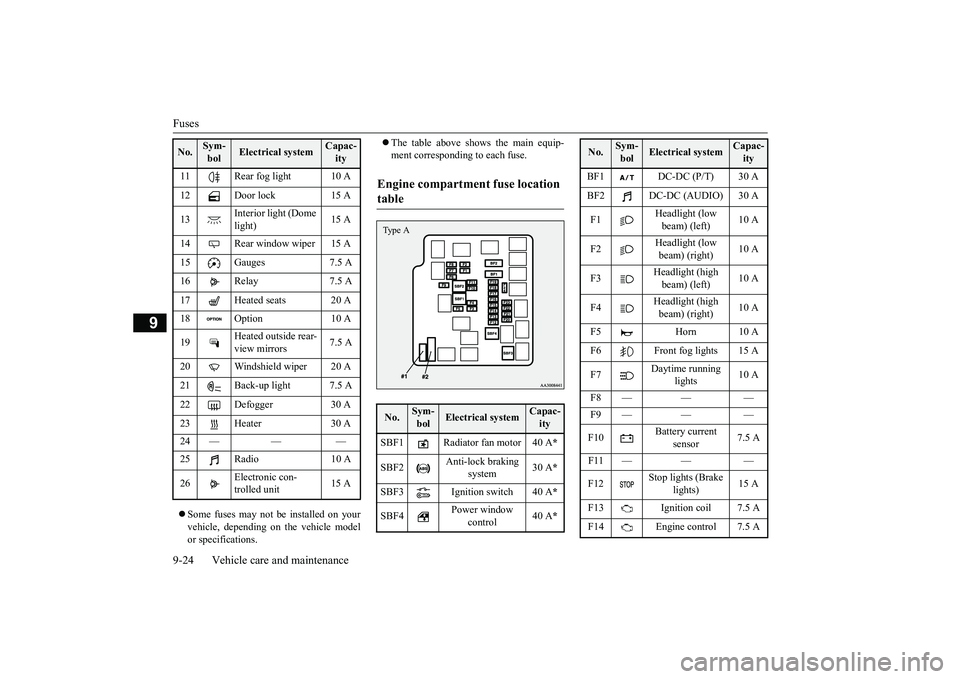
Fuses 9-24 Vehicle care and maintenance
9
Some fuses may not be installed on your vehicle, depending on the vehicle model or specifications.
The table above show
s the main equip-
ment corresponding to each fuse.
11 Rear fog light 10 A 12 Door lock 15 A 13
Interior light (Dome light)
15 A
14 Rear window wiper 15 A 15 Gauges 7.5 A16 Relay 7.5 A 17 Heated seats 20 A 18 Option 10 A 19
Heated outside rear- view mirrors
7.5 A
20 Windshield wiper 20 A 21 Back-up light 7.5 A22 Defogger 30 A 23 Heater 30 A 24 — — — 25 Radio 10 A 26
Electronic con- trolled unit
15 A
No.
Sym- bol
Electrical system
Capac-ity
Engine compartment fuse location table No.
Sym- bol
Electrical system
Capac-ity
SBF1 Radiator fan motor 40 A
*
SBF2
Anti-lock braking
system
30 A
*
SBF3 Ignition switch 40 A
*
SBF4
Power window
control
40 A
*
Type A
BF1 DC-DC (P/T) 30 A BF2 DC-DC (AUDIO) 30 A F1
Headlight (low beam) (left)
10 A
F2
Headlight (low beam) (right)
10 A
F3
Headlight (high beam) (left)
10 A
F4
Headlight (high beam) (right)
10 A
F5 Horn 10 A F6 Front fog lights 15 A F7
Daytime running
lights
10 A
F8 — — — F9 — — — F10
Battery current
sensor
7.5 A
F11 — — —F12
Stop lights (Brake
lights)
15 A
F13 Ignition coil 7.5 A F14 Engine control 7.5 ANo.
Sym- bol
Electrical system
Capac-ity
BK0249600US.book 24 ページ 2017年4月20日 木曜日 午後1時36分
Page 234 of 263

Fuses
Vehicle care and maintenance 9-25
9
* : Fusible link Some fuses may not be installed on your vehicle, depending on
the vehicle model
or specifications. The table above show
s the main equip-
ment corresponding to each fuse.
* : Fusible link Some fuses may not be installed on your vehicle, depending on
the vehicle model
or specifications. The table above shows the main equip- ment corresponding to each fuse.
The fuse block does not contain spare 7.5 A, 10 A or 15 A fuses. If one of these fuses burns out, substitute with the following fuse. 7.5 A: Outside rearview mirrors10 A: Option
15 A: Cigarette lighter When using a substitute
fuse, replace with a
fuse of the correct capa
city as soon as possi-
ble.
N00954900131
1. Before replacing a fuse, always turn off the electrical item concerned to the fuseand turn the ignition switch to the “OFF” position or put the operation mode in OFF.2. There is a fuse remover (A) in the engine compartment fuse block.
F15 Alternator 7.5 A F16
Hazard warning
flasher
10 A
F17
Automatic trans-
axle
15 A
F18 Air conditioning 10 A F19 ETV 15 AF20 Starter 7.5 A F21 CVT oil/pump 15 A F22 Fuel pump 15 A F23 Engine 20 A F24
Automatic trans-
axle
7.5 A
#1 — Spare fuse 20 A #2 — Spare fuse 30 ANo.
Sym- bol
Electrical system
Capac-ity
No.
Sym-bol
Electrical system
Capac-ity
SBF1 PTC heater 40 A
*
SBF2 PTC heater 40 A
*
SBF3 PTC heater 40 A
*
Type B
Identification of fuse Capacity
Color
7.5 A Brown 10 A Red 15 A Blue 20 A Yellow 30 A
Green (fuse type
) /Pink (fusible
link type)
40 A Green (fusi
ble link type)
Fuse replacement
BK0249600US.book 25 ページ 2017年4月20日 木曜日 午後1時36分
Page 260 of 263

Alphabetical index
12-3
12
Heater without air conditioning function
.7-4
High beam indicator
............................
5-75
High coolant temperature warning light 5-77 High-mounted stop light
Bulb capacity
.................................
9-27
Hill start assist
....................................
5-47
HomeLink® Wirele
ss Control System
..5-86
Hood lock release me
chanism and safety
catch
................................................
9-22
Hook
Convenience hook
..........................
5-94
Horn switch
........................................
5-84
I
If the vehicle breaks down
.....................
8-2
Ignition switch
....................................
5-36
Important facts to know in
case of an accident
10-4 Indicator and warning light package
.....
5-74
Indicators
...........................................
5-75
Information display
.............................
5-66
Inside emergency trunk lid release
........
5-28
Inside rearview mirror
.........................
5-33
Instrument panel light dimmer control
..5-67
Interior lights
......................................
5-91
J
Jack
Garage jack up position
.....................
9-3
Storage
............................................
8-5
Jump-starting the engine
.......................
8-2
K
Key slot
.............................................
5-18
Keyless entry system
....................
5-6
, 5-21
Keys
...................................................
5-2
L
Labeling
............................................
11-2
License plate lights
Bulb capacity
.................................
9-27
Replacement
..................................
9-32
Link System
.......................................
5-84
Loading information
.............................
6-6
Lubricants
.........................................
11-6
M
Malfunction indicator light
..................
5-76
Manual air conditioning
........................
7-7
Manual transaxle
................................
5-39
Oil
..........................................
9-9
, 11-6
Shift points
....................................
5-40
Manual window control
.......................
5-29
Modifications to and
racing of your vehicle
..
3-5 Multi-information display
...........
5-63
, 5-64
O
Octane number
.....................................
3-2
Oil
Engine oil
...............................
9-5
, 11-6
Manual transaxle oil
.................
9-9
, 11-6
Oil pressure warning light
....................
5-77
Operation mode
..................................
5-13
Operation under adverse driving conditions
..
8-13 Outside rearview mirrors
.....................
5-35
Overheating
..........................................
8-4
P
Parking
................................................
6-5
Parking brake lever stroke
...............
9-19
Parking brake
............................
5-32
, 9-19
Parking lights
Bulb capacity
.................................
9-27
Replacement
...................................
9-29
Polishing
............................................
9-35
Power brakes
......................................
5-46
Power outlet
.......................................
5-86
BK0249600US.book 3 ページ 2017年4月20日 木曜日 午後1時36分