ESP MITSUBISHI MIRAGE G4 2020 (in English) User Guide
[x] Cancel search | Manufacturer: MITSUBISHI, Model Year: 2020, Model line: MIRAGE G4, Model: MITSUBISHI MIRAGE G4 2020Pages: 253, PDF Size: 36.39 MB
Page 89 of 253
Free-hand Advanced
Security Transmitter (F.A.S
.T.-key) (if so equipped)
5-24 Features and controls
5
N00562101177
1. Before replacing the battery, remove static electricity from your body by touching ametal grounded object. 2. Remove the emergency key from the F. A . S . T- k e y.Refer to “Emergency key” on page 5-19.
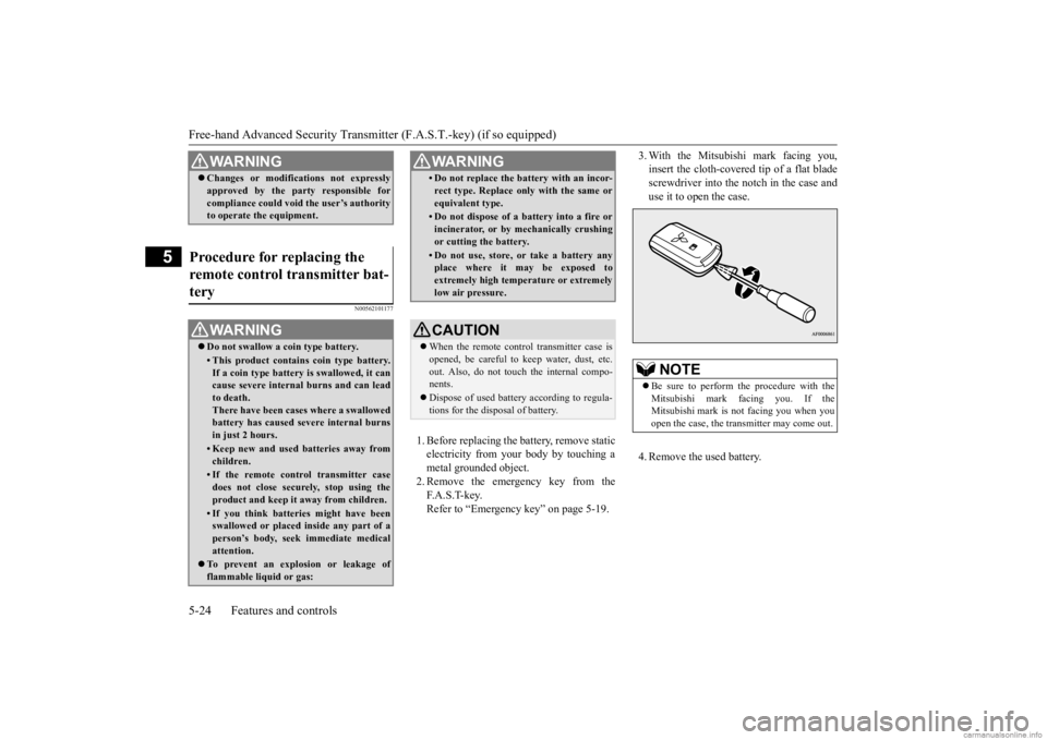
3. With the Mitsubishi mark facing you, insert the cloth-covered tip of a flat bladescrewdriver into the notch in the case and use it to open the case. 4. Remove the used battery.
WA R N I N G Changes or modifications not expressly approved by the part
y responsible for
compliance could void
the user’s authority
to operate the equipment.
Procedure for replacing the remote control transmitter bat- tery
WA R N I N G Do not swallow a coin type battery.• This product contains coin type battery. If a coin type battery is swallowed, it can cause severe internal burns and can leadto death. There have been case
s where a swallowed
battery has caused severe internal burnsin just 2 hours.• Keep new and used batteries away fromchildren.• If the remote control transmitter casedoes not close securely, stop using theproduct and keep it away from children.• If you think batter
ies might have been
swallowed or placed in
side any part of a
person’s body, seek immediate medical attention.
To prevent an explosion or leakage of flammable liquid or gas:
• Do not replace the battery with an incor-rect type. Replace only with the same orequivalent type.• Do not dispose of a battery into a fire orincinerator, or by mechanically crushingor cutting the battery.• Do not use, store, or take a battery anyplace where it may be exposed to extremely high temperature or extremely low air pressure.CAUTION When the remote control transmitter case is opened, be careful to keep water, dust, etc.out. Also, do not touch the internal compo- nents. Dispose of used battery according to regula- tions for the disposal of battery.WA R N I N G
NOTE
Be sure to perform the procedure with the Mitsubishi mark fa
cing you. If the
Mitsubishi mark is not facing you when youopen the case, the transmitter may come out.
BK0284300US.book 24 ページ 2019年5月23日 木曜日 午後12時22分
Page 90 of 253
Door locks
Features and controls 5-25
5
5. Install a new battery with the + side (A) up. 6. Close the case firmly. 7. Install the emergency key removed in step2. 8. Check the keyless entry system to see that it works.
N00509201599
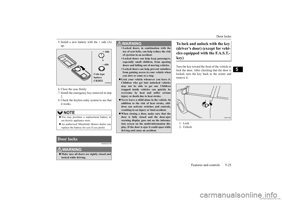
Turn the key toward the front of the vehicle to lock the door. After checking that the door is locked, turn the key back to the center andremove it.
NOTE
You may purchase a replacement battery at an electric appliance store. An authorized Mitsubish
i Motors dealer can
replace the battery for you if you prefer.
Door locks
WA R N I N G Make sure all doors are tightly closed and locked while driving.
+ side - side
Coin type battery CR2032
• Locked doors, in co
mbination with the
use of seat belts, can help reduce the riskof ejection in an accident.• Locked doors can help keep passengers,especially small children, from openingdoors and falling out of moving vehicles.• Locked doors can help prevent outsidersfrom gaining access
to your vehicle when
you slow or come to a stop.
Lock your vehicle whenever you leave it. Children who get into unlocked vehicles may not be able to get out. Childrentrapped inside vehicles can quickly be overcome by heat and suffer serious injury or death due to heat stroke. Never leave a child alone in the vehicle. In addition to the risk
of heat stroke, chil-
dren can activate switches and controls, resulting in an injury
or fatal accident.
When closing a door,
make sure that the
door is fully closed and the door-ajar warning display goes out on the informa-tion screen on the multi-information dis- play. If the door is aj
ar it could
open while
driving and caus
e an accident.
WA R N I N G
To lock and unlock with the key (driver’s door) (except for vehi-cles equipped with the F.A.S.T.- key) 1- Lock 2- Unlock
BK0284300US.book 25 ページ 2019年5月23日 木曜日 午後12時22分
Page 93 of 253
Child safety locks for rear door 5-28 Features and controls
5
N00509401315
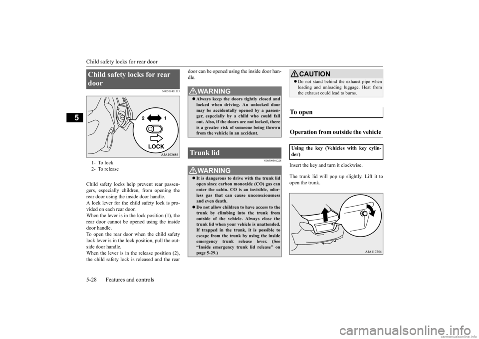
Child safety locks help prevent rear passen- gers, especially children, from opening therear door using the inside door handle. A lock lever for the child safety lock is pro- vided on each rear door.When the lever is in the lock position (1), the rear door cannot be opened using the inside door handle.To open the rear door when the child safety lock lever is in the lock position, pull the out- side door handle.When the lever is in the release position (2), the child safety lock is released and the rear
door can be opened using the inside door han- dle.
N00509501228
Insert the key and turn it clockwise. The trunk lid will pop up slightly. Lift it to open the trunk.
Child safety locks for rear door 1- To lock 2- To release
WA R N I N G Always keep the door
s tightly closed and
locked when driving. An unlocked door may be accidentally
opened by a passen-
ger, especially by
a child who could fall
out. Also, if the doors are not locked, there is a greater risk of
someone being thrown
from the vehicle in an accident.
Trunk lid
WA R N I N G It is dangerous to drive with the trunk lid open since carbon mo
noxide (CO) gas can
enter the cabin. CO is an invisible, odor- less gas that can cause unconsciousnessand even death. Do not allow children to have access to the trunk by climbing into the trunk from outside of the vehicl
e. Always close the
trunk lid when your vehicle is unattended.If trapped in the trunk, it is possible toescape from the trunk by using the inside emergency trunk re
lease lever. (See
“Inside emergency tr
unk lid release” on
page 5-29.)
CAUTION Do not stand behind the exhaust pipe when loading and unloading
luggage. Heat from
the exhaust could lead to burns.
To open Operation from outside the vehicle Using the key (Vehicles with key cylin- der)
BK0284300US.book 28 ページ 2019年5月23日 木曜日 午後12時22分
Page 95 of 253
Power window control 5-30 Features and controls
5
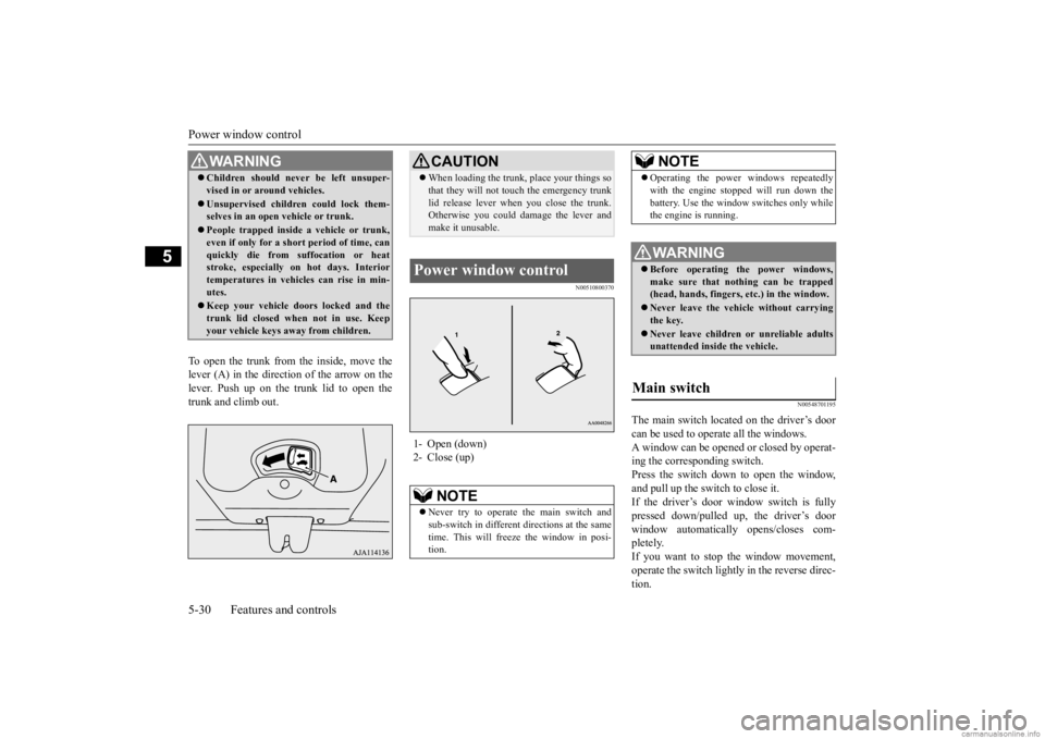
To open the trunk from the inside, move the lever (A) in the direction of the arrow on thelever. Push up on the trunk lid to open the trunk and climb out.
N00510800370
N00548701195
The main switch located on the driver’s door can be used to operate all the windows. A window can be opened or closed by operat- ing the corresponding switch.Press the switch down to open the window, and pull up the switch to close it. If the driver’s door window switch is fullypressed down/pulled up, the driver’s door window automatically opens/closes com- pletely.If you want to stop the window movement, operate the switch lightly in the reverse direc- tion.
WA R N I N G Children should never be left unsuper- vised in or ar
ound vehicles.
Unsupervised children could lock them- selves in an open vehicle or trunk. People trapped inside a vehicle or trunk, even if only for a short period of time, can quickly die from su
ffocation or heat
stroke, especially on
hot days. Interior
temperatures in vehicles can rise in min- utes. Keep your vehicle d
oors locked and the
trunk lid closed when not in use. Keepyour vehicle keys away from children.
CAUTION When loading the trunk, place your things so that they will not touch the emergency trunklid release lever when you close the trunk.Otherwise you could da
mage the lever and
make it unusable.
Power window control 1- Open (down) 2- Close (up)
NOTE
Never try to operate the main switch and sub-switch in different directions at the sametime. This will free
ze the window in posi-
tion.
Operating the power windows repeatedly with the engine stopped will run down thebattery. Use the window
switches only while
the engine is running.WA R N I N G Before operating the power windows, make sure that nothing can be trapped (head, hands, fingers, etc.) in the window. Never leave the vehi
cle without carrying
the key. Never leave children
or unreliable adults
unattended inside the vehicle.
Main switch
NOTE
BK0284300US.book 30 ページ 2019年5月23日 木曜日 午後12時22分
Page 97 of 253
Power window control 5-32 Features and controls
5
N00528801220
If a hand or head is trapped, for safety the door window is automati
cally lowered a little.
After the door window is lowered, clear the obstruction, then pull up the switch again toclose the door window.
N00551400043
Wind buffeting can be de
scribed as the per-
ception of pressure on the ears or a booming or rumbling sound. Your
vehicle may exhibit
wind buffeting when driving with one or bothrear door windows down or partially opened. This is a normal occurrence that can be mini- mized. If the buffeting
occurs with the rear
door windows open, open the front door win- dows as well as the rear door windows to minimize the condition.
WA R N I N G Before driving with a child in the vehicle, be sure to lock the window switch to makeit inoperative. Children tampering withthe switch could easily trap their hands or heads in the window.
Safety mechanism (Driver’s door window)
WA R N I N G If the battery terminals are disconnected or the fuse for electric window is replaced, the safety mechanism will be cancelled. If a hand or head got
trapped, a serious
injury could result.CAUTION The safety mechanism is deactivated just before the door window closes. This allows the door window to close completely. There- fore be especially careful that fingers are nottrapped in the door window opening.
The safety mechanism is deactivated while the switch is pulled up.
Therefore be espe-
cially careful that fi
ngers are not trapped in
the door window opening. Do not deliberately tr
ap your hands or head
in order to activate the safety mechanism. Your hand or head coul
d be trapped and per-
sonal injury could result.NOTE
The safety mechanism can be activated if the driving conditions or
other circumstances
cause the door window to be subjected to a physical shock similar to that caused by trapped hand or head. If the safety mechanism is activated 5 or more times in a row, the safety mechanismwill be cancelled a
nd the door window will
not close correctly. In such a case, the following procedureshould be implemented to rectify this situa- tion. If the window is open,
repeatedly raise the
driver’s door window sw
itch until that win-
dow has been fully cl
osed. Following this,
release the switch, raise the switch once again and hold it in this condition for atleast1 second, then release it. You should now be able to operate
in the normal fashion.
CAUTION
If the battery terminals are disconnected or the fuse for electric
window is replaced, the
safety mechanism will
be cancelled and the
door window will not automatically open/close completely. If the window is open,
repeatedly raise the
driver’s door window switch until the win- dow has been fully cl
osed. Following this,
release the switch, raise the switch onceagain and hold it in this
condition for at least
1 second, then release it. You should now be able to operate the driver’s door window inthe normal fashion.
What to do if you hear wind buffeting when driving
NOTE
BK0284300US.book 32 ページ 2019年5月23日 木曜日 午後12時22分
Page 110 of 253
Continuously variable transmission (CVT) (if so equipped)
Features and controls 5-45
5
N00549500018 N00574601049
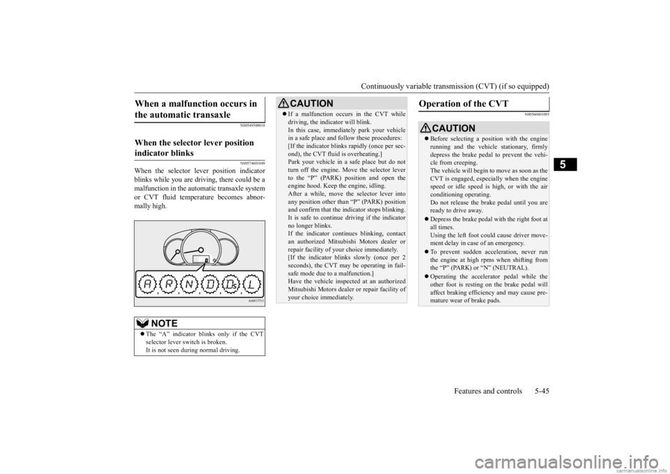
When the selector le
ver position indicator
blinks while you are driv
ing, there could be a
malfunction in the automatic transaxle system or CVT fluid temperature becomes abnor- mally high.
N00560801095
When a malfunction occurs in the automatic transaxle
When the selector lever position indicator blinks
NOTE
The “A” indicator blinks only if the CVT selector lever sw
itch is broken.
It is not seen during normal driving.
CAUTION If a malfunction occurs in the CVT while driving, the indicator will blink.In this case, immediat
ely park your vehicle
in a safe place and fo
llow these procedures:
[If the indicator blinks
rapidly (once per sec-
ond), the CVT fluid is overheating.]Park your vehicle in a safe place but do not turn off the engine. M
ove the selector lever
to the “P” (PARK) position and open theengine hood. Keep th
e engine, idling.
After a while, move the selector lever into any position other than “P” (PARK) positionand confirm that the i
ndicator stops blinking.
It is safe to continue driving if the indicator no longer blinks.If the indicator contin
ues blinking, contact
an authorized Mitsubishi Motors dealer or repair facility of your
choice i
mmediately.
[If the indicator blinks slowly (once per 2 seconds), the CVT may
be operating in fail-
safe mode due to a malfunction.]Have the vehicle inspected at an authorized Mitsubishi Motors dealer
or repair facility of
your choice immediately.
Operation of the CVT
CAUTION Before selecting a pos
ition with the engine
running and the vehicl
e stationary, firmly
depress the brake pedal to prevent the vehi- cle from creeping. The vehicle will begin to move as soon as theCVT is engaged, especi
ally when the engine
speed or idle speed is
high, or with the air
conditioning operating.Do not release the brak
e pedal until you are
ready to drive away. Depress the brake pedal
with the right foot at
all times. Using the left foot could cause driver move-ment delay in case of an emergency. To prevent sudden acce
leration, never run
the engine at high rpms when shifting from the “P” (PARK) or “N” (NEUTRAL). Operating the accelerator pedal while the other foot is resting
on the brake pedal will
affect braking efficiency and may cause pre-mature wear of brake pads.
BK0284300US.book 45 ページ 2019年5月23日 木曜日 午後12時22分
Page 111 of 253
Service brake 5-46 Features and controls
5
To gain extra acceleration in “D” (DRIVE) position (when passing an
other vehicle) push
the accelerator to the floor. The CVT will automatically downshift.
For short waiting periods, such as at traffic lights, the vehicle can be
left in selector lever
position and held stationary with the servicebrake. For longer waiting periods with the engine running, place th
e selector lever in the “N”
(NEUTRAL) position and apply the parking brake, while holding the vehicle stationary with the service brake. Prior to moving off after having stopped the vehicle, make sure that the selector lever is in“D” (DRIVE) position. To park the vehicle, fi
rst bring it to a com-
plete stop, fully engage the parking brake,
and then move the selector lever to the “P” (PARK) position. If the CVT does not shift while driving, or your vehicle does not pick up enough speed when starting on an uphill slope, it may bethat there is something unusual happening in the transmission. Have your vehicle checked at an authorized Mitsubishi Motors dealer or a repair facility of your choice immediately.
N00517501328
Overuse of the brake can cause weakening,resulting in poor brake response and prema- ture wear of the brake pads.When driving down a long or steep hill, use engine braking by moving
the selector lever
to “Ds” (DOWNSHIFT & SPORTY DRIV-ING) or “L” (LOW) position.
Use the selector lever in the correct shift position in accordance
with driving condi-
tions.Never coast downhill backward in the driv- ing shift position “D” (DRIVE), “Ds” (DOWNSHIFT & SPORTY DRIVING), “L”(LOW) or coast forward in the “R” (REVERSE) position. Engine stopping and in
creased brake pedal
and steering effort could
lead to an accident.
Do not rev the engine
with the brake pedal
pressed when the vehi
cle is stationary.
This can damage the CVT. Also, when you depress
the accelera
tor pedal
while holding down the brake pedal with the selector lever in the “D” (DRIVE) position, the engine revolutions
may not rise as high
as when performing the same operation with the selector lever in the “N” (NEUTRAL) position.
Passing acceleration
CAUTION
Wa i t in g
CAUTION To avoid transmission overheating, never try to keep your vehicle stationary on a hill by using the accelerator
pedal. Always apply
the parking brake and/or service brake. Do not rev the engine unnecessarily while the vehicle is stationary. Unexpected acceler-ation may occur if the se
lector lever is in a
position other than “P” (PARK) or “N” (NEUTRAL).
Parking
When the CVT makes no speed change
Service brake Brake pedal
BK0284300US.book 46 ページ 2019年5月23日 木曜日 午後12時22分
Page 115 of 253
Anti-lock braking system 5-50 Features and controls
5
When the anti-lock braking system is in use, you may feel the brake pedal vibrat-ing and hear a unique
sound. It may also
feel as if the pedal
resists being pressed.
In this situation, simply hold the brakepedal down firmly. Do not pump the brake, which will result in reduced braking performance.
N00531600674
If there is a malfunction in the system, the anti-lock braking system warning light will come on.Under normal conditions, the ABS warning light comes on when the ignition switch is turned to the “ON” position or the operationmode is put in ON and goes off a few seconds later.
N00531700604
Avoid hard braking and high-speed driv- ing. Stop the vehicle in a safe place.Test the system by restarting the engine and driving at a speed of about 12 mph (20 km/h) or higher.If the warning light then remains off dur- ing driving, there is no abnormal condi- tion.However, if the warning light does not disappear, or if they come on again when the vehicle is driven, have the vehiclechecked by an authorized MITSUBISHI MOTORS dealer or re
pair facility of your
choice as soon
as possible.
CAUTIONThe anti-lock braking system cannot prevent accidents. It is your responsibility to take safety precautions a
nd to drive carefully.
To prevent failure of the anti-lock braking system, be sure all 4 wheels and tires are the same size and the same type.NOTE
You may feel the ope
rating sound or vibra-
tion from under the body when driving immediately after starti
ng the engine. This is
a normal result the anti-lock braking systemmakes when performing a self-check. It does not indicate a problem. The anti-lock braking system can be used after the vehicle has
reached a speed over
approximately 6 mph (10 km/h). It stops working when the vehicle slows below 3mph (5 km/h).
Anti-lock braking system warn- ing light
CAUTION Any of the following i
ndicates that the anti-
lock braking system is not functioning andonly the standard brake system is working. (The standard brake system is functioning normally.) If this happens, take your vehicleto an authorized Mitsubishi Motors dealer or a repair facility
of your choice.
• When the ignition switch is turned to the “ON” position or the
operation mode is put
in ON, the warning light does not come onor it remains on and does not go off.• The warning light comes on while driving
If the warning light illuminate while driving If only the anti-lock braking sys- tem warning light illuminate
CAUTION
BK0284300US.book 50 ページ 2019年5月23日 木曜日 午後12時22分
Page 117 of 253
Active stability control (ASC) 5-52 Features and controls
5
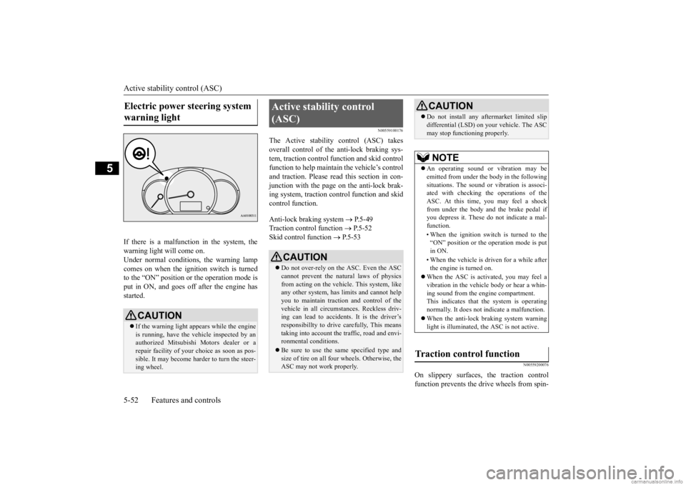
If there is a malfunction in the system, the warning light will come on. Under normal conditions, the warning lamp comes on when the ignition switch is turnedto the “ON” position or the operation mode is put in ON, and goes off after the engine has started.
N00559100176
The Active stability control (ASC) takes overall control of the anti-lock braking sys- tem, traction control function and skid controlfunction to help maintain
the vehicle’s control
and traction. Please read
this section in con-
junction with the page on the anti-lock brak-ing system, traction c
ontrol function and skid
control function. Anti-lock braking system
P.5-49
Traction control function
P.5-52
Skid control function
P.5-53
N00559200076
On slippery surfaces, the traction control function prevents the drive wheels from spin-
Electric power steering system warning light
CAUTION If the warning light appears while the engine is running, have the vehicle inspected by an authorized Mitsubishi Motors dealer or arepair facility of your
choice as soon as pos-
sible. It may become ha
rder to turn the steer-
ing wheel.
Active stability control (ASC)
CAUTION Do not over-rely on the ASC. Even the ASC cannot prevent the natural laws of physicsfrom acting on the vehicle. This system, like any other system, has
limits and cannot help
you to maintain traction and control of thevehicle in all circumstances. Reckless driv- ing can lead to accident
s. It is the driver’s
responsibillty to drive carefully, This meanstaking into account the traffic, road and envi- ronmental conditions. Be sure to use the same specified type and size of tire on all four
wheels. Otherwise, the
ASC may not work properly.
Do not install any aftermarket limited slip differential (LSD) on
your vehicle. The ASC
may stop functioning properly.NOTE
An operating sound or vibration may be emitted from under the body in the followingsituations. The sound or vibration is associ- ated with checking th
e operations of the
ASC. At this time,
you may feel a shock
from under the body and the brake pedal if you depress it. These do
not indicate a mal-
function. • When the ignition switch is turned to the “ON” position or the
operation mode is put
in ON. • When the vehicle is driven for a while after the engine is turned on.
When the ASC is acti
vated, you may feel a
vibration in the vehicl
e body or hear a whin-
ing sound from the engine compartment. This indicates that th
e system is operating
normally. It does not i
ndicate a malfunction.
When the anti-lock braking system warning light is illuminated, the ASC is not active.
Traction control function
CAUTION
BK0284300US.book 52 ページ 2019年5月23日 木曜日 午後12時22分
Page 125 of 253

Tire pressure monitoring system (TPMS) 5-60 Features and controls
5
Each tire, including the spare, should be checked monthly when cold and inflated tothe inflation pressure recommended by the vehicle manufac
turer on the vehicle placard
or tire inflation pressu
re label. (If your vehi-
cle has tires of a different size than the size indicated on the vehicle
placard or tire infla-
tion pressure label, yo
u should determine the
proper tire inflation pr
essure for those tires.)
As an added safety feature, your vehicle has been equipped with a tire pressure monitoring system (TPMS) that illuminates a low tire pressure telltale when
one or more of your
tires is significant
ly under-inflated.
Accordingly, when the low tire pressure tell- tale illuminates, you should stop and checkyour tires as soon as possible, and inflate them to the proper pressure. Driving on a sig- nificantly under-inflated
tire causes the tire to
overheat and can lead
to tire failure.
Under-inflation also reduces fuel efficiency and tire tread life, and may affect the vehi-cle’s handling and stopping ability. Please note that the TPMS is not a substitute for proper tire maintenance, and it is the driver’sresponsibility to mainta
in correct tire pres-
sure, even if under-inf
lation has not
reached
the level to trigger illumination of the TPMSlow tire pressure telltale. Your vehicle has also been equipped with a TPMS malfunction indicator to indicate when
the system is not operating properly. The TPMS malfunction indicator is combinedwith the low tire pressure telltale. When the system detects a malfunction, the telltale will flash for approximately one min-ute and then remain c
ontinuously illuminated.
This sequence will c
ontinue upon subsequent
vehicle start-ups as long as the malfunctionexists. When the malfunction indicator is illumi- nated, the system may not
be able to detect or
signal low tire pr
essure as intended.
TPMS malfunctions may
occur for a variety
of reasons, including the installation of replacement or alternate tires or wheels on the vehicle that prevent the TPMS from function-ing properly. Always
check the TPMS mal-
function telltale after replacing one or more tires or wheels on your vehicle to ensure thatthe replacement or alternate tires and wheels allow the TPMS to continue to function prop- erly.
N00532801612
1. If the tire pressure monitoring systemwarning light illum
inates, avoid hard
braking, sharp steering maneuvers and high speeds. You should stop and adjust the tires to the proper inflation pressure assoon as possible. Adjust the spare tire at the same time. Refer to “Tires” on page 9-12.
If the warning light illuminates while driving
NOTE
When inspecting or adjusting the tire pres- sure, do not apply excessive force to the valve stem to
avoid breakage.
After inspecting or adjusting the tire pres- sure, always reinstall the valve cap on thevalve stem. Without the valve cap, di
rt or moisture could
get into the valve, resulting in damage to thetire inflation pressure sensor. Do not use metal valve caps, which may cause a metal reaction,
resulting in corrosion
and damage of the tire
inflation pressure sen-
sors. Once adjustments have
been made, the warn-
ing light will go off after a few minutes ofdriving.
BK0284300US.book 60 ページ 2019年5月23日 木曜日 午後12時22分